1. Baud rate is unknown, again next time, the first bath
2. shift operation
3.P0 and P0 ^ 0
/*******************************************************************************
延时函数
i=1,延时10微秒
i=50000,延时450ms
*******************************************************************************/
void delay(u16 i)
{
	while(i--);
}
Why is the time delay of 450 milliseconds 50,000? 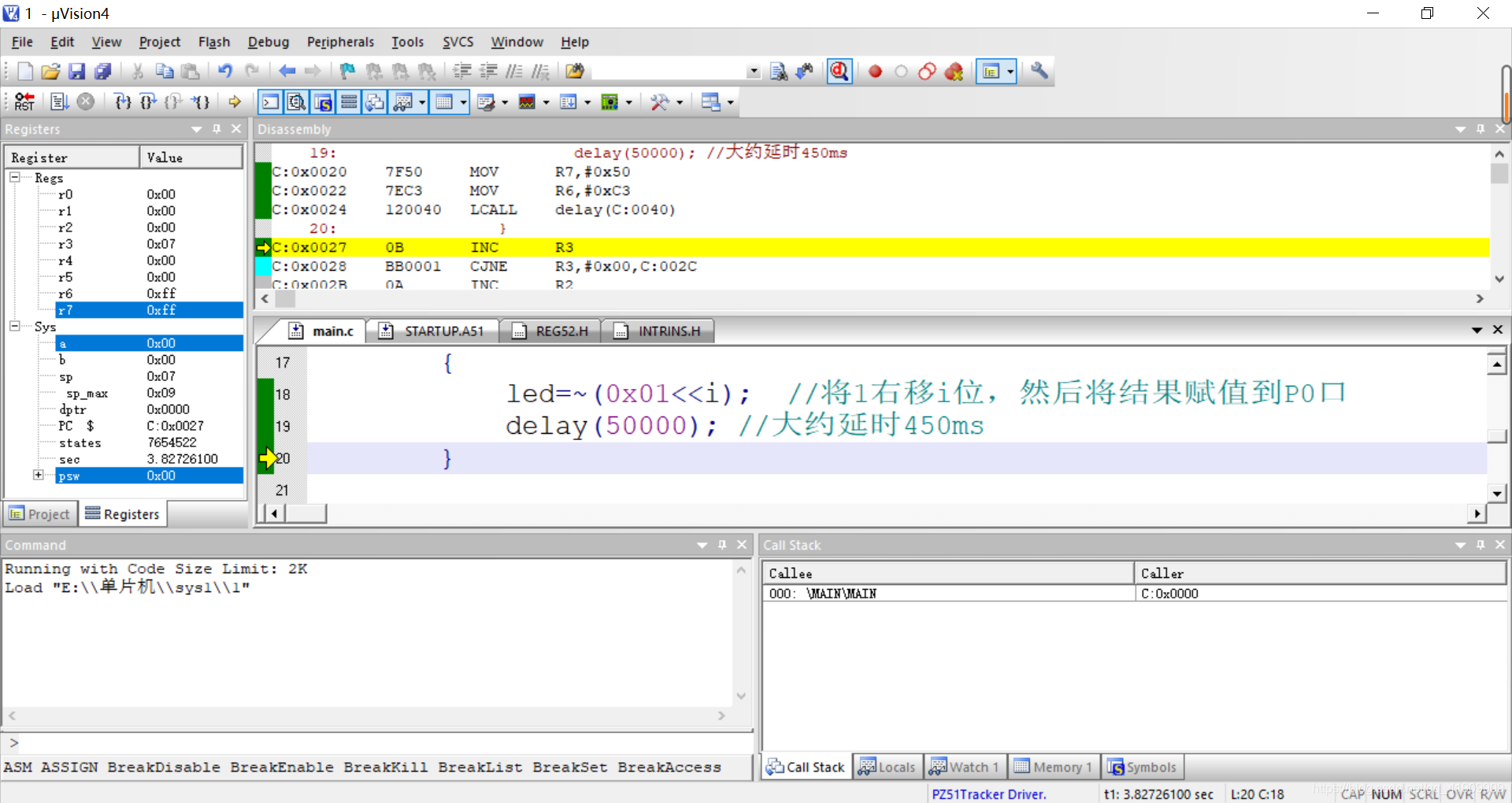


Single-step debugging through, we can see the gap between the two is almost 450 milliseconds.
Delay time is how much, only by this statement can not be determined, related to many factors, such as the size of the crystal, the instruction cycle time, etc., for example, is also a 12M crystal, 8051 is the instruction cycle is 1us, and STC89C51 is 0.5us ; STC12C5A60S2 is 1 / 12us.
"12MHz crystal oscillator with 51 computers 11.0592MHz application difference."
T1 is set in Mode 2, 8-bit count register, automatically reload the initial count value,
N is the initial count value is written when initializing THI and TH2,
the SMOD set to 0 (no multiplication) baud rate = Fosc / [(32x12x (256-N)]
If the crystal is 12MHz, N = 243,
the baud rate = (12x10 ^ 6) / [ 32x12x (256-243)] = 2403.846b / s
erroneous 3.846b / s of
If the crystal is 11.0592MHz, the initial count value N = 244,
the baud rate generated = 11059200 / [32x12x (256-244) = 2400b / s, accurate.
[Summary]
If the device for serial communication, data reliability is improved, the crystal should be used 11.0592MHz;
If the device is used for other purposes, the choice of 12MHz crystal.
The argument is typical bench, looks very reasonable.
Think, 11.0592, 11.0592 some work to do? Measure had not?
12M, 12M must work to do, really not up to 9600 baud rate?
If 9606 becomes how will it?
In fact, most of the crystal are not allowed on the market. 2 cents deviation of a crystal oscillator is often less than 0.1%. Discuss on this basis difference between the two is not much significance.
However, good crystal, indeed as said bench.
For serial communication, baud rate is allowed to have differences, so you can be in the vicinity of 9600. In this sense, 11.0592 and 12.00 can bring in. (Of course, parameters or different, is not the direct substitution).
If the two machines with 12M, or two machines with 11.0592, will be 12, with a 11.0952 better than with one. But nor is it can not be used.
Landlord this question, is due to the serial communication is not deep understanding of, understand thoroughly, it does not matter the 12 or 11.0592.
Only some special occasions to appear rather than using only 11.0592 12.00. Mainly in the hardware division, or in the case where there is a phase requirements, as well as high-speed communication.
Standard single-chip oscillator 51 is 1.2M-12M, typically because a machine cycle is 12 clock cycles, so that when the first 12M, a machine cycle is 1US, easy to calculate, but the relative velocity is the highest (now of course, have a higher frequency SCM).
11.0592M because during communication, 12M frequency standard serial communication baud rate is not easily achieved, such as 9600,4800, while 11.0592M can be calculated exactly, and therefore there is a communication interface of the microcontroller, general election 11.0592 M

You look at your crystal microcontroller how much I was 11.0592MHZ, if you do 1us delay, you can look at me,
/ ****************** *******************************
function: // 15us delay function
Description: // achieve an integer multiple of the delay of 15us
the INPUT: // unsigned int i
******************************************* ***** /
void Delay_15us (unsigned int I) // 15 I + 15us delay time
{
for (I; I> 0; I-)
{
NOP ();
NOP ();
NOP ();
NOP ();
}
nop ();
nop ();
}
if 1us if you do, then you can write directly _nop_ (); this is a dummy instruction, the system does nothing, probably delay 1us, so if you wanted to write, then it to include the header file #include <intrins.h>
/**************************************************************************************
实验现象:下载程序后"LED&交通灯模块"的D1指示灯闪烁
接线说明: 单片机-->LED&交通灯模块(具体接线图可见开发攻略对应实验的“实验现象”章节)
		   P00-->D1
注意事项:
***************************************************************************************/

#include "reg52.h"			 //此文件中定义了单片机的一些特殊功能寄存器
typedef unsigned int u16;	  //对数据类型进行声明定义
typedef unsigned char u8;


sbit led=P0^0;		 //将单片机的P0.0端口定义为led

/*******************************************************************************
* 函 数 名         : delay
* 函数功能		   : 延时函数,i=1时,大约延时10us
*******************************************************************************/
void delay(u16 i)
{
	while(i--);
}

/*******************************************************************************
* 函 数 名       : main
* 函数功能		 : 主函数
* 输    入       : 无
* 输    出    	 : 无
*******************************************************************************/
void main()
{
	while(1)
	{
		led=0;
		delay(50000); //大约延时450ms
		led=1;
		delay(50000); //大约延时450ms
	}
}
/**************************************************************************************
实验现象:下载程序后"LED&交通灯模块"的D1-D8呈现流水灯效果
接线说明: 单片机-->LED&交通灯模块(具体接线图可见开发攻略对应实验的“实验现象”章节)
		   P00-->D1
		   P01-->D2
		   ...
		   P07-->D8
注意事项:
***************************************************************************************/

#include "reg52.h"			 //此文件中定义了单片机的一些特殊功能寄存器
#include<intrins.h>		//因为要用到左右移函数,所以加入这个头文件

typedef unsigned int u16;	  //对数据类型进行声明定义
typedef unsigned char u8;

#define led P0	   //将P0口定义为led 后面就可以使用led代替P0口

/*******************************************************************************
* 函 数 名         : delay
* 函数功能		   : 延时函数,i=1时,大约延时10us
*******************************************************************************/
void delay(u16 i)
{
	while(i--);
}

/*******************************************************************************
* 函 数 名       : main
* 函数功能		 : 主函数
* 输    入       : 无
* 输    出    	 : 无
*******************************************************************************/
void main()
{
	u8 i;
	led=~0x01;//改为0xfe,前面保持全亮
	delay(50000); //大约延时450ms
	while(1)
	{
		for(i=0;i<8;i++)
		{
			P0=~(0x01<<i);	 //将1右移i位,然后将结果赋值到P0口
			delay(50000); //大约延时450ms
		}


/*		for(i=0;i<7;i++)	 //将led左移一位
		{
			led=_crol_(led,1);
			delay(50000); //大约延时450ms
		}
		for(i=0;i<7;i++)	//将led右移一位
		{
			led=_cror_(led,1);
			delay(50000); //大约延时450ms
		}
*/
	}
}
0x01 0xFE is negated, that is, 1111 1110, resulting in a low level led lights.
If set to 0xEF, can cause the front of the lamp immortal, all lit up slowly. << it is because shift operation, moving to the left, is 111,111,100, so the two will light. Under normal circumstances is 11,111,101.
Shift operation to be verified, doubt.

Why led rather than equal to P0 P0 ^ 0? ? ? ?
Bus operation method
MCU can not sbit led light water experiment Why only use #define led P0 = P0
sbit led = P2, the wording is wrong, although not a compile-time error, but the compiler Shique program execution is wrong. sbit is to define a pin, note that only defines a pin, and P2 is a parallel port, has eight pins, not sbit defined, can be defined in sfr. #define pin is not defined, nor is it defined parallel port, just a macro substitution is a program led into P2 and then compile. So, sbit and #define is simply not the same thing, let alone what replaced. There is no relationship between the two.
Microcontroller 51 controls all but the latch of the default port io are high, i.e. the latch end LE is high, the output as the input changes.
