Project Introduction
ML-L3 is a Nikon camera models wireless infrared remote control, may control the release of the shutter by way of infrared, door support B shooting. The official price is about 100RMB, about copycat version is priced at 10RMB. Although the basic remote control function can be realized, but the function is relatively simple, such as a timer shooting can not be achieved, i.e., to delay the video imaging material produced. This article describes how to control the infrared transmitter via Arduino, MCU or FPGA, instructions which generate a shutter function wireless remote shutter.
ML-L3 remote dismantling
In order to achieve the ML-L3 remote control function, we must first understand the principle of wireless remote control. Of course the best way is to disassemble a ML-L3, and then look at the internal circuit, and then measure the infrared code. However, such a hand and no remote control, users abroad have been disassembled and the measured waveform of the infrared code, as shown below.
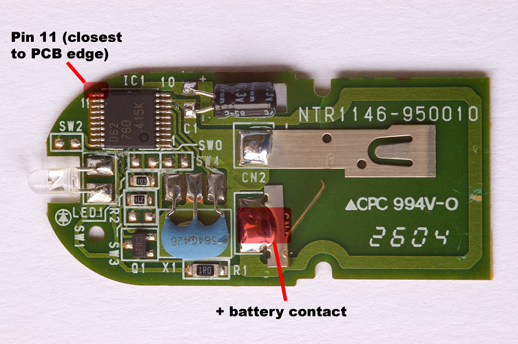
Official PCB board remote control:
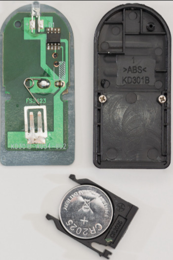
PCB board remote cottage:
From the point of view of PCB, material really is the official number is greater, by measuring the infrared emission pin when the button is pressed, infrared emission head emits a series of pulse signals, as shown below:
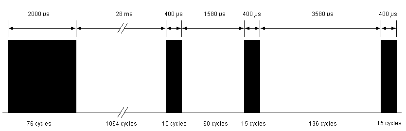
Wherein the black part is a 38KHz square wave PWM, blank portion is low, it means that a waveform of the above shutter instruction.
There are two main infrared remote control protocol: NEC and Philips RC-5 agreement protocol, NEC modulated using PWM, RC-5 modulated using PPM. Wherein the NEC is the most used protocol, 38KHz carrier, typically by the boot code address code + Address + Data + + inverted data inverted configuration. Wherein the logic 0 and logic 1 encoded as follows:

Based achieve Arduino
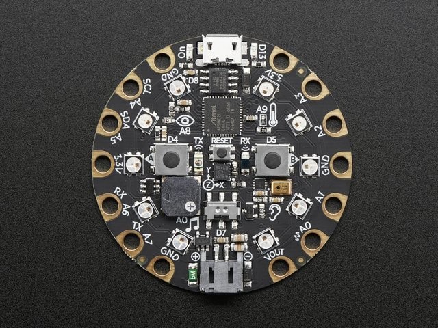
Well, knowing the infrared wave shutter instruction, we just write a bunch of functions to achieve this pulse signal on it. Arduino development board, I have plenty on hand Circuit Playground Express this development board, board one pair of infrared transmitting and receiving head, and two keys for our function is already sufficient. Before using the Cortex-M0 need to install the library.
Very simple procedure, when the key is pressed, a shutter instruction issue:
#include <Adafruit_CircuitPlayground.h>

#define IR_Pin      25
#define Led_Pin     13
#define ButtonA_Pin  4
#define ButtonB_Pin  5

#define LED_ON      digitalWrite(Led_Pin, LOW)
#define LED_OFF     digitalWrite(Led_Pin, HIGH)
#define LED_SET(x)  digitalWrite(Led_Pin, x)

#define IR_ON     digitalWrite(IR_Pin, HIGH)
#define IR_OFF    digitalWrite(IR_Pin, LOW)

#define GET_BUTTONA()  digitalRead(ButtonA_Pin)
#define GET_BUTTONB()  digitalRead(ButtonB_Pin)

int sts = 0;

void setup()
{
  pinMode(IR_Pin, OUTPUT);
  pinMode(Led_Pin, OUTPUT);
  pinMode(ButtonA_Pin, INPUT_PULLDOWN);
  pinMode(ButtonB_Pin, INPUT_PULLDOWN);

  Serial.begin(9600);
}

//Nikon ML-L3 红外遥控器快门编码:38KHz=26us
void loop()
{
  if (GET_BUTTONA())
  {
    delay(10);
    if (GET_BUTTONA())
    {
      sts = !sts;
      LED_SET(sts);
      Serial.println("Right button pressed!");
      OneShot();
    }
  }
  while (GET_BUTTONA());  //等待松开
}

void OneShot()
{
  int i = 0;
  for (i = 76; i > 0; i--)  //2100ms
  {
    IR_ON;      //13.5
    delayMicroseconds(12);
    IR_OFF;     //13.7
    delayMicroseconds(12);
  }
  IR_OFF;
  delay(28);  //2803us
  for (i = 15; i > 0; i--) //393us
  {
    IR_ON;
    delayMicroseconds(12);
    IR_OFF;
    delayMicroseconds(12);
  }
  IR_OFF;
  delayMicroseconds(1580);    //1611us

  for (i = 15; i > 0; i--)
  {
    IR_ON;
    delayMicroseconds(12);
    IR_OFF;
    delayMicroseconds(12);
  }
  delayMicroseconds(3580);
  for (i = 15; i > 0; i--)
  {
    IR_ON;
    delayMicroseconds(12);
    IR_OFF;
    delayMicroseconds(12);
  }
  IR_OFF;
}
Based achieve STM32
Implemented on STM32F103 is very simple, the main use of the GPIO control and accurate delay function. IR control pin and key pins may be adjusted as desired.
//根据Nikon ML-L3红外遥控器编码协议,产生快门指令
void OneShot(void)
{
    int i = 0;
    for(i = 76; i > 0; i--)   //2100ms
    {
        IR_ON;      //13.5
        delay_us(12);
        IR_OFF;     //13.7
        delay_us(12);
    }
    IR_OFF;
    delay_ms(28);  //2803us
    for(i = 15; i > 0; i--)  //393us
    {
        IR_ON;
        delay_us(12);
        IR_OFF;
        delay_us(12);
    }
    IR_OFF;
    delay_us(1580);    //1611us

    for(i = 15; i > 0; i--)
    {
        IR_ON;
        delay_us(12);
        IR_OFF;
        delay_us(12);
    }
    delay_us(3580);
    for(i = 15; i > 0; i--)
    {
        IR_ON;
        delay_us(12);
        IR_OFF;
        delay_us(12);
    }
    IR_OFF;
}
基于FPGA的实现
对于FPGA来说,这种波形的产生,时间可以控制的更精确,这取决于FPGA的时钟,时钟越高精度越高,而且可控性更强一些,就是实现起来稍微麻烦一些。
Verilog文件
module ml_l3_pulse_gen(

input clk_50M,  //20ns
input rst_n,
input trig,     //negedge trig

output pulse
);

parameter T1_2000US  = 100000;
parameter T2_28000US = 1400000;
parameter T3_400US   = 20000;
parameter T4_1580US  = 79000;
parameter T5_400US   = T3_400US;
parameter T6_3580US  = 179000;
parameter T7_400US   = T3_400US;

parameter T1_STS = 1;
parameter T2_STS = 2;
parameter T3_STS = 3;
parameter T4_STS = 4;
parameter T5_STS = 5;
parameter T6_STS = 6;
parameter T7_STS = 7;
parameter T8_STS = 8;
parameter T0_STS = 0;
parameter TIME_38KHZ = 658;

reg [7:0] cur_sts;
reg [31:0] cnt_38khz;
reg [31:0] cnt;
reg [31:0] cnt_max;

reg en;
reg pwm_38k;
reg trig_reg;

assign pulse = (en) ? pwm_38k : 0;

always @ (posedge clk_50M)
begin
    trig_reg <= trig;
end

always @ (posedge clk_50M)
begin
    if(!rst_n)
        cnt_max <= 0;
    else
    begin
        case (cur_sts)
            T0_STS : cnt_max <= 0;
            T1_STS : cnt_max <= T1_2000US;
            T2_STS : cnt_max <= T2_28000US;
            T3_STS : cnt_max <= T3_400US;
            T4_STS : cnt_max <= T4_1580US;
            T5_STS : cnt_max <= T5_400US;
            T6_STS : cnt_max <= T6_3580US;
            T7_STS : cnt_max <= T7_400US;
            default : cnt_max <= 0;
        endcase
    end
end

always @ (posedge clk_50M)
begin
    if(!rst_n)
        en <= 0;
    else
    begin
        case (cur_sts)
            1,3,5,7 : en <= 1;
            2,4,6,0 : en <= 0;
            default : en <= 0;
        endcase
    end
end

always @ (posedge clk_50M)
begin
    if(!rst_n)
        cnt <= 0;
    else
    begin
        if(cur_sts != T0_STS && cnt < cnt_max)
            cnt <= cnt + 1;
        else
            cnt <= 0;
    end
end

always @ (posedge clk_50M)
begin
    if(!rst_n)
        cur_sts <= T0_STS;
    else
    begin
        case (cur_sts)
            T0_STS:
                if(trig_reg & !trig)
                    cur_sts <= T1_STS;
            T1_STS:
                if(cnt == T1_2000US)
                    cur_sts <= T2_STS;
            T2_STS:
                if(cnt == T2_28000US)
                    cur_sts <= T3_STS;
            T3_STS:
                if(cnt == T3_400US)
                    cur_sts <= T4_STS;
            T4_STS:
                if(cnt == T4_1580US)
                    cur_sts <= T5_STS;
            T5_STS:
                if(cnt == T5_400US)
                    cur_sts <= T6_STS;
            T6_STS:
                if(cnt == T6_3580US)
                    cur_sts <= T7_STS;
            T7_STS:
                if(cnt == T7_400US)
                    cur_sts <= T0_STS;
            default :
                cur_sts <= T0_STS;
        endcase
    end
end

/* 38KHz counter */
always @ (posedge clk_50M)
begin
    if(!rst_n)
        cnt_38khz <= 0;
    else
    begin
        if(en && cnt_38khz < TIME_38KHZ)
            cnt_38khz <= cnt_38khz + 1;
        else
            cnt_38khz <= 0;
    end
end

/* generate 38KHz pwm */
always @ (posedge clk_50M)
begin
    if(!rst_n)
        pwm_38k <= 0;
    else if(cnt_38khz == TIME_38KHZ)
        pwm_38k <= ~pwm_38k;
end

endmodule
仿真test bench 文件
`timescale 1ns/100ps

module ml_l3_pulse_gen_tb;

parameter SYSCLK_PERIOD = 20;// 50MHZ

reg SYSCLK;
reg NSYSRESET;
reg trig;

wire pulse;

initial
begin
    SYSCLK = 1'b0;
    NSYSRESET = 1'b0;
    trig = 0;
end

initial
begin
    #(SYSCLK_PERIOD * 10 )
        NSYSRESET = 1'b0;
        trig = 0;
    #(SYSCLK_PERIOD * 1000 )
        NSYSRESET = 1'b1;
    #(SYSCLK_PERIOD * 10 )
        trig = 1;
    #SYSCLK_PERIOD
        trig = 0;
end

always @(SYSCLK)
    #(SYSCLK_PERIOD / 2.0) SYSCLK <= !SYSCLK;

ml_l3_pulse_gen ml_l3_pulse_gen_0 (
    // Inputs
    .clk_50M(SYSCLK),
    .rst_n(NSYSRESET),
    .trig(trig),

    // Outputs
    .pulse(pulse)
);

endmodule
实际使用效果
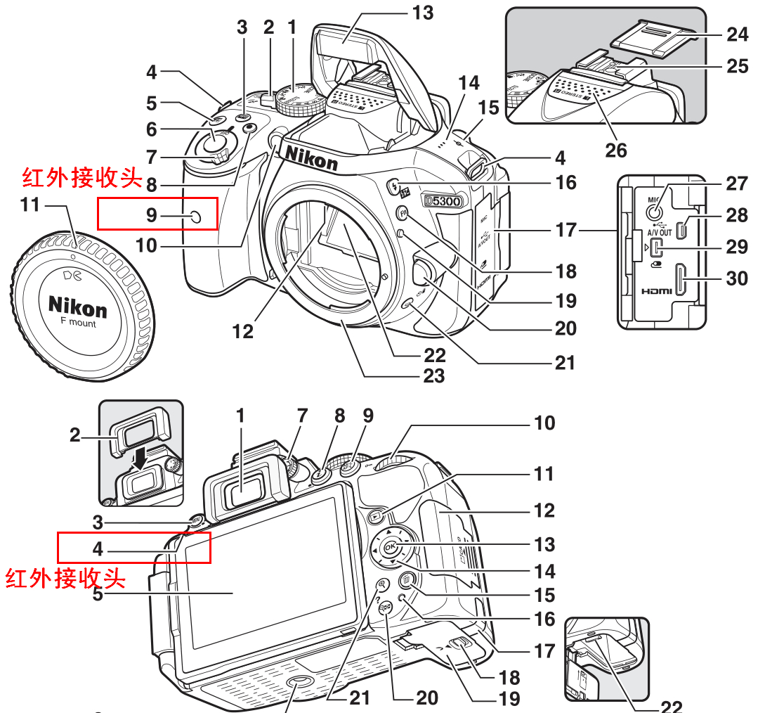
对于实际的脉冲时间,不用特别的精确,误差不要太大就行,最好使用示波器测量以下脉冲的时间。对于制作好的遥控器,只需要在相机周围按下按钮就可实现遥控快门。相机机身的红外接收头前后各有一个,可以方便在不同的位置遥控。如下图所示。
总结
这款尼康ML-L3红外遥控器的实现原理非常简单,可扩展性强,可以根据需要自己添加功能,如添加固定时间间隔拍摄,固定张数拍摄,用于拍摄制作延时视频所需要的图片素材。当然,也可以使用手机上的遥控器来实现这个功能。
代码获取
以上代码已经开源在Github和Gitee平台,地址如下。
- Github开源地址:
https://github.com/whik/nikon-wireless-remote-control-ML-L3-DIY.git - Gitee开源地址 :
https://gitee.com/whik/nikon-wireless-remote-control-ML-L3-DIY.git
没有使用代码托管平台的朋友,可以在公众号后台回复【尼康遥控器】也可以获取代码。
参考资料
文中的ML-L3拆解图,Arduino代码参考自以下链接内容。
- http://www.bigmike.it/ircontrol/
- https://www.sbprojects.net/projects/nikon/index.php
- https://learn.adafruit.com/ir-sensor/making-an-intervalometer
推荐阅读
- 我的个人博客:www.wangchaochao.top
- 我的公众号:mcu149