infrared sensor
The remote controller sends the modulated signal through the infrared LED, and the infrared receiving module on the development board receives the infrared rays from the remote controller.
Simplex asynchronous, 940nm wavelength (there is also a 250nm N, visible light), EC communication standard.
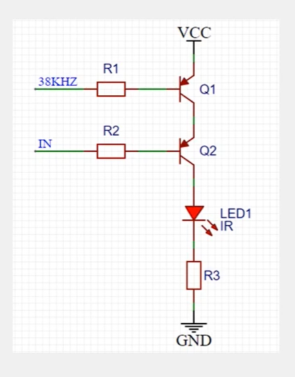
38KHz: Infrared frequency.
IN: Square wave sent.
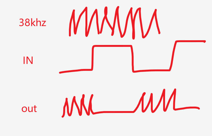
The infrared receiving module will automatically filter out the In part for us.

Idle state: OUT outputs high level.
Send high level: OUT outputs high level.
Send low level: OUT outputs low level, which means there is data.
38kHz belongs to the underlying information, so the protocol layer does not show it, similar to the encapsulation of the class.
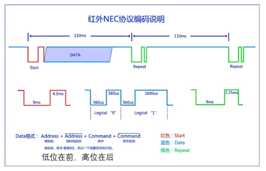
9ms low + 4.5ms high: start.
Followed by four bytes of data. Inverse code is used for data verification.
560us low + 560us high means 0, 560us low + 1690us high means 1. The last high level at the end must be followed by a falling edge to indicate termination.
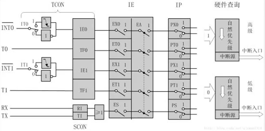
It is very inefficient to scan all the time, so the out is connected to the external interrupt.
external interruption
void main(){


    LCD_Init();
    LCD_ShowString(1,1,"A");
    IT0=1;
    IE0=0;
    EX0=1;
    EA=1;
    PX0=1;
    while(1){


        LCD_ShowNum(2,1,num,2);
    }
}

void Int0_Routine() interrupt 0 {


    num++;
}
The interrupt is connected with the third button P3^2, so when the button 3 is pressed, the falling edge will trigger the interrupt.
If it is changed to a low level trigger, that is, IT0=0, the trigger will always be triggered when the button is pressed.
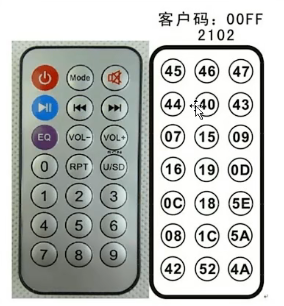
The received data will be displayed on the digital tube with 2 binary digits. Here, the buttons on the remote control are not displayed on the digital tube after a few presses. Please pay attention. The point is only to see whether the different signal microcontrollers of the remote control can distinguish and identify them.
//ired.h
#ifndef _ired_H
#define _ired_H

#include "public.h"

//管脚定义
sbit IRED=P3^2;

//声明变量
extern u8 gired_data[4];


//函数声明
void ired_init(void);

#endif

//ired.c
#include "ired.h"

u8 gired_data[4];//存储4个字节接收码(地址码+地址反码+控制码+控制反码)

/*******************************************************************************
* 函 数 名         : ired_init
* 函数功能		   : 红外端口初始化函数,外部中断0配置
* 输    入         : 无
* 输    出         : 无
*******************************************************************************/
void ired_init(void)
{


	IT0=1;	//下降沿触发
	EX0=1;	//打开中断0允许
	EA=1;	//打开总中断
	IRED=1;	//初始化端口
}

void ired() interrupt 0	//外部中断0服务函数
{


	u8 ired_high_time=0;
	u16 time_cnt=0;
	u8 i=0,j=0;
	//引导信号有9ms的低电平和4.5ms的高电平,先把这两部分读掉,并且如果太长时间引导信号没有发生相应的变化就先跳出,省的系统死机。我们给引导信号10ms和5ms的机会。
	if(IRED==0)
	{


		time_cnt=1000;
		while((!IRED)&&(time_cnt))//等待引导信号9ms低电平结束,若超过10ms强制退出
		{


			delay_10us(1);//延时约10us
			time_cnt--;
			if(time_cnt==0)return;
		}
		if(IRED)//引导信号9ms低电平已过,进入4.5ms高电平
		{


			time_cnt=500;
			while(IRED&&time_cnt)//等待引导信号4.5ms高电平结束,若超过5ms强制退出
			{


				delay_10us(1);
				time_cnt--;
				if(time_cnt==0)return;
			}
            //接下来是读取地址、地址反码、控制、控制反码。
			for(i=0;i<4;i++)//循环4次,读取4个字节数据
			{


				for(j=0;j<8;j++)//循环8次读取每位数据即一个字节
				{


					time_cnt=600;
					while((IRED==0)&&time_cnt)//等待数据1或0前面的0.56ms结束,若超过6ms强制退出
					{


						delay_10us(1);
						time_cnt--;
						if(time_cnt==0)return;
					}
					time_cnt=20;
					while(IRED)//等待数据1或0后面的高电平结束,若超过2ms强制退出
					{


						delay_10us(10);//约0.1ms
						ired_high_time++;
						if(ired_high_time>20)return;
					}
					gired_data[i]>>=1;//先读取的为低位,然后是高位
					if(ired_high_time>=8)//如果高电平时间大于0.8ms,数据则为1,否则为0
						gired_data[i]|=0x80;//最高位赋1
					ired_high_time=0;//重新清零,等待下一次计算时间
				}
			}
		}
		if(gired_data[2]!=~gired_data[3])//校验控制码与反码,错误则清空后返回
		{


			for(i=0;i<4;i++)
				gired_data[i]=0;
			return;
		}
	}
}
main.c:
void main()
{


	u8 ired_buf[3];

	ired_init();//红外初始化

	while(1)
	{


		ired_buf[0]=gsmg_code[gired_data[2]/16];//将控制码高4位转换为数码管段码
		ired_buf[1]=gsmg_code[gired_data[2]%16];//将控制码低4位转换为数码管段码
		ired_buf[2]=0X76;//显示H的段码
		smg_display(ired_buf,6);
	}
}