Recently I found a netizen made a foreign
RAID diagram to explain
The users have to admire the whimsy
Several drinking fountains and buckets
Vividly put complex issues to resolve
▼▼▼

>>>>
1. Standalone:
The first figure is well understood, PC we use every day on the use of such data read mode. Data stored in a hard disk, and only one hard disk, then naturally we can only read data from the hard disk.
>>>>
2. Hot swap:
The second map is not difficult to understand, at the ground the bucket. The so-called Hot swap is conceptually similar to the hot backup. It reads data in a manner similar Standalone, the only difference is that there is a spare hard disk ready. Once the hard disk is being used there is a problem, it will be replaced on the spare hard to avoid losses. But this way there are also some drawbacks, such as a hard disk replacement requires time, which for many companies is fatal.
>>>>
3. Cluster:
The third figure is what does that mean? Cluster is a cluster of meaning. You can be seen as two separate PC, the user can go to the fountain to the left to get the data, you can also go to the fountain to get the right data, but this is more a waste of hardware resources in the enterprise where multiple servers can not make offer the same data and the same services.
>>>>
4. RAID 0:
Commonly referred to as a band, stripe data using mapping techniques specific properties. Its advantage is the speed of read and write data faster, but there is no redundancy, if one disk (physical) damage, all of the data can not be used.
>>>>
5. RAID 1:
It is called "disk image" fault-tolerant configuration. In which the data is written to a hard disk, while the other one is also copied to the hard disk. In this manner prevents data loss caused by damage to the hard disk, but even two hard disk storage space which corresponds to the size of only one hard disk. And I / O transfer rate can not be improved, the dispenser outlet is not increased or decreased more.
>>>>
6. RAID 5:
Independent distributed parity disk structure, a buffer commonly used technique to reduce the asymmetry properties. Take the form of RAID 5, I / O transfer rate will be greatly improved, and a bad hard drive does not matter, as well as other spare hard disk. Another advantage of RAID 5 is that it allows "hot swap", which means that if one disk in the array fails, the disk can be exchanged with a new disk without shutting down the server or NAS, do not interrupt or are accessing the NAS server user.
>>>>
7. RAID 0+1:
This is what we often say that RAID 10, which is a combination of RAID 1 and 0. It combines the mirrored RAID 1 and RAID 0 stripe. It provides the best performance, but also very expensive, requires twice the other RAID level.
Or eat fish?
Capacity and performance of traditional user's worries
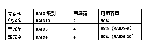
After reading the above figures and explain concepts related to RAID is not clear out? In fact, in addition to these, RAID above, there are other forms, such as RAID 2, RAID 4, RAID 7 and so on, but after so many years of development, RAID form has been basically fixed, mainstream form of so few: RAID 10, RAID 5, RAID 6 (. 5 is similar to the RAID) .
From a performance standpoint, the influence due to the write penalty, RAID 10 write performance is generally better than RAID 5 and RAID 6, and therefore the performance critical applications, customers want RAID 10 by way of the bottom . However, from the dimension disk utilization, RAID 10 available capacity of only 50%, but also the most uneconomical (see below).
Therefore, the face of such fish and bear's paw problems, usually customers will adopt the following measures:
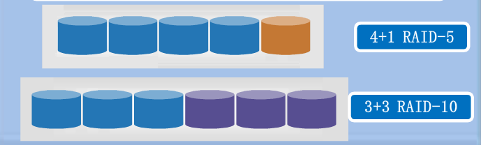
➤ assumed that the customer bought a total of 11 hard disk of the same size (e.g. 600G 15K, the nominal random IOPS 180), in order to obtain better writing properties, taking a combination of six disks RAID10 constructed, the write IOPS 540, to mount database applications, the capacity utilization rate of 50%, which is 1.8TB (here ignored 1024 and 1000 disk capacity count difference). The remaining 5 construction group RAID5 hard to get more capacity, write IOPS 225, 2.4TB capacity, to mount the backup application.
In this way achieve a balance of performance and capacity, but also has some drawbacks, due to the segmentation of a lot of disk groups, IO resources between the disk group can not be shared . So there was a pooling of resources to deal with technical solutions.

The obvious advantage of the pool of RAID. Back to the previous example, the database may be busy during the day, the backup usually work at night, there is a time difference between the two, but any application can use a hard disk IOPS 11 blocks. Even with the highest RAID5 space utilization, there are random IOPS 495, the basic guarantee database applications. Some users also want to pursue the limit IOPS, because this time delay will be minimal, they adopt strategies RAID 10 random IOPS up to 990, database applications running cool night run back up quickly, but sacrifice some capacity.
Now we can see that the disk block-level virtualization to solve the problem of data silos, balanced all the front-end IO to disk. It is not look perfect? In fact, this way still can not obtain a good balance between performance and capacity (regardless of RAID 5 or RAID 10 or sacrifice some capacity or performance)