EDITORIAL words
When using keys, if the keys much, we can directly buttons and FPGA connected, but if the keys more time, if it continues to be used directly to make buttons and FPGA connected to the case, will be a substantial increase in consumption of FPGA ports in order to reduce the consumption of FPGA port, we can key designed in the form of a matrix. Next, the dream-wing brothers and everyone will learn the principles and the drive scanning circuit mode the keyboard.
Project requirements
Design 4 * 4 matrix keyboard key scanning module , the correct parse key value .
Principle matrix keyboard
Can be known from the figure, the matrix rows of the keyboard row (row) and col (column) of intersection are connected by a key. The traditional method of a port of a button, to achieve the 16 keys, you need 16 ports, and now this matrix design of the keyboard, 16 keys, requires only eight ports, 16 ports to do if you use a keyboard matrix, then , 64 keys can be identified, port utilization is much better than traditional designs, if so desired small button, you can select a traditional button design, if desired, then more keys, the keyboard can be employed such a matrix design. And we are now in a scanning method as an example to introduce the principle of matrix keyboard.
First col (column) to an FPGA matrix keyboard scanning signal output, the row (row) matrix keyboard is fed back to the FPGA input signal, for detecting which key is pressed, a schematic diagram is as follows:

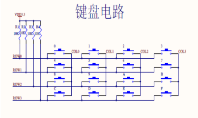 As shown, FPGA given scan signal COL [3: 0], COL = 4'b0111, wait for the next clock cycle COL = 4'b1011, and then wait for the next clock cycle COL = 4'b1101, and then the next and so on clock cycle COL = 4'b1110, and then wait for the next clock cycle COL = 4'b0111, COL is such a continuous cycle, to a matrix keyboard scanning signal is active low, when the FPGA to a matrix keyboard scanning signal is simultaneously COL, FPGA also a feedback signal ROW to the FPGA in a detection matrix of the keyboard, for example, if the matrix 9 keyboard keys are pressed:
When COL = 4'b0111, ROW = 4'b1111;
When COL = 4'b1011, ROW = 4'b1111;
When COL = 4'b1101, ROW = 4'b1011;
When COL = 4'b1110, ROW = 4'b1111;
Someone asked, why, when COL = 4'b1101 time, ROW = 4'b1011 it? We are now in a matrix keyboard circuitry to analyze this reason, as shown above:
9 when key is pressed, the key circuit 9 will be turned on, COL scanning circuit starts scanning when the scanning COL [. 1], because of the key 9, the circuit is turned on, COL [ voltage 1] is equal to the ROW [2] of the voltage, so there will be time when COL = 4'b1101 ROW = 4'b1011 (frequency sweep signal is probably about 1K).
Typically the key switch is a mechanical switch elasticity, when the mechanical contacts open, is closed, since the spring action of a mechanical contact, a key switch is not turned on immediately stably when closed, will not look upon opening son off. Thus at the moment and closed off all accompanied by a series of shake measures in order not to produce this phenomenon do is key debounce.
Jitter is determined by the length of time the key mechanical properties, generally 5ms ~ 10ms. This is a very important time parameters should be used on many occasions. Closing the length of time the key is stabilization is determined by the key operation of an operator, typically a few tenths to a few seconds (usually the key press time is greater than 20ms) . Key jitter causes a key is misread many times. To ensure that the CPU primary key for closing only one process, the key must be removed jitter. Reads the status of the key when the key is closed stable, and must be stable before the release button is determined to be processed.
Then we can use these phenomena to identify key design a circuit.
Architecture design
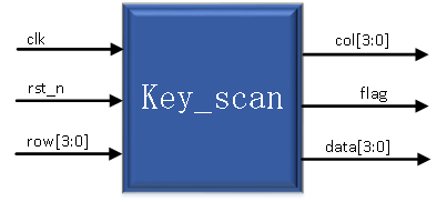
According to the principle analysis, we design the architecture is as follows:
Module Features
| Module name |
Functional Description |
| key_scan |
Detecting the key value |
Port Description top module
| Port Name |
Port Description |
| clk |
System clock input |
| rst_n |
System reset |
| row |
Matrix keyboard row line |
| data |
Key value |
| flag |
Key value is valid (spikes) |
| col |
Matrix keyboard column lines |
Code explanation
Key_scan module code
| /**************************************************** * Engineer: Dream Brother Wing * QQ : 761664056 Of The function Module1 * : detected values of the key matrix of the keyboard *****************************************************/ 000 module key_scan ( CLK 001 , // system clock input Rst_n 002 , // system reset Row 003 , // keyboard matrix row lines In Flag 004 , // output value valid flag (spikes) Data 005 , // key value 006 col // keyboard matrix column lines 007 ); 008 // system input 009 INPUT CLK ; // system clock input 010 INPUT RST_N ; // reset 011 INPUT [ . 3 : 0 ] Row ; // row line matrix keyboard 012 // system output 013 Output REG In Flag ; // output value valid flag (spikes) 014 Output REG [ . 3 : 0 ] Data ; // key value 015 output reg [3:0] col;//矩阵键盘的列线 016 017 reg clk_1K;//1K的时钟 018 reg [20:0] count;//计数器 019 020 always @ (posedge clk or negedge rst_n) 021 begin 022 if (!rst_n) 023 begin 024 clk_1K <= 1; 025 count <= 0; 026 end 027 else 028 if (count < 24999) // 50000分频,得出1K的时钟 029 count <= count + 1; 030 else 031 begin 032 count <= 0; 033 clk_1K <= ~clk_1K; 034 end 035 end 036 037 reg [4:0] cnt_time;//按键按下的时间 038 reg [1:0] state;//状态寄存器 039 reg [7:0] row_col;//按键对应的行列值 040 041 always @ (posedge clk_1K or negedge rst_n) 042 begin 043 if (!rst_n)//复位时,将中间寄存器和输出置0 044 begin 045 flag <= 0; 046 state <= 0; 047 cnt_time <= 0; 048 row_col <= 0; 049 col <= 4'b0000; 050 end 051 else 052 begin 053 case (state) 054 0 : begin 055 if (row != 4'b1111)//当有按键按下时,开始计数,只有 056 begin //一直按下20ms才会被当做有效的按键 057 if (cnt_time < 19) 058 cnt_time <= cnt_time + 1; 059 else 060 begin 061 cnt_time <= 0; 062 state <= 1; 063 col <= 4'b1110;//扫描的初始值 064 end 065 end 066 else 067 cnt_time <= 0; 068 end 069 070 1 : begin 071 if (row!=4'b1111) 072 begin 073 row_col <= {row,col};//当检测出来时,把行列线的值存起来 074 flag <= 1; //拉高有效标志 075 state <= 2; 076 col <= 4'b0000;//用于判断按键是否抬起来 077 end 078 else 079 begin 080 col <= {col[2:0],col[3]};//没有检测出来时,换成下一列 081 end //扫描 082 end 083 084 2 : begin 085 if (row == 4'b1111)//当按键释放20ms以后才会被当做释放 086 begin //跳转到0状态进行新的按键值的检测 087 if (cnt_time < 19) 088 begin 089 cnt_time <= cnt_time + 1; 090 flag <= 0; 091 end 092 else 093 begin 094 cnt_time <= 0; 095 state <= 0; 096 col <= 4'b0000; 097 end 098 end 099 else 100 begin 101 cnt_time <= 0; 102 flag <= 0; 103 end 104 end 105 106 default : state <= 0; 107 endcase 108 end 109 end 110 111 always @ (*) 112 begin 113 if(!rst_n) 114 begin 115 data =0; 116 end 117 else 118 begin 119 case(row_col) 120 8'b1110_1110: data =0; 121 8'b1110_1101: data =1; //每一个按键的位置被行线和列线唯一确定 122 8'b1110_1011: data =2; //根据行线和列线的值给出对应的按键值 123 8'b1110_0111: data =3; 124 8'b1101_1110: data =4; 125 8'b1101_1101: data =5; 126 8'b1101_1011: data =6; 127 8'b1101_0111: data =7; 128 8'b1011_1110: data =8; 129 8'b1011_1101: data =9; 130 8'b1011_1011: data =10; 131 8'b1011_0111: data =11; 132 8'b0111_1110: data =12; 133 8'b0111_1101: data =13; 134 8'b0111_1011: data =14; 135 8'b0111_0111: data =15; 136 default : data = 0; 137 endcase 138 end 139 end 140 141 endmodule |
测试代码
| /**************************************************** * Engineer : 梦翼师兄 * QQ : 761664056 * The module function:矩阵键盘测试代码 *****************************************************/ 000 `timescale 1ns/1ps 001 002 module key_scan_tb; 003 //系统输入 004 reg clk;//系统时钟输入 005 reg rst_n;//系统复位 006 reg [3:0] row;//矩阵键盘的行线 007 //系统输出 008 wire flag;//输出值有效标志(尖峰脉冲) 009 wire [3:0] data;//按键值 010 wire [3:0] col;//矩阵键盘的列线 011 012 initial 013 begin 014 clk=0; 015 rst_n=0; 016 # 1000.1 rst_n=1; 017 end 018 019 always #10 clk=~clk;//50M的时钟 020 021 reg [4:0] pnumber;//按键值 022 023 initial 024 begin 025 pnumber=16;//无按键按下 026 # 6000000 pnumber=1; 027 # 3000000 pnumber=16; 028 # 6000000 pnumber=1; 029 # 3000000 pnumber=16; 030 # 6000000 pnumber=1;//模仿了一段抖动 031 # 3000000 pnumber=16; 032 # 6000000 pnumber=1; 033 # 3000000 pnumber=16; 034 # 6000000 pnumber=1; 035 # 21000000 036 pnumber=1;//按键“1”按下了21ms 037 # 3000000 pnumber=16; 038 # 6000000 pnumber=1; 039 # 3000000 pnumber=16; 040 # 6000000 pnumber=1;//模仿释放时的抖动 041 # 3000000 pnumber=16; 042 # 6000000 pnumber=1; 043 # 3000000 pnumber=16; 044 # 6000000 pnumber=1; 045 # 3000000 pnumber=16; 046 # 60000000 047 pnumber=2; 048 # 3000000 pnumber=16; 049 # 6000000 pnumber=2; 050 # 3000000 pnumber=16; 051 # 6000000 pnumber=2; 052 # 3000000 pnumber=16;//按下时的抖动 053 # 6000000 pnumber=2; 054 # 21000000 055 pnumber=2;//按下21ms 056 # 3000000 pnumber=16; 057 # 6000000 pnumber=2; 058 # 3000000 pnumber=16; 059 # 6000000 pnumber=2; 060 # 3000000 pnumber=16;//释放时的抖动 061 # 6000000 pnumber=2; 062 # 3000000 pnumber=16; 063 # 6000000 pnumber=2; 064 # 3000000 pnumber=16; 065 end 066 067 //当有按键按下时,行线和列线的变化 068 always @(*) 069 case (pnumber) 070 0: row = {1'b1,1'b1,1'b1,col[0]}; 071 1: row = {1'b1,1'b1,1'b1,col[1]}; 072 2: row = {1'b1,1'b1,1'b1,col[2]}; 073 3: row = {1'b1,1'b1,1'b1,col[3]}; 074 4: row = {1'b1,1'b1,col[0],1'b1}; 075 5: row = {1'b1,1'b1,col[1],1'b1}; 076 6: row = {1'b1,1'b1,col[2],1'b1}; 077 7: row = {1'b1,1'b1,col[3],1'b1}; 078 8: row = {1'b1,col[0],1'b1,1'b1}; 079 9: row = {1'b1,col[1],1'b1,1'b1}; 080 10: row = {1'b1,col[2],1'b1,1'b1}; 081 11: row = {1'b1,col[3],1'b1,1'b1}; 082 12: row = {col[0],1'b1,1'b1,1'b1}; 083 13: row = {col[1],1'b1,1'b1,1'b1}; 084 14: row = {col[2],1'b1,1'b1,1'b1}; 085 15: row = {col[3],1'b1,1'b1,1'b1}; 086 16: row = 4'b1111; 087 default: row = 4'b1111; 088 endcase 089 090 //实例化key_scan模块 091 key_scan key_scan ( 092 .clk(clk), //系统时钟输入 093 .rst_n(rst_n), //系统复位 094 .row(row),//矩阵键盘的行线 095 .flag(flag),//输出值有效标志(尖峰脉冲) 096 .data(data),//按键值 097 .col(col)//矩阵键盘的列线 098 ); 099 100 endmodule |
在测试模块的中的68行至88行,描述了矩阵键盘的响应方式。假如:“5”被按下,“5”处在row[1]和col[1]的位置,只有当col[1]为低电平时,row[1]才能检测到低电平,并且row=4’b1101唯一确定了按键的位置。
在测试中,模拟了数字“1”以及数字“2”按下以及释放时的抖动。
仿真分析
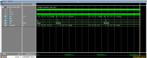
从波形中,我们可以看出:按键稳定前,pnumber有一段抖动,稳定之后,data变成了按键值,释放时pnumber又有一段抖动,两段抖动data都没有发生改变。