Task One:
- Networking Requirements
All switches run OSPF, and the entire AS is divided into three areas.
Switch A and Switch B as ABR to forward routing information between areas.
After configuration, all switches can learn routes to every network segment in the AS.
Experimental topology is as follows: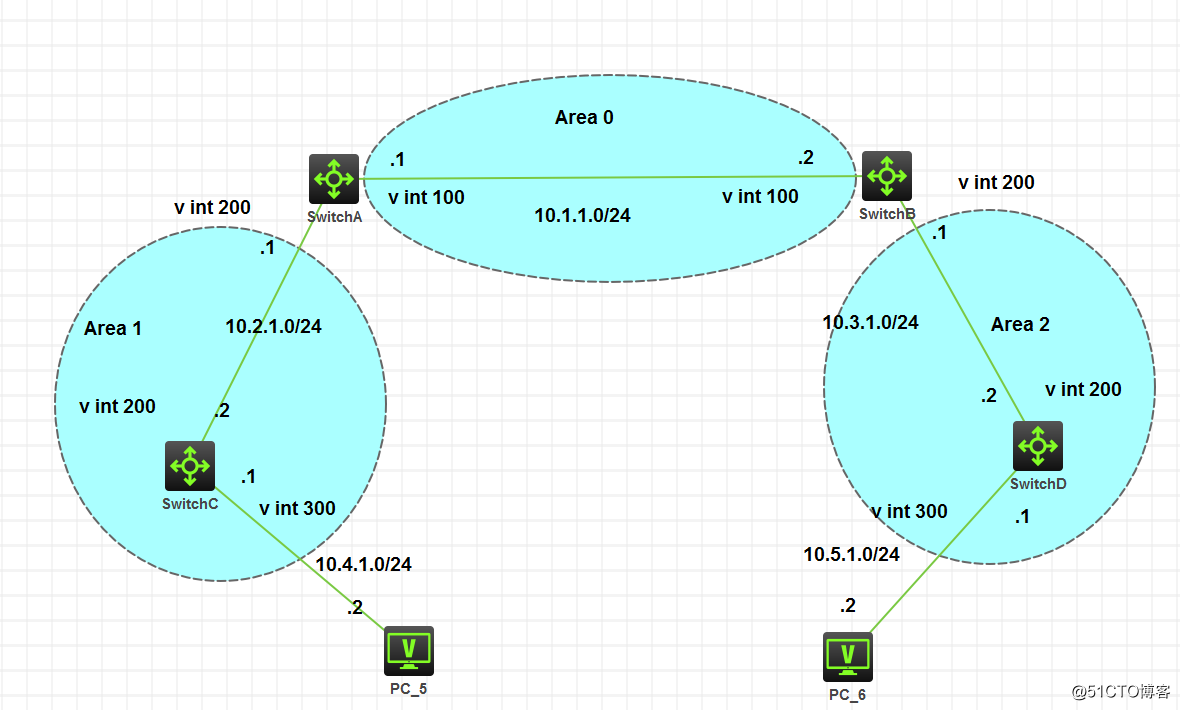
Experimental configuration is as follows:
- 配置步骤
(1) 配置各接口的 IP 地址(略)
例SwitchB:
<H3C>sys
[H3C]hostname SwitchB
[SwitchB]vlan 100
[SwitchB-vlan100]port g 1/0/10
[SwitchB-vlan100]quit
[SwitchB]vlan 200
[SwitchB-vlan200]port g 1/0/20
[SwitchB-vlan200]quit
[SwitchB]inter vlan 100
[SwitchB-Vlan-interface100]ip add 10.1.1.2 24
[SwitchB-Vlan-interface100]quit
[SwitchB]inter vlan 200
[SwitchB-Vlan-interface200]ip add 10.3.1.1 24
[SwitchB-Vlan-interface200]quit
[SwitchB]
(2) 配置 OSPF 基本配置
配置 Switch A。
<SwitchA> system-view
[SwitchA] router id 10.2.1.1
[SwitchA] ospf
[SwitchA-ospf-1] area 0
[SwitchA-ospf-1-area-0.0.0.0] network 10.1.1.0 0.0.0.255
[SwitchA-ospf-1-area-0.0.0.0] quit
[SwitchA-ospf-1] area 1
[SwitchA-ospf-1-area-0.0.0.1] network 10.2.1.0 0.0.0.255
[SwitchA-ospf-1-area-0.0.0.1] quit
[SwitchA-ospf-1] quit
配置 Switch B。
<SwitchB> system-view
[SwitchB] router id 10.3.1.1
[SwitchB] ospf
[SwitchB-ospf-1] area 0
[SwitchB-ospf-1-area-0.0.0.0] network 10.1.1.0 0.0.0.255
[SwitchB-ospf-1-area-0.0.0.0] quit
[SwitchB-ospf-1] area 2
[SwitchB-ospf-1-area-0.0.0.2] network 10.3.1.0 0.0.0.255
[SwitchB-ospf-1-area-0.0.0.2] quit
[SwitchB-ospf-1] quit
#配置 Switch C。
<SwitchC> system-view
[SwitchC] router id 10.4.1.1
[SwitchC] ospf
[SwitchC-ospf-1] area 1
[SwitchC-ospf-1-area-0.0.0.1] network 10.2.1.0 0.0.0.255
[SwitchC-ospf-1-area-0.0.0.1] network 10.4.1.0 0.0.0.255
[SwitchC-ospf-1-area-0.0.0.1] quit
[SwitchC-ospf-1] quit
配置 Switch D。
<SwitchD> system-view
[SwitchD] router id 10.5.1.1
[SwitchD] ospf
[SwitchD-ospf-1] area 2
[SwitchD-ospf-1-area-0.0.0.2] network 10.3.1.0 0.0.0.255
[SwitchD-ospf-1-area-0.0.0.2] network 10.5.1.0 0.0.0.255
[SwitchD-ospf-1-area-0.0.0.2] quit
[SwitchD-ospf-1] quit
- 验证配置
#查看 Switch A 的 OSPF 邻居。
[SwitchA] display ospf peer verbose
查看 Switch A 的 OSPF 路由信息。
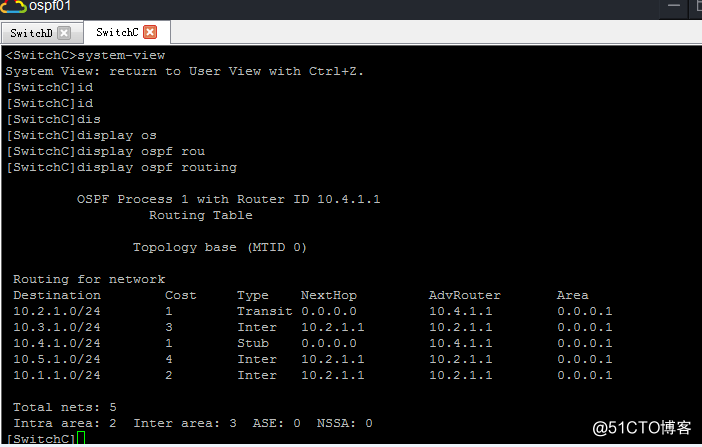
[SwitchA] display ospf routing
查看 Switch D 的 OSPF 路由信息。
[SwitchD] display ospf routing
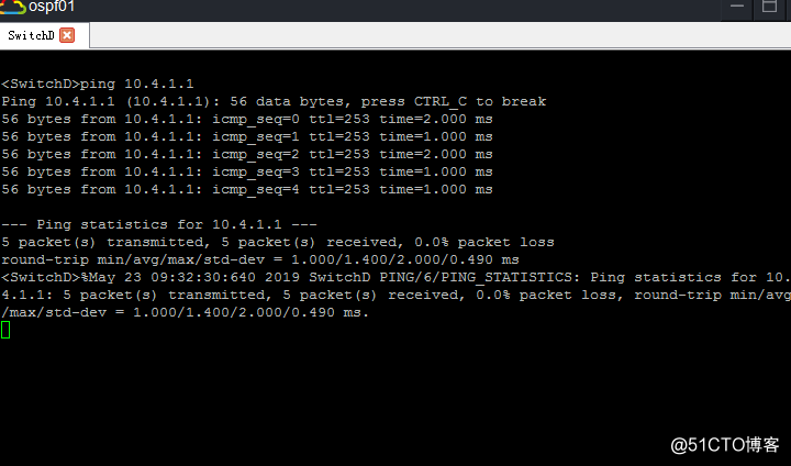
在 Switch D 上使用 Ping 进行测试连通性。
[SwitchD] ping 10.4.1.1
实验结果如下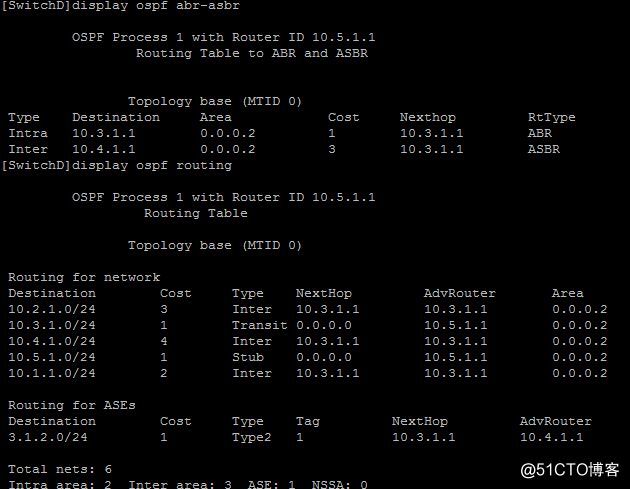
任务二:
配置OSPF引入自治系统外部路由
- 组网需求
所有的交换机都运行 OSPF,整个自治系统划分为 3 个区域。
其中 Switch A 和 Switch B 作为 ABR 来转发区域之间的路由。
在 Switch C 上配置为 ASBR 引入外部路由(静态路由),且路由信息可正确的在 AS 内传播。
实验拓扑图如下: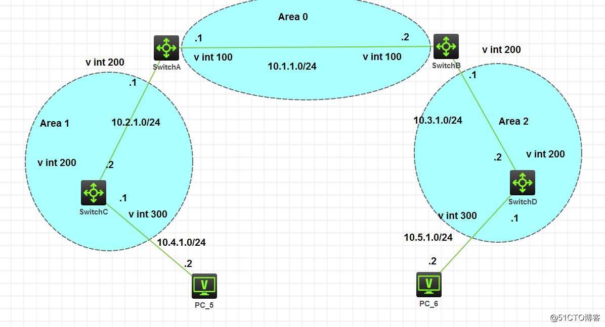
- 配置步骤
(1) 配置各接口的 IP 地址(略)
(2) 配置OSPF(同前例 1.13.1 )
(3) 配置引入自治系统外部路由
在 Switch C 上配置一条到目的网段 3.1.2.0/24 的静态路由。
<SwitchC> system-view
[SwitchC] ip route-static 3.1.2.1 24 10.4.1.2
在 Switch C 上配置 OSPF 引入静态路由。
[SwitchC] ospf 1
[SwitchC-ospf-1] import-route static - 验证配置
查看 Switch D 的 ABR/ASBR 信息。
<SwitchD> display ospf abr-asbr
查看 Switch D 的 OSPF 路由表。
<SwitchD> display ospf routing
实验结果如下: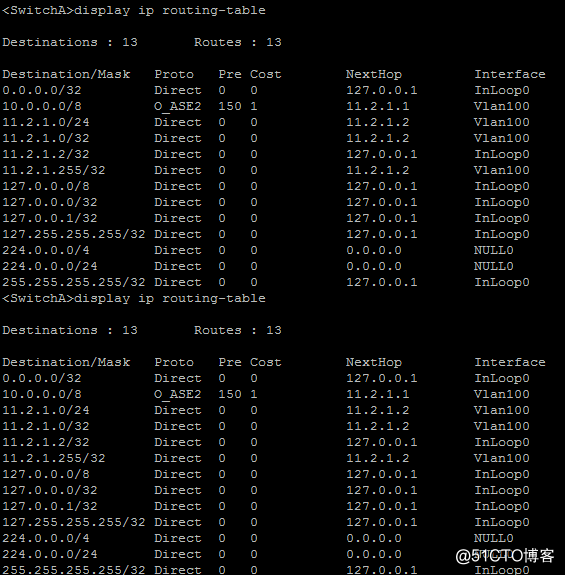
实验三:
1.13.3 配置OSPF发布聚合路由 - 组网需求
Switch A 和 Switch B 位于 AS 200 内,AS 200 内使用 OSPF 作为 IGP 协议。
Switch C、Switch D 和 Switch E 位于 AS 100 内,AS 100 内使用 OSPF 作为 IGP 协议。
Switch B 和 Switch C 之间建立 EBGP 连接,配置 BGP 引入 OSPF 和直连路由,配置 OSPF
进程引入 BGP 路由。
为了减小 Switch A 的路由表规模,在 Switch B 上配置路由聚合,只发布聚合后的路由
10.0.0.0/8。
实验拓扑图如下: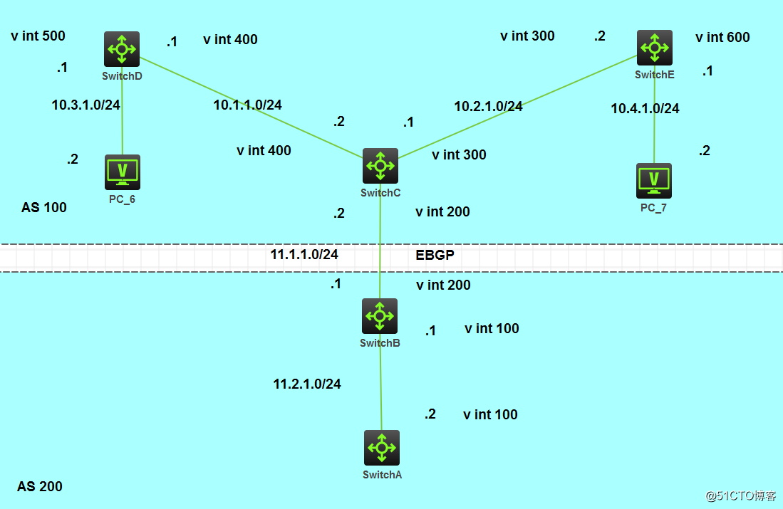
配置过程如下: - 配置步骤
(1) 配置接口的 IP 地址(略)
(2) 配置 OSPF
配置 Switch A。
<SwitchA> system-view
[SwitchA] router id 11.2.1.2
[SwitchA] ospf
[SwitchA-ospf-1] area 0
[SwitchA-ospf-1-area-0.0.0.0] network 11.2.1.0 0.0.0.255
[SwitchA-ospf-1-area-0.0.0.0] quit
[SwitchA-ospf-1] quit
配置 Switch B。
<SwitchB> system-view
[SwitchB] router id 11.2.1.1
[SwitchB] ospf
[SwitchB-ospf-1] area 0
[SwitchB-ospf-1-area-0.0.0.0] network 11.2.1.0 0.0.0.255
[SwitchB-ospf-1-area-0.0.0.0] quit
[SwitchB-ospf-1] quit
配置 Switch C。
<SwitchC> system-view
[SwitchC] router id 11.1.1.2
[SwitchC] ospf
[SwitchC-ospf-1] area 0
[SwitchC-ospf-1-area-0.0.0.0] network 10.1.1.0 0.0.0.255
[SwitchC-ospf-1-area-0.0.0.0] network 10.2.1.0 0.0.0.255
[SwitchC-ospf-1-area-0.0.0.0] quit
[SwitchC-ospf-1] quit
配置 Switch D。
<SwitchD> system-view
[SwitchD] router id 10.3.1.1
[SwitchD] ospf
[SwitchD-ospf-1] area 0
[SwitchD-ospf-1-area-0.0.0.0] network 10.1.1.0 0.0.0.255
[SwitchD-ospf-1-area-0.0.0.0] network 10.3.1.0 0.0.0.255
[SwitchD-ospf-1-area-0.0.0.0] quit
配置 Switch E。
<SwitchE> system-view
[SwitchE] router id 10.4.1.1
[SwitchE] ospf
[SwitchE-ospf-1] area 0
[SwitchE-ospf-1-area-0.0.0.0] network 10.2.1.0 0.0.0.255
[SwitchE-ospf-1-area-0.0.0.0] network 10.4.1.0 0.0.0.255
[SwitchE-ospf-1-area-0.0.0.0] quit
[SwitchE-ospf-1] quit
(3) 配置 BGP,引入 OSPF 和直连路由
配置 Switch B。
[SwitchB] bgp 200
[SwitchB-bgp] peer 11.1.1.2 as 100
[SwitchB-bgp] address-family ipv4 unicast
[SwitchB-bgp-ipv4] import-route ospf
[SwitchB-bgp-ipv4] import-route direct
[SwitchB-bgp-ipv4] peer 11.1.1.2 enable #注意不要少了这句
[SwitchB-bgp-ipv4] quit
[SwitchB-bgp] quit
配置 Switch C。
[SwitchC] bgp 100
[SwitchC-bgp] peer 11.1.1.1 as 200
[SwitchC-bgp] address-family ipv4 unicast
[SwitchC-bgp-ipv4] import-route ospf
[SwitchC-bgp-ipv4] import-route direct
[SwitchC-bgp-ipv4] peer 11.1.1.1 enable # careful not less the phrase
[SwitchC-BGP-ipv4] quit
[SwitchC-BGP] quit
(4) arranged OSPF into BGP routes on Switch B and Switch C
configuration OSPF into BGP routes on Switch B.
[SwitchB] OSPF
[OSPF--SwitchB. 1] Import-BGP route
configured OSPF into BGP routes on Switch C.
[SwitchC] OSPF
[OSPF--SwitchC. 1] Import-route BGP
routing table of SwitchA.
[SwitchA] display ip routing-table
(5) arranged on the route aggregation Switch B, only the summary route 10.0.0.0/8.
[SwitchB-ospf-1] asbr -summary 10.0.0.0 8
See Switch A's routing table.
[SwitchA] display ip routing-table