The development process of the 4+1 view model of software architecture:
1. first proposed
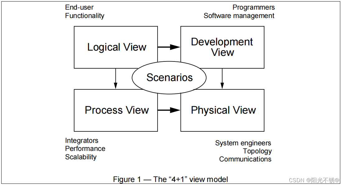
In November 1995, Philippe Kruchten's paper "The 4+1 View Model of Architecture" published in "IEEE Software" first proposed the 4+1 views as shown in the figure, which are: logical view, development view, process view, and physical view. and scene view.
in,
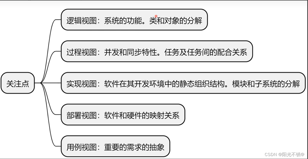
(1)Logical view’sThe stakeholder is the end user, and the focus is the system Function, what services should the system provide to users. (Use: Class diagram can be used to describe)
(2)Development view (implementation view)The stakeholders are developers and project managers, the focus is the organization, and it can be repeated Usability, portability, product line. For very small systems, the logical view and the development view may be almost the same, so there is no need to describe them separately. (Usage: You can use component diagrams to describe)
(3)Process View (Process View) The stakeholders are system designers and integrators, and the focus is on some non-functional Requirements, such as: performance, availability, software fault tolerance, integrity. From the logical view, you can analyze the processes and describe them in words, but you don't need to draw graphics. If there is only one processor and only one process or program, the process view can be omitted (use: text description, sequence diagram, activity diagram, state diagram, etc. to display).
(4)Physical view (deployment view)The stakeholders are system designers, and the focus is scalability and performance. Availability. It establishes the mapping relationship between software and hardware and considers the non-functional requirements of the system. (Usage: Deployment diagram can be used for display)
Note: It can be seen that the focus of the process view and the physical view are somewhat similar. They both focus on the non-functional requirements of the system, such as performance, availability, etc., but their methods and perspectives of consideration are completely different. Process view considers the decomposition of system processes, which processes should be designed, which objects should be placed in which processes to run, in this way Issues that improve system performance and availability. The physical view considers which software is deployed on which hardware to solve system performance and availability problems.
The stakeholders of (5)Scenario View are end users and developers, and the focus is understandability. A scenario is an abstraction of the most important requirements. (Usage: Use use case diagram description)
2. Evolution

After evolution, it is just more detailed and specific. The logical view and process view have not changed, the development view has become an implementation view, the physical view has become a deployment view, and the scenario view has become a use case view.
3. Association between views
3.1 From logical view to process view

The function of the logical view relationship system is specifically to identify the relationship between objects. From logical view to process view, it is to identify the concurrency of objects.
3.2 From logical view to development view

The logical view itself identifies the objects and classes of the system. The development view is based on the logical view and identifies system modules and subsystems through classes, as well as the relationship between modules and subsystems, thereby forming a development view.
3.3 From process view to physical view

4. Cut the model
Not all software architectures require a complete 4+1 view. The useless views can be omitted when describing the architecture. For example: if there is only one processor and only one process or program, the process view can be omitted. . For very small systems, the logical view and the development view may be almost the same, so there is no need to describe them separately.
But the scene view is useful in any situation.
5. Summary
| view | logic | process | develop | physics | Scenes |
|---|---|---|---|---|---|
| components | kind | Task | model, child lineage |
node | Walk, Screenplay |
| Connector | 关联, 继入, Inclusion |
Rendez-vous, News, Dissemination, RPC, etc. |
Compilation dependency, "with" clause, "include" |
communication media, LAN, WAN, bus, etc. |
|
| container | class category | process | Subsystem (Library) | Physics subsystem | Web |
| stakeholders | end user | System Designer, Integrator |
Developer, Project Manager |
system designer | End User Developer |
| focus point | Function | Performance, Availability, Transferability, Completeness |
Organization, Reusability, Portability, Product Line |
Scalability Performance, Availability |
understandability |
| Tool support | Rose | UNAS/SALE DADS |
Apex, SoDA | UNAS, Openview DADS |
Rose |
6. Architecture design documentsDirectory reference
1. Document introduction
1.1 Purpose of document
1.2 Reading Guide
2. Logical architecture view
2.1 Architecture design
2.2 Interface design
2.3 Use case view
2.4 Business data flow diagram
2.5 Important process sequence diagram
3. Run the architecture view
4. Physical architecture view
4.1 Operating environment
4.1.1 Hardware environment
4.1.2 Software environment
4.2 System deployment diagram
5. Data architecture view
5.1 Selection of persistence mechanism
5.2 Database table design
6. Develop architectural views
6.1 Module division
6.2 Project division
6.3APP project
6.3.1 Development environment
6.3.2 Directory structure
6.3.3 Third-party libraries
6.4api project (same as above)
over