Welcome to YuleZhang's quantum computing column. This column revolves around "Quantum Information and Quantum Computing" edited by Chen Hanwu. It pursues the Feynman learning method and uses vivid language and own understanding to dismantle this book as much as possible, so as to continue to To consolidate and improve, welcome to study with me and look forward to your valuable suggestions!
Table of contents
I. Introduction
We mentioned earlier the magical properties of quantumsuperposition and entanglement. It is precisely because of these properties that the quantum world is always Covered with a veil, even though the fog has been cleared away, her "no makeup" is still not visible. Moreover, when these quantum states are transmitted on the quantum channel, they will also be affected by environmental noise and self-coherence, causing the information to be forwarded to be "unrecognizable". Therefore, similar to the processing method of traditional channels (such as Hamming code error correction, etc.), we also add error correction coding to the quantum channel to ensure that we Accuracy and reliability of transmitted data.

2. Classic error correction coding
Why not just learn the quantum error correction coding method directly, because quantum error correction is developed on the basis of classical error correction, and it is just an appropriate expansion. After understanding this, I believe you have mastered half of the content of quantum error correction. Let's take a look at what the "shoulders of giants" look like.
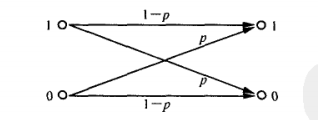
Let’s first imagine the simplest scenario. You want to send a message to your girlfriend who is far away. Assuming that this channel is easy to be interfered, we assume that the probability that you send 1 and it receives 0 and that you send 0 and receive 1 is p p p, that is to say, the probability that your girlfriend receives the correct information is 1 − p 1-p 1−p. As shown below.
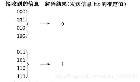
Then in order to ensure a certain error tolerance rate, in order for your female ticket to receive the information correctly. We will send 1 b i t 1bit 1bit Repeat the data three times before sending Go out, that is, when you send 000, it means you are sending 0, and when you send 111, it means you are sending 1. After your female vote receives the information, use themajority decision method to decode it, as shown in the figure
This processing can indeed Most of the errors are corrected, but there are also "fish that slip through the net", that is, when two or more bits in the sent data are affected by noise, then the female vote has completely misunderstood it. Now let's calculate the probability of this happening. Two bit errors are C 3 2 p 2 ( 1 − p ) C_3^2p^2(1-p) C32p2(1−p), if all three bits are wrong, it means C 3 3 p 3 C_3^3p^ 3 C33p3,设 p = 0.01 p=0.01 p=0.01 then it is wrong The probability is
C 3 2 p 2 ( 1 − p ) + C 3 3 p 3 = ( 3 − 2 p ) p 2 = 0.000298 < 0.01 C_3^2p^2(1-p )+C_3^3p^3 = (3-2p)p^2=0.000298<0.01 C32p2(1−p)+C33p3=(3−2p)p2=0.000298<0.01
You can see through three Bit repetition encoding significantly reduces the bit error rate.
3. Quantum error correction coding
The "protagonist" is about to appear - Quantum error correction coding, through logic gate operation< /span>Errors in quantum channel transmission generally occur in the following three situations! ! ! to achieve quantum error correction. Pay attention heremajority decision methodCombined with the above
- bit flip error
- phase reversal error
- Both bit and phase inversion errors occur
whereas classic bit transfer only considers bit reversal errors. Moreover, it is obvious that the third situation is the result of the simultaneous action of the first and second types, and the corresponding error correction can also be combined.
3.1 Quantum error correction coding of bit inversion channel
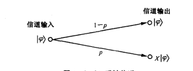
This situation is very similar to the inversion of the classic channel and is relatively easy to handle. The significant difference between the two is that the input signal in the channel becomes ∣ ψ = α ∣ 0 + β ∣ 1 |\psi =\alpha|0 +\beta| 1 ∣ψ⟩=α∣0⟩+β∣1⟩. Regarding the circumstances, there is also an explanation 1 − p 1-p 1−The probability of p is received without error, that is, it is output as is. And there p p The probability of p is reversed during the transmission process.
Hey, stop here. The reversal in quantum can just be used X X X gate, that is to say there are p p The probability of p makes the female vote get X ∣ ψ X|\psi The results of X∣ψ are summarized. This is the picture below
Similarly, we repeat the transmitted information three times. Note that the encoding remains linear. So we have the following formula, and the actual transmission content is ∣ ψ = α ∣ 000 + β ∣ 111 |\psi =\alpha|000 +\beta| 111 ∣ψ⟩=α∣000⟩+β∣111⟩
| qubit | coding |
|---|---|
| |0⟩ | |0⟩|0⟩|0⟩=|000⟩ |
| |1⟩ | |1⟩|1⟩|1⟩=|111⟩ |
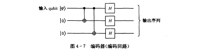
So what does a quantum circuit that realizes information repetition look like? Please look at the picture below
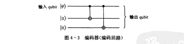
You can see that there are two control NOT gates in the picture. When the input is input< a i=2> ∣ ψ |\psi When ∣ψ is 1, the 0 bits in the second and third bits are both When the reversal occurs, we get ∣ 111 |111 ∣111⟩ . Same reason and import ∣ ψ ⟩ |\psi⟩ When ∣ψ is 0, the 0 bits in the second and third bits are not The reversal occurs and we get ∣ 000 |000 ∣000 , you’re done, this is the encoder.
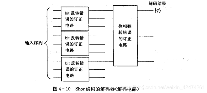
Let’s consider the function of the decoder. Is it exactly the same as the traditional channel (the majority decision method)! So how to design a quantum circuit? Scientists have helped us solve this problem. Its composition is also a controlled NOT gate. Let’s take a look at its structure
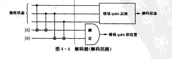
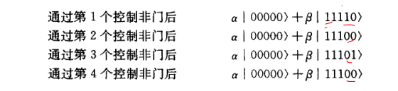
You can see that the receiver adds 2 qubits Auxiliary information, initialize it to ∣ 00 |00 ∣00 , same as received The 3qubit information is sent to the decoder together. If the transmitted information is not reversed, then after 4 controlled NOT gate calculations, its status will change as follows in sequence
You only need to measure the last 2 qubits to accurately determine the occurrence of an error. s position. The corresponding relationship is as follows
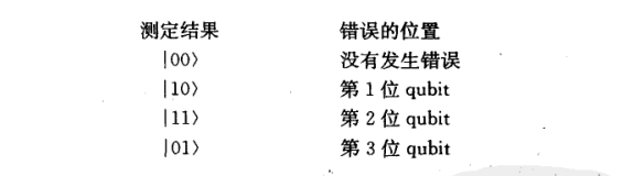
When we find the location of the error bit, we can pass X − G a t e X-Gate X−Gate Automatic correction of calculation inversion Wrong.
It is obvious that the above decoding process is somewhat abstract. A specific example will be given below to help understand. The content to be sent is ∣ ψ = α ∣ 0 + β ∣ 1 |\psi =\alpha|0 +\beta|1 ∣ψ⟩=α∣0⟩+β∣1 , using the above encoding ∣ ∣ ∣ = α ∣ 000 + β ∣ 111 |\psi =\alpha|000 +\beta|111 ∣ψ⟩=α∣000⟩+β∣111 . Assume that a reversal error occurs in the second qubit during the transmission, that is, the receiver receives α ∣ 010 + β ∣ 101 \alpha|010 +\beta|101 < /span>α∣010⟩+β∣101 . Don't worry, feed this sequence into the decoder (Figure 4-4). Through a series of operations that control the NOT gate, the calculated result at the dotted line is α ∣ 01011 + β ∣ 10111 = ( α ∣ 010 + β ∣ 101 ) ∣ 11 \alpha|01011 +\beta|10111 =(\alpha|010 +\beta|101 )|11 α∣01011⟩+β∣10111⟩=(α∣010⟩+β∣101 ⟩)∣11 beta|^2=1 ∣α∣2+∣β∣2=The probability of 1 is determined to be ∣ 11 |11 ∣11 , look up the table and find that Corresponding to the second bit error, implement X − G a t e X-Gate X−Gate can get the correct result.
The error of bit inversion ends here. To sum up, it is first encoded by three repetition encoder, and then transmitted. After receiving the information, auxiliary bits are added and sent to the decoder. Look up the 2 auxiliary output bits of the decoder in the table to find the corresponding error position, and finally X − G a t e X-Gate X−GateConfirmation completed!
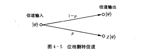
3.2 Quantum error correction coding for phase inversion channels
With the above basis of bit inversion, we can quickly make it clear that the information we send will be 1 − p 1-p 1−The probability of p is not changed by interference during transmission, and there is also p p The probability of p occurring during transmission is reversed.
Stop here for a moment. Can phase inversion be used? Z − G a t e Z-Gate WITH−Gate to express it, so In the same way, the following figure is obtained (phase inversion channel)
Then, the input ∣ ψ = α ∣ 0 + β ∣ 1 | \psi =\alpha|0 +\beta|1 ∣ψ⟩=α∣0⟩+β∣1⟩Feeding machine ( Part 4-3), arrived at∣ψ⟩=α∣000⟩+β∣111 . Transmit it through the phase inversion channel. If the first qubit is phase inverted, the information received by the receiver is α ∣ 000 − β ∣ 111 \alpha|000 -\beta|111 α∣000⟩−β∣111 . For this situation, it is obvious that the majority decision method in bit reversal cannot be used. It obviously has no countermeasures for such problems. Let’s review H H
H门(Hadamard变换)
H = 1 2 [ 1 1 1 − 1 ] H=\frac{1}{\sqrt{2}} \left[ \begin{matrix} 1 & 1\\ 1 & -1\\ \end{matrix} \right] H=21[111−1]
H门有如下的性质
H ∗ H = H 2 = 1 2 [ 1 1 1 − 1 ] [ 1 1 1 − 1 ] = [ 1 0 0 1 ] = I H*H=H^2=\frac{1}{2} \left[ \begin{matrix} 1 & 1\\ 1 & -1\\ \end{matrix} \right] \left[ \begin{matrix} 1 & 1\\ 1 & -1\\ \end{matrix} \right]= \left[ \begin{matrix} 1 & 0\\ 0 & 1\\ \end{matrix} \right]=I H∗H=H2=21[111−1][111−1]=[1001]=I
H Z H = 1 2 [ 1 1 1 − 1 ] [ 1 0 0 − 1 ] [ 1 1 1 − 1 ] = [ 0 1 1 0 ] = X HZH=\frac{1}{2} \left[ \begin{matrix} 1 & 1\\ 1 & -1\\ \end{matrix} \right] \left[ \begin{matrix} 1 & 0\\ 0 & -1\\ \end{matrix} \right] \left[ \begin{matrix} 1 & 1\\ 1 & -1\\ \end{matrix} \right]=\left[ \begin{matrix} 0 & 1\\ 1 & 0\\ \end{matrix} \right]=X HZH=21[111−1][100−1][111−1]=[0110]=< a i=0>
IDisplay one position square, X X X represents a bit inversion gate. Therefore, the bit phase inversion error can be converted into a bit inversion error, and then the bit inversion channel error correction code can be used to correct the error. Obtain the correct data, and the summary is shown in Figure 4-6.
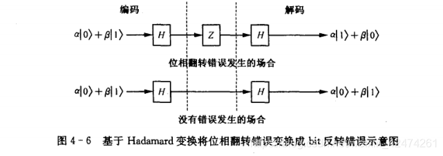
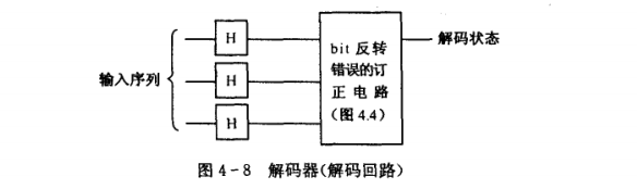
The dotted lines represent different locations of the information. The left side is the sender, the middle is during transmission, and the right side is the receiver. Let’s take a look at the schematic diagrams of the encoder and decoder (Figure 4-7 and Figure 4-8).
I believe it is very intuitive. In order to facilitate understanding, let me give an example and go through this process in detail. For the convenience of description, first define the state using the following method ∣ + |+ ∣+⟩sum ∣ − ⟩ |- ⟩ ∣−⟩:
∣ + ⟩ = H ∣ 0 ⟩ = 1 2 [ 1 1 1 − 1 ] [ 1 0 ] = 1 2 [ 1 1 ] |+⟩=H|0⟩=\frac{1}{\sqrt{2}} \left[\begin{matrix} 1 & 1\\ 1 &-1 \end{matrix}\right]\left[\begin{matrix} 1 \\ 0 \end{matrix}\right]=\frac{1}{\sqrt{2}}\left[\begin{matrix} 1 \\ 1\end{matrix}\right] ∣+⟩=H∣0⟩=21[111−1][10]=21[11]
∣ − ⟩ = H ∣ 1 ⟩ = 1 2 [ 1 1 1 − 1 ] [ 0 1 ] = 1 2 [ 1 − 1 ] |-⟩=H|1⟩=\frac{1}{\sqrt{2}} \left[\begin{matrix} 1 & 1\\ 1 &-1 \end{matrix}\right]\left[\begin{matrix} 0\\ 1 \end{matrix}\right]=\frac{1}{\sqrt{2}}\left[\begin{matrix} 1 \\ -1\end{matrix}\right] ∣−⟩=H∣1⟩=21[111−1][01]=21[1−1]
The old rule is that the information is repeated three times through the repetition code, and then each bit is done H H H gate operation can obtain the following 3qubit superposition state.
α H ∣ 0 H ∣ 0 H ∣ 0 + β H ∣ 1 H ∣ 1 H ∣ 1 = α ∣ + + + + β ∣ − − − \alpha H|0 H|0 H|0 +\beta H|1 H|1 H|1 =\alpha |+++ +\beta |--- αH∣0⟩H∣0⟩H∣0⟩+βH∣1⟩H∣1⟩H∣1⟩=α∣+++⟩+β∣−−−
The above is the result after encoding by the encoder. Now we need to convert this The result is sent to the other party! However, during the transmission process, someone maliciously sabotaged it, causing a phase reversal error in the second qubit. I want to mislead you, haha, causing the other party to receive it α ∣ + − + + β ∣ − + − \alpha|+-+ +\beta |-+- α∣+−+⟩+β∣−+− . But fortunately we have the decoder in Figure 4-8. First send the obtained content to H H The H gate performs operations. According to the following calculation formula, we get: H H The result of the H gate operation is α ∣ 010 + β ∣ 101 \alpha |010 +\beta|101 < /span>α∣010⟩+β∣101⟩
H ∣ + ⟩ = H ( H ∣ 0 ⟩ ) = ∣ 0 ⟩ H ∣ − ⟩ = H ( H ∣ 1 ⟩ ) = ∣ 1 ⟩ H|+⟩=H(H|0⟩)=|0⟩ \\ H|-⟩=H(H|1⟩)=|1⟩ H∣+⟩=H(H∣0⟩)=∣0⟩H∣−⟩=H(H∣1⟩)=∣1
The following will be converted into bit To invert the problem, just send it to the decoder shown in Figure 4-4 and then perform the inversion operation. To sum up, compared to the bit inversion circuit, phase inversion adds H H The H door cleverly transforms the problem, so that the original information can finally be revealed.
3.3 Inversion occurs when bit and bit are the same
With the above foreshadowing, this situation should be relatively obvious. Our idea is to correct the bit inversion error first, and then convert the phase error into a bit inversion error< /span> H H to get the correct information. With this idea in mind, let’s take a look at what the encoder looks like. correct the bit inversion error again, and finally
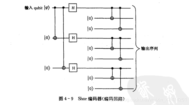
HThe door and the previous one are easy to understand, just like the phase reversal. Then, three repetitions of operations were added to each bit before output, mainly to be able to directly correctbit inversion errors.
At this point, someone may ask why the first three repeated qubits cannot be directly used to correct bit inversion errorsHere. Remember that the bit phase inversion error mentioned above eventually turns into a bit inversion error? Therefore, the first three repeated qubits are used to give the bit phase inversion processingbit inversion< /span> The above is the main content of this study. The content is somewhat abstract and needs to be understood and consolidated repeatedly! . bit is the same as the bit It can be seen from the picture that, consistent with our above description, the bit error is corrected for each bit first, and then directly By feeding in the bit phase inversion correction circuit of 4-8, you can successfully solve the error correction circuit where an error occurs when the Let’s take a look at the schematic diagram of the decoder. correction operations. phase errorThe reserved repetition code is reserved for completing