Table of contents
1. The importance of rendering order
2. Rendering order of Unity Shader
1. What is transparency testing?
1. What is transparency blending?
5. Turn on the translucency effect of deep writing
6. ShaderLab’s mixing commands
1. Mixing equations and parameters
7. Transparency effect of double-sided rendering
1. Double-sided rendering for transparency test
2. Double-sided rendering with transparency mixing
Preface
To achieve transparency in real-time rendering, you usually control its Transparency Channel (Alpha Channel) when rendering the model. After transparent mixing is turned on, each fragment has a transparency attribute in addition to its color value and depth value. When the transparency is 1, it means that the pixel is completely opaque. When it is 0, it means it is completely transparent and will not be displayed.
We have two methods to achieve transparency in Unity: 1. Transparency test. This method cannot achieve a true translucent effect. ;2. Transparency blending.
Let’s talk about the rendering order, that is, when the scene contains many models, in what order should they be rendered. For opaque objects, you can get the correct sorting effect without considering the rendering order. This is due to the powerful depth buffer (depth buffer, also called z- buffer) exists. The depth buffer is used to solve visibility problems. It can determine which parts of an object are rendered in front and which parts are obscured by other objects. The basic idea is to determine the distance of the fragment from the camera based on the value in the depth cache. When rendering a fragment, you need to compare its depth value with the value that already exists in the depth cache (provided that depth is turned on test), if its value is farther from the camera, then it should not be rendered to the screen (obstructed by the object); if its value is closer to the camera, this fragment should overwrite the value in the color buffer at this time pixel value and updates its depth to the depth buffer (provided depth writing (ZWrite On) is turned on). But if you want to achieve a transparent effect, you must use transparency mixing, and turn off depth writing at this time.
1. The importance of rendering order
As mentioned earlier, for transparency blending technology, depth writing needs to be turned off, so we need to carefully handle the rendering order of transparent objects. If depth writing is not turned off, the object behind a translucent object can be seen. However, because the translucent surface is judged to be closer to the camera during the depth test, the objects behind it will be eliminated, and the semi-transparent object cannot be seen through. Transparent surfaces allow you to see objects behind them. But this also destroys the working mechanism of the depth cache, and turning off depth writing makes the rendering order very important.
As shown in Figure 8.1, A is translucent and B is opaque. Let’s discuss the impact of rendering order on the results.
- Render B first, then A. B is an opaque object and will enable depth testing and depth writing, so B will write to the color buffer and depth buffer. Then rendering A, we find that A is closer to the camera, so we will use the transparency of A and the color of B in the color buffer to mix to get the correct translucency effect.
- Render A first, then render B. A is a translucent object. When rendering A, it will be written directly to the color buffer, but since depth writing is turned off, A will not modify the depth buffer. Then when rendering B, B will perform a depth test, but the depth cache does not have the information of A. B thinks that there is nothing blocking it in front of it, and then writes directly to the color buffer, causing B to directly overwrite A's color. It looks like B appears in front of A, but this is wrong.
As shown in 8.2, if both objects are translucent, an error will occur if A is rendered first and then B is rendered, resulting in a translucent structure with B in front of A. Therefore, translucent objects must also comply with a certain rendering order.

Based on the above two examples, the rendering engine generally sorts the objects first and then renders them. Commonly used methods are:
- First render all opaque objects and enable their depth testing and depth writing.
- Sort the translucent objects according to their distance from the camera, then render these translucent objects in order from back to front, turn on their depth test, and turn off depth writing.
- In the case of mutual overlap and coverage (Figure 8.3, 8.4) (a correct sorting order cannot be obtained), the method of dividing the grid can be used. Consider splitting complex models into multiple sub-models that can be sequenced independently.
- If you don't want to split the mesh, you can make the transparency channel softer so that the interleaving does not look very obvious; you can also use the translucency effect with depth writing turned on to approximate the translucency of the object.

2. Rendering order of Unity Shader
Unity provides a render queue solution. We can use the SubShader's Queue tag to decide which queue our model will belong to.
| name | Queue index number | describe |
| Background | 1000 | This rendering queue will be rendered before other queues to draw objects that need to be drawn on the background. |
| Geometry | 2000 | The default rendering queue, most objects can use this queue. Opaque objects use this sequence |
| AlphaTest | 2450 | Objects that require transparency testing. It would be more efficient to render this queue after the opaque objects are rendered. |
| Transparent | 3000 | The objects in the queue will be rendered sequentially from back to front after all Geometry and AlphaTest objects are rendered. Any object that uses transparency blending (such as a Shader with depth writing turned off) should use this queue. |
| Overlay | 4000 | Used to achieve some overlay effects. The last rendered object. |
Achieving transparency effects through transparency testing or transparency mixing should include code similar to the following:
//透明度测试
SubShader{
    Tags{"Queue" = "AlphaTest"}
    Pass{...}
}

//透明度混合
SubShader{
    Tags{"Queue" = "Transparent"}
    Pass{
        ZWrite Off //用于关闭深度写入,也可以放在SubShader里面,这意味着该SubShader下的所有Pass都会关闭深度写入
    }
}
3. Transparency test
1. What is transparency testing?
Transparency test: As long as the transparency of a fragment does not meet the conditions (usually less than a certain threshold), the corresponding fragment will be discarded. The discarded fragment will not be processed in any way and will not have any impact on the color buffer, otherwise it will be processed in the same way as ordinary opaque objects. According to the description, we found that the transparency test does not require turning off deep writing, but the effect produced is also very extreme, either completely transparent or completely opaque.
We generally use the clip function for transparency testing. clip is a function in CG: void clip(float4 x), the parameters inside can also be float3, float2, float2, float1, float. If any component of the given parameter is negative, the output color of the current pixel will be discarded, equivalent to the following code:
void clip(float4 x)
{
    if(any(x<0))
        discard;
}
2. Practice
In this section we want to achieve the following effects:

Shader "MyShader/Chapter 8/Alpha Test" {
	Properties {
		_Color ("Color Tint", Color) = (1, 1, 1, 1)
		_MainTex ("Main Tex", 2D) = "white" {}
		//_Cutoff 参数用于决定我们调用 clip 进行透明度测试时使用的判断条件,它的范围是[O, 1],这是因为纹理像素的透明度就是在此范围内。
		_Cutoff ("Alpha Cutoff", Range(0, 1)) = 0.5
	}
	SubShader {
		//把Queue标签设置为AlphaTest
		//把IgnoreProjector设置为true,意味着这个Shader不会受到投影器(Properties)的影响
		//RenderType标签可以让Unity把这个Shader归入到提前定义的组(TransparentCutout组),以指明该Shader是一个使用了透明度测试的Shader
		//使用了透明度测试的Shader都应该在SubShader设置三个标签
		Tags {"Queue"="AlphaTest" "IgnoreProjector"="True" "RenderType"="TransparentCutout"}

		Pass {
			//LightMode用于定义该Pass在Unity的光照流水线中的角色。只有正确定义LightMode,才能正确得到一些Unity的内置光照,如_LightColor0
			Tags { "LightMode"="ForwardBase" }

			CGPROGRAM

			#pragma vertex vert
			#pragma fragment frag

			#include "Lighting.cginc"

			fixed4 _Color;
			sampler2D _MainTex;
			float4 _MainTex_ST;
			fixed _Cutoff;//由于_Cutoff 范围在[O I], 因此我们可以使用 fixed精度来存储它。

			struct a2v {
				float4 vertex : POSITION;
				float3 normal : NORMAL;
				float4 texcoord : TEXCOORD0;
			};

			struct v2f {
				float4 pos : SV_POSITION;
				float3 worldNormal : TEXCOORD0;
				float3 worldPos : TEXCOORD1;
				float2 uv : TEXCOORD2;
			};

			v2f vert(a2v v) {
				v2f o;
				o.pos = UnityObjectToClipPos(v.vertex);

				o.worldNormal = UnityObjectToWorldNormal(v.normal);

				o.worldPos = mul(unity_ObjectToWorld, v.vertex).xyz;

				o.uv = TRANSFORM_TEX(v.texcoord, _MainTex);

				return o;
			}

			fixed4 frag(v2f i) : SV_Target {
				fixed3 worldNormal = normalize(i.worldNormal);
				fixed3 worldLightDir = normalize(UnityWorldSpaceLightDir(i.worldPos));

				fixed4 texColor = tex2D(_MainTex, i.uv);

				// 透明测试
				clip (texColor.a - _Cutoff);//如果texColor.a - _Cutoff为负数,就舍弃改片元的输出。
				// 相当于下面的代码
				//if ((texColor.a - _Cutoff) < 0.0) {
				//	discard;
				//}

				fixed3 albedo = texColor.rgb * _Color.rgb;

				fixed3 ambient = UNITY_LIGHTMODEL_AMBIENT.xyz * albedo;

				fixed3 diffuse = _LightColor0.rgb * albedo * max(0, dot(worldNormal, worldLightDir));

				return fixed4(ambient + diffuse, 1.0);
			}

			ENDCG
		}
	}
	FallBack "Transparent/Cutout/VertexLit"//设置回调,这个回调在后面第九章节会讲
}
Most of this part of the code has been learned in the previous chapters, except for the declaration of the _Cutoff variable, the setting of the label in the SubShader, and the transparency test (clip function) in the fragment shader.
We can achieve different levels of elimination by adjusting the Alpha cutoff value of the material panel (that is, the threshold of the transparency test).
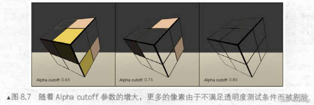
4. Transparency Mixing
1. What is transparency blending?
Transparency blending: This method can get a true translucent effect. It will use the transparency of the current fragment as the mixing factor to mix with the color value already stored in the color buffer to obtain a new color. However, transparency blending requires turning off depth writing, which makes us very careful about the rendering order of objects.
In order to blend, we need to use the blending command provided by Unity - Blend. Blend is a command provided by Unity to set the blend mode. Below are the semantics of some Blend commands.
| Semantics | describe |
|---|---|
| Blend off | Turn off blending |
| Blend SrcFactor DstFactor | Turn on blending and set the blending factor. The source color (the color produced by this fragment) is multiplied by SrcFactor, and the destination color (The color that already exists in the color buffer) will be multiplied by DstFactor, and then the two are added together and then stored in the color buffer. |
| Blend SrcFactor DstFactor, SrcFactorA DstFactorA |
Pretty much the same as above, just using a different factor to mix the transparency channel |
| BlendOp BlendOperation | Instead of simply adding the source color and the target color and blending them, use BlendOperation to perform other operations on them. |
The following practice uses the second semantics.
2. Practice
The effect achieved is as follows:
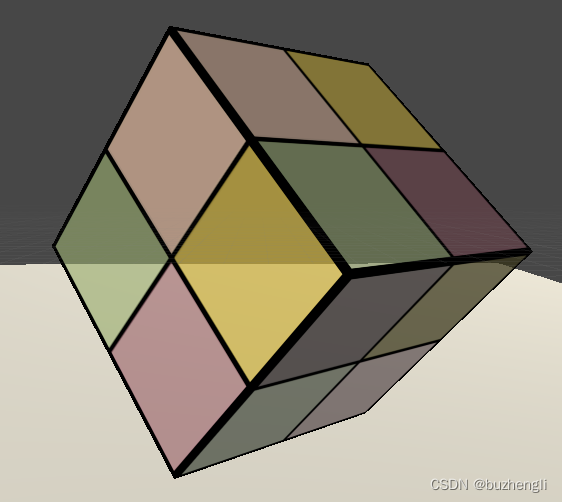
Shader "MyShader/Chapter 8/Alpha Blend" {
	Properties {
		_Color ("Color Tint", Color) = (1, 1, 1, 1)
		_MainTex ("Main Tex", 2D) = "white" {}
		//我们使用一个新的属性_AlphaScale 来替代原先的_Cutoff 属性。_AlphaScale用于在透明纹理的基础上控制整体的透明度。
		_AlphaScale ("Alpha Scale", Range(0, 1)) = 1
	}
	SubShader {
		//把Queue标签设置为Alphaparent
		//把IgnoreProjector设置为true,意味着这个Shader不会受到投影器(Properties)的影响
		//RenderType标签可以让Unity把这个Shader归入到提前定义的组(这里就是Transparent组),以指明该Shader是一个使用了透明度混合的Shader
		//使用了透明度测试的Shader都应该在SubShader设置这三个标签
		Tags {"Queue"="Transparent" "IgnoreProjector"="True" "RenderType"="Transparent"}

		Pass {
			Tags { "LightMode"="ForwardBase" }
			//为透明度混合进行合适的混合状态设置
			//关闭深度写入
			ZWrite Off
			//使用了Blend SrcFactor DstFactor语义
			//把源颜色(该片元着色器产生的颜色)的混合因子SrcFactor设为SrcAlpha, 而目标颜色(已经存在于颜色缓冲中的颜色)的混合因子 DstFactor设为 OneMinusSrcAlpha 。
			Blend SrcAlpha OneMinusSrcAlpha//这部分在下面 六 会讲到

			CGPROGRAM

			#pragma vertex vert
			#pragma fragment frag

			#include "Lighting.cginc"

			fixed4 _Color;
			sampler2D _MainTex;
			float4 _MainTex_ST;
			fixed _AlphaScale;

			struct a2v {
				float4 vertex : POSITION;
				float3 normal : NORMAL;
				float4 texcoord : TEXCOORD0;
			};

			struct v2f {
				float4 pos : SV_POSITION;
				float3 worldNormal : TEXCOORD0;
				float3 worldPos : TEXCOORD1;
				float2 uv : TEXCOORD2;
			};

			v2f vert(a2v v) {
				v2f o;
				o.pos = UnityObjectToClipPos(v.vertex);

				o.worldNormal = UnityObjectToWorldNormal(v.normal);

				o.worldPos = mul(unity_ObjectToWorld, v.vertex).xyz;

				o.uv = TRANSFORM_TEX(v.texcoord, _MainTex);

				return o;
			}

			fixed4 frag(v2f i) : SV_Target {
				fixed3 worldNormal = normalize(i.worldNormal);
				fixed3 worldLightDir = normalize(UnityWorldSpaceLightDir(i.worldPos));

				fixed4 texColor = tex2D(_MainTex, i.uv);

				fixed3 albedo = texColor.rgb * _Color.rgb;

				fixed3 ambient = UNITY_LIGHTMODEL_AMBIENT.xyz * albedo;

				fixed3 diffuse = _LightColor0.rgb * albedo * max(0, dot(worldNormal, worldLightDir));

				//设置了该片元着色器返回值中的透明通道,它是纹理像素的透明通道和材质参数_AlphaScale的乘积。
				return fixed4(ambient + diffuse, texColor.a * _AlphaScale);
			}

			ENDCG
		}
	}
	FallBack "Transparent/VertexLit"
}
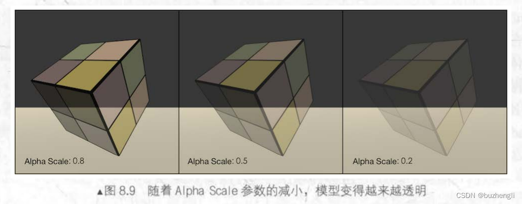
The picture below shows the translucency effect under different Alpha Scale parameters.
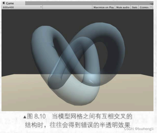
But when there are intersecting structures between the grids, you will often get the wrong translucent effect (as shown below). Let's solve this problem
5. Turn on the translucency effect of deep writing
1. Implementation method
In the above we gave a case of incorrect ordering caused by turning off deep writing. One solution is touse two Pass to render the model:
- The first Pass enables depth writing, but does not output color. Its purpose is only to write the depth value of the model into the depth buffer.
- The second Pass performs normal transparency mixing. Because the previous Pass has obtained the correct depth information on a pixel-by-pixel basis, this Pass can perform transparent rendering according to the pixel-level depth sorting results.
The disadvantage of this method is that using one more Pass will have a certain impact on performance. Using this method, you can get the following effect. It can be seen that the effect of blending the model with the background behind can still be achieved, but there will not be any translucency effect between the interior of the model.

2. Practice
It is also very simple to implement. We only need to add a Pass statement in front of the original Pass based on the previous transparency mixing code.
Shader "Unity Shaders Book/Chapter 8/Alpha Blending With ZWrite" {
	Properties {
		_Color ("Color Tint", Color) = (1, 1, 1, 1)
		_MainTex ("Main Tex", 2D) = "white" {}
		_AlphaScale ("Alpha Scale", Range(0, 1)) = 1
	}
	SubShader {
		Tags {"Queue"="Transparent" "IgnoreProjector"="True" "RenderType"="Transparent"}

		// 新加的Pass语句
		Pass {
			ZWrite On
			ColorMask 0
		}

		Pass {
			......//和前面的代码内容一样
			}

			ENDCG
		}
	}
	FallBack "Transparent/VertexLit"
}
The purpose of this newly added Pass is just to write the depth information of the model into the depth buffer, thereby eliminating fragments in the model that are occluded by itself. ZWrite On is used to enable deep writing. ColorMask is used to set the color channel mask (write mask). The semantics are as follows:
ColorMask RGB | A | 0 | Any other combination of R, G, B, A
When ColorMask is set to 0, it means that the Pass does not write any color channel, that is, it will not output any color. This is exactly what we need - the Pass only needs to be written to the depth cache.
6. ShaderLab’s mixing commands
Mixing is related to two parameters: source color (source color) and destination color color). The source color is represented by S, which refers to the color value generated by the fragment shader; the target color is represented by D means that the value is the color value read from the color buffer. We use O to represent the output color obtained after mixing the two. This O will be rewritten to the color buffer. These four colors contain four RGBA channels (RGB+Alpha transparent channel).
1. Mixing equations and parameters
Mixing is a fragment-by-fragment operation, and it is not programmable, but it is highly configurable. We can provide the operation operations, mixing factors, etc. used when setting up the mixing to affect the mixing.
We need to mix S and D to get< /span> a>factors and operations. When mixing we need two mixing equations, one for mixing RGB channels and one for mixing A channels. When setting the mixing state, you actually set the blend equation requires an equation to calculate. This equation is called the O
| Semantics | describe |
|---|---|
| Blend SrcFactor DstFactor | Turn on blending and set the blending factor. The source color (the color produced by this fragment) is multiplied by SrcFactor, and the destination color (The color that already exists in the color buffer) will be multiplied by DstFactor, and then the two are added together and then stored in the color buffer. |
| Blend SrcFactor DstFactor, SrcFactorA DstFactorA |
Pretty much the same as above, just using a different factor to mix the transparency channel |
The second command Blend is followed by four parameters SrcFactor DstFactor, SrcFactorA DstFactorA, which respectively represent the factor multiplied by the RGB channel of S, the factor multiplied by the RGB of D, the factor multiplied by the A channel of S, and the factor multiplied by the RGB channel of D. The factor by which the A channels are multiplied. The first command only provides two factors, which means that the same mixing factor is used to mix the RGB channel and the A channel, that is, SrcFactorA = SrcFactor, DstFactorA = DstFactor. The mixing formula is as follows:
The mixing factors supported by ShaderLab are as follows:
| parameter | describe |
| One | factor is 1 |
| Zero | factor is 0 |
| SrcColor | The factor is the source color value. When used in the blending equation for blending RGB, use the RGB component of SrcColor as the blending factor; when used in the blending equation for blending A, use the A component of SrcColor as the blending factor |
| SrcAlpha | Factor is the transparency value of the source color (A channel) |
| DstColor | The factor is the target color value. When used in the mixing equation for mixing RGB channels, use the RGB component of DstColor as the mixing factor; when used in the mixing equation for the A channel, use the A component of DstColor as the mixing factor |
| DstAlpha | The factor is the transparency value of the target color (A channel) |
| OneMinusSrcColor | The factor is (1 - source color). When used in a blending equation that blends RGB, use the RGB component of the result as the blending factor; when used in a blending equation that blends A, use the A component of the result as the blending factor |
| OneMinusSrcAlpha | The factor is (1 - the transparency value of the source color) |
| OneMinusDstColor | The factor is (1 - target color). When used in a blending equation that blends RGB, use the RGB component of the result as the blending factor; when used in a blending equation that blends A, use the A component of the result as the blending factor |
| OneMinusSrcAlpha | The factor is (1 - the transparency value of the target color) |
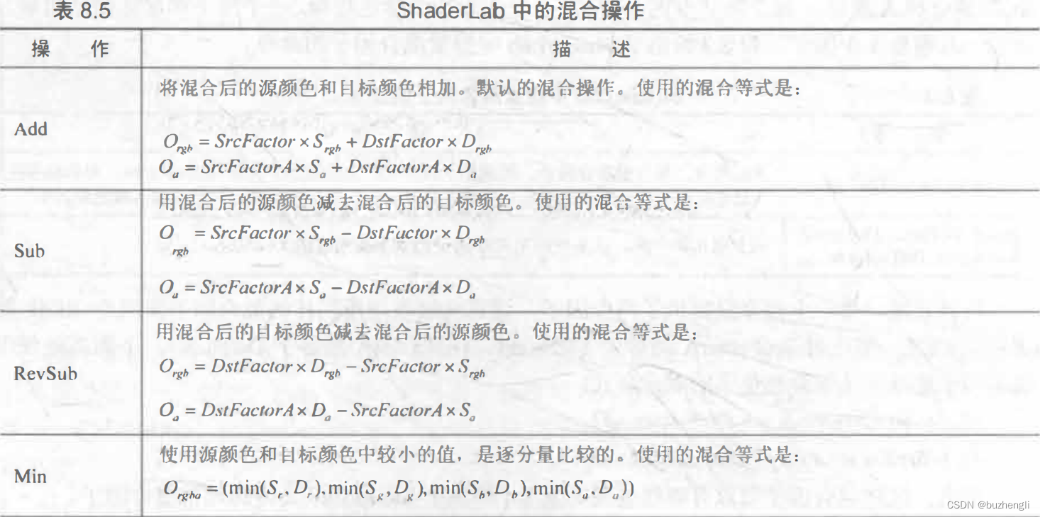
2. Mixing operation
The previous default blending formulas are all additions. Of course, we can also use some other blending operation commands (BlendOp Bl a>endOpera)noit

3. Common mixed types
Blend SrcAlpha OneMinusSrcAlpha   //正常(Normal),即透明度混合

Blend OneMinusDstColor One     //柔和相加(Soft Additive)

Blend DstColor Zero  //正片叠底(Multiply),即相乘

Blend DstColor SrcColor  //两倍相乘(2x Multiply)

BlendOp Min
Blend One One   //变暗(Darken)虽然使用了混合因子,但对结果没有任何影响,因为使用了Min

BlendOp Max
Blend One One    //变亮(Lighten)虽然使用了混合因子,但对结果没有任何影响,因为使用了Max

Blend OneMinusDstColor One      //滤色(Screen)等同于 Blend One OneMinusSrcColor

Blend One One  //线性减淡(Linear Dodge)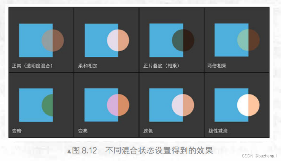
7. Transparency effect of double-sided rendering
1. Double-sided rendering for transparency test
It is basically the same as the transparency test code of the first three.2, with only one more line of code:
Pass {
    Tags { "LightMode" = "ForwardBase" }

    //使用了Cull语句,关闭了剔除功能,使该物体的所有渲染图元都会被渲染。
    Cull Off
The following is the difference between using double-sided rendering and not using double-sided rendering. We found that using double-sided rendering, the internal rendering results can be seen through the hollow area.
2. Double-sided rendering with transparency mixing
Because transparency blending turns off depth writing, we need to ensure that primitives are rendered from back to front. But if we directly turn off the culling function, we cannot guarantee the rendering order of an object.
For this reason, we divide the double-sided rendering work into two Passes - the first Pass only renders the back side, and the second Pass only renders the front side. Unity will execute each Pass in the SubShader, so we can ensure that the back side is always rendered on the front side. Render before rendering.
To implement it, it is actually to copy the Pass statement in the code in 4 and 2, and then use the Cull command in the two Passes to eliminate the rendering primitives in different directions:
Shader "MyShader/Chapter 8/Alpha Blend With Both Side" {
Properties {
_Color ("Color Tint", Color) = (1, 1, 1, 1)
_MainTex ("Main Tex", 2D) = "white" {}
_AlphaScale ("Alpha Scale", Range(0, 1)) = 1
}
SubShader {
Tags {"Queue"="Transparent" "IgnoreProjector"="True" "RenderType"="Transparent"}
Pass {
Tags { "LightMode"="ForwardBase" }
// 剔除正面,渲染背面
Cull Front
ZWrite Off
Blend SrcAlpha OneMinusSrcAlpha
CGPROGRAM
#pragma vertex vert
#pragma fragment frag
#include "Lighting.cginc"
fixed4 _Color;
sampler2D _MainTex;
float4 _MainTex_ST;
fixed _AlphaScale;
struct a2v {
float4 vertex : POSITION;
float3 normal : NORMAL;
float4 texcoord : TEXCOORD0;
};
struct v2f {
float4 pos : SV_POSITION;
float3 worldNormal : TEXCOORD0;
float3 worldPos : TEXCOORD1;
float2 uv : TEXCOORD2;
};
v2f vert(a2v v) {
v2f o;
o.pos = UnityObjectToClipPos(v.vertex);
o.worldNormal = UnityObjectToWorldNormal(v.normal);
o.worldPos = mul(unity_ObjectToWorld, v.vertex).xyz;
o.uv = TRANSFORM_TEX(v.texcoord, _MainTex);
return o;
}
fixed4 frag(v2f i) : SV_Target {
fixed3 worldNormal = normalize(i.worldNormal);
fixed3 worldLightDir = normalize(UnityWorldSpaceLightDir(i.worldPos));
fixed4 texColor = tex2D(_MainTex, i.uv);
fixed3 albedo = texColor.rgb * _Color.rgb;
fixed3 ambient = UNITY_LIGHTMODEL_AMBIENT.xyz * albedo;
fixed3 diffuse = _LightColor0.rgb * albedo * max(0, dot(worldNormal, worldLightDir));
return fixed4(ambient + diffuse, texColor.a * _AlphaScale);
}
ENDCG
}
Pass {
Tags { "LightMode"="ForwardBase" }
// 剔除背面,渲染正面
Cull Back
ZWrite Off
Blend SrcAlpha OneMinusSrcAlpha
CGPROGRAM
#pragma vertex vert
#pragma fragment frag
#include "Lighting.cginc"
fixed4 _Color;
sampler2D _MainTex;
float4 _MainTex_ST;
fixed _AlphaScale;
struct a2v {
float4 vertex : POSITION;
float3 normal : NORMAL;
float4 texcoord : TEXCOORD0;
};
struct v2f {
float4 pos : SV_POSITION;
float3 worldNormal : TEXCOORD0;
float3 worldPos : TEXCOORD1;
float2 uv : TEXCOORD2;
};
v2f vert(a2v v) {
v2f o;
o.pos = UnityObjectToClipPos(v.vertex);
o.worldNormal = UnityObjectToWorldNormal(v.normal);
o.worldPos = mul(unity_ObjectToWorld, v.vertex).xyz;
o.uv = TRANSFORM_TEX(v.texcoord, _MainTex);
return o;
}
fixed4 frag(v2f i) : SV_Target {
fixed3 worldNormal = normalize(i.worldNormal);
fixed3 worldLightDir = normalize(UnityWorldSpaceLightDir(i.worldPos));
fixed4 texColor = tex2D(_MainTex, i.uv);
fixed3 albedo = texColor.rgb * _Color.rgb;
fixed3 ambient = UNITY_LIGHTMODEL_AMBIENT.xyz * albedo;
fixed3 diffuse = _LightColor0.rgb * albedo * max(0, dot(worldNormal, worldLightDir));
return fixed4(ambient + diffuse, texColor.a * _AlphaScale);
}
ENDCG
}
}
FallBack "Transparent/VertexLit"
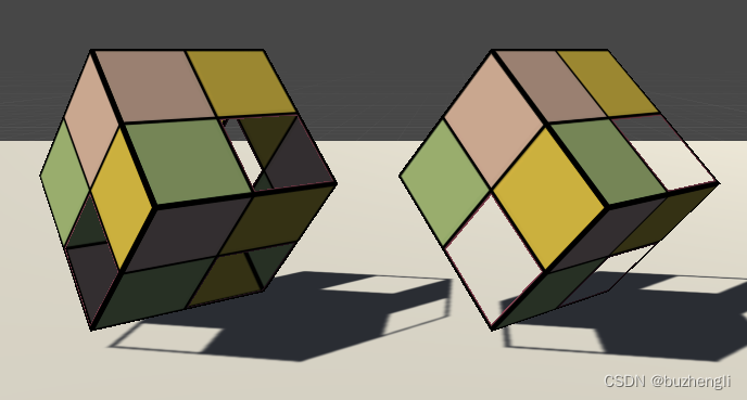
}
In the end we will get the following effect. Double-sided rendering is used on the left and not on the right.
