Reference tutorial:[13-1] PWR power control_bilibili_bilibili
1. PWR (Power Control) power control:
(1) PWR is responsible for managing the power supply part inside STM32 and can implement the functions of programmable voltage monitor and low power consumption mode.
(2) The programmable voltage monitor (PVD) can monitor the VDD power supply voltage. When VDD drops below the PVD threshold or rises above the PVD threshold, the PVD will trigger an interrupt to perform emergency shutdown tasks.
(3) Low power consumption modes include sleep mode (Sleep), stop mode (Stop) and standby mode (Standby), which can reduce the power of STM32 when the system is idle. consumption and extend the use time of the equipment.
2. Power supply block diagram:
(1) The VDDA power supply area is an analog power supply area (the A/D converter also has two pins VREF that provide reference voltages); the VDD power supply area and the 1.8V power supply area are digital power supply areas, and the CPU core, memory and built-in digital The peripherals belong to the 1.8V power supply area, and the 1.8V voltage is provided by the voltage regulator. The purpose of providing lower voltage is to reduce power consumption.
(2) There is a low voltage detector in front of the backup power supply area to control the switch of VBAT. When VDD is powered on, the backup power supply area is powered by VDD. When VDD is not powered on, the backup power supply area is powered by VBAT (if the RTC clock source selects LSE, when VDD When power is off, RTC and LSE are powered by VBAT, and RTC can still work normally).

3. Power-on reset and power-off reset:
When VDD or VDDA is too low, the internal circuit directly generates a reset signal (active at low level). There is a hysteresis voltage of 40mV between the limits of whether to generate a reset signal. When the voltage goes from low to high, it needs to be higher than the upper limit POR (Power On Reset). ) will release the reset. When the voltage goes from high to low, it needs to be lower than the lower limit PDR (Power Down Reset) to reset. This is to prevent the voltage from shaking near a certain threshold, causing the reset signal to shake.

4. Programmable voltage monitor:
The rising edge or falling edge of PVD output can trigger an interrupt (through external interrupt). In addition, unlike "power-on reset and power-down reset", the PVD threshold can be set through the program.

5. Low power consumption mode:

6. Mode selection:After executing the WFI (Wait For Interrupt) or WFE (Wait For Event) instruction, STM32 enters the low power consumption mode.

(1) Sleep mode:
①If SLEEPDEEP=0, after executing the WFI/WFE instruction, STM32 enters sleep mode, the program suspends running, and after waking up, the program continues running from where it was paused .
②The SLEEPONEXIT bit determines whether STM32 will enter sleep immediately after executing WFI or WFE, or wait until STM32 exits from the lowest priority interrupt handler.
③In sleep mode,all I/O pins maintain their status in running mode.
④The WFI instruction enters sleep mode and can be awakened by any interrupt responded by NVIC.
⑤WFE instruction enters sleep mode and can be awakened bywakeup event.
(2) Stop mode:
①If SLEEPDEEP=1, PDDS=0, after executing the WFI/WFE instruction, STM32 enters the stop mode, the program suspends running, and the program continues running from the paused place after waking up .
② If LPDS=0, the voltage regulator is turned on in shutdown mode; if LPDS=1, the voltage regulator is in a low power consumption state in shutdown mode (more power saving, but higher wake-up delay).
③All clocks in the 1.8V power supply area are stopped, PLL, HSI and HSE are disabled, and SRAM and register contents are retained .
④In shutdown mode,all I/O pins maintain their status in run mode.
⑤When an interrupt or wake-up event causes the shutdown mode to exit, HSI is selected as the system clock ( After waking up STM32, the system clock needs to be Select back to HSE to configure the main frequency to the original 72MHz).
⑥The WFI instruction enters the stop mode and can be awakened by any EXTI interrupt.
⑦The WFE instruction enters stop mode and can be awakened by any EXTI event.
(3) Standby mode:
①If SLEEPDEEP=1, PDDS=1, after executing the WFI/WFE instruction, STM32 enters standby mode, and the program starts from the beginning after waking up.
②The entire 1.8V power supply area is powered off, PLL, HSI and HSE are also powered off, SRAM and register contents are lost, and only backup registers and standby circuits maintain power supply< /span>.
③In standby mode, all I/O pins become high impedance (floating input).
④The rising edge of the WKUP pin, the rising edge of the RTC alarm event, the external reset on the NRST pin, and the IWDG reset. If one of the four conditions is met, the standby mode will be exited< /span>.
7. Modify the main frequency:
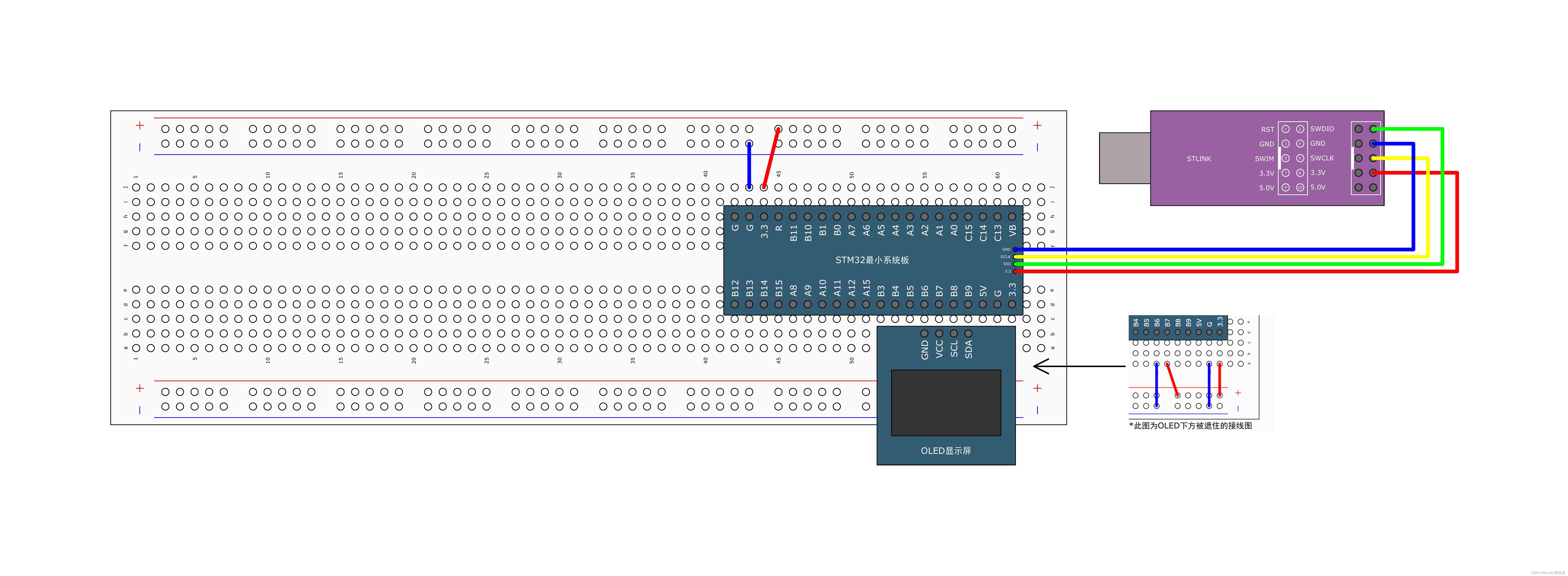
(1) Connect the circuit as shown in the figure below, and make a copy of the OLED display project folder to use as a template.

(2) The system_stm32f10x.h file and the system_stm32f10x.c file are used to configure the RCC clock tree. If you want to modify the system frequency, you can find the red file in the system_stm32f10x.c file. The location of the box. Currently, the blue box selected is the macro definition that configures the system main frequency to 72MHz. Comment out the macro definition and unblock one of the macro definitions in the orange box to modify the main frequency. (F103C8T6 is an MD, medium-capacity, non-value series. The two lines of code 107 and 108 in the picture will be removed during pre-compilation, so ignore them)

(3) Paste the following code in the main.c file, compile it, and download the program to the development board to observe the display of the OLED screen. (You need to change the system frequency, compile repeatedly, and compare the difference before and after changing the frequency)
#include "stm32f10x.h"                  // Device headerCmd
#include "OLED.h"
#include "Delay.h"

int main()
{
	OLED_Init();

	OLED_ShowString(1,1,"SYSCLK:");
	OLED_ShowNum(1,8,SystemCoreClock,8);  //显示当前主频

	while(1)
	{
		//闪烁显示
		OLED_ShowString(2,1,"Running");
		Delay_ms(500);  //500个时间单位
		OLED_ShowString(2,1,"       ");
		Delay_ms(500);  //500个时间单位
	}
}
8. Mode selection sleep mode:
(1) Connect the circuit as shown in the figure below, and copy the project folder of serial port sending + receiving to use as a template.

(2) Paste the following code in the main.c file, then compile it, download the program to the development board for debugging, and use the serial port assistant to send data to the microcontroller. Every time data is sent, the OLED screen flashes "Running".
#include "stm32f10x.h"                  // Device headerCmd
#include "OLED.h"
#include "Serial.h"
#include "Delay.h"

uint8_t RxData ;

int main()
{
	OLED_Init();
	Serial_Init();

	OLED_ShowString(1, 1, "RxData:");

	while(1)
	{
		if(Serial_GetRxFlag() == 1)  //判断是否有新数据到来
		{
			RxData = Serial_GetRxData();  //把接收的新数据拷贝到RxData中
			Serial_SendByte(RxData);      //把接收到的数据传给电脑
			//(调试时注意选择HEX模式进行发送和接收)
			OLED_ShowHexNum(1, 8, RxData, 2);
		}
		OLED_ShowString(2,1,"Running");
		Delay_ms(500);  //500个时间单位
		OLED_ShowString(2,1,"       ");
		Delay_ms(500);  //500个时间单位

		__WFI();   //进入睡眠模式(中断唤醒)
		//默认SLEEPDEEP=0(立刻睡眠)
	}
}
(3) Program explanation: After downloading the program to the development board, the program quickly comes to "__WFI();". At this time, STM32 enters sleep mode and the program stops running, If you use the serial port assistant to send data to STM32, an interrupt will be triggered and STM32 will wake up from sleep mode. First, the interrupt function of the serial port will be executed to complete the reception of data, and then the program will start from " __WFI();" The next step of the statement is to determine whether new data has arrived and start execution. In this example, 100% of new data has arrived, so the OLED screen will display the HEX format data just sent, and then "Running" will flash once. , the program comes to "__WFI();" and enters sleep mode again.
9. Mode selection: shutdown mode:
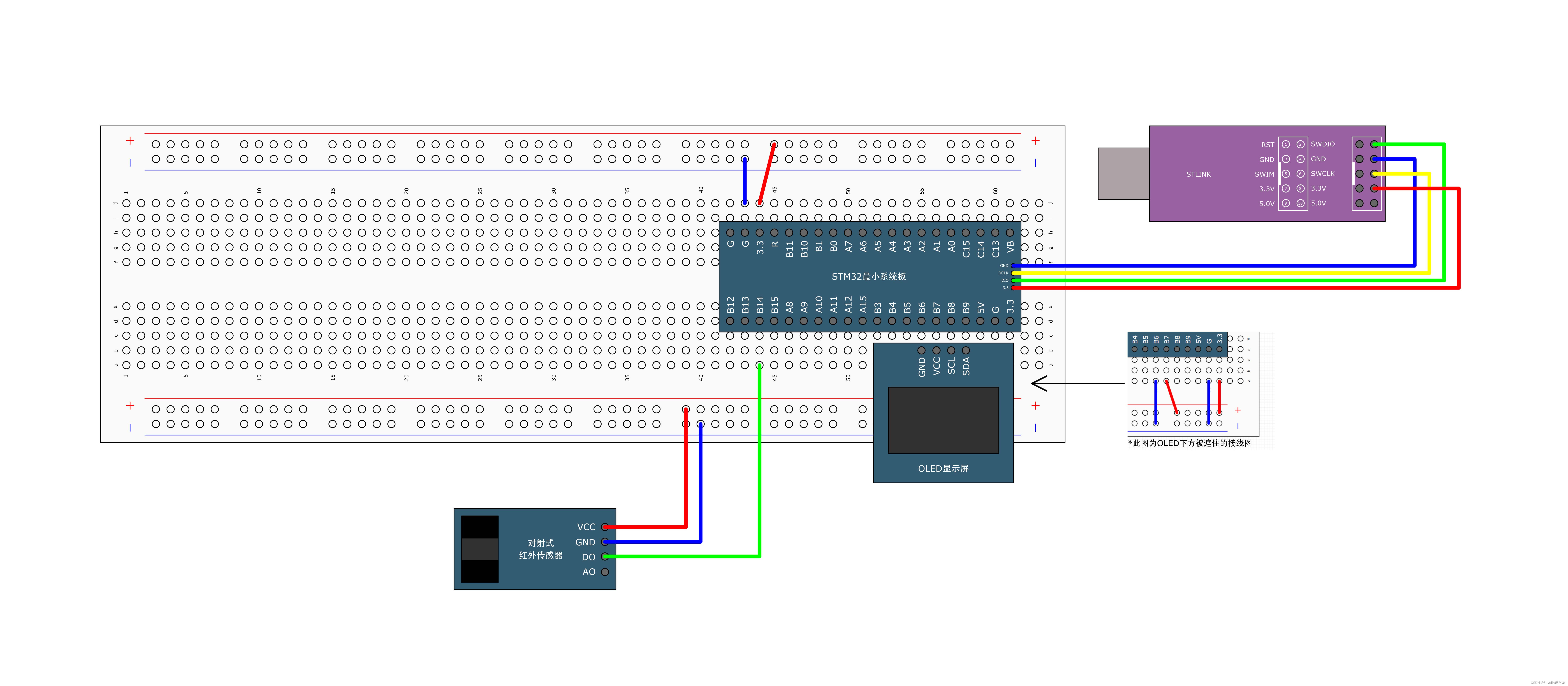
(1) Connect the circuit as shown in the figure below, and copy the through-beam infrared sensor project folder to use as a template.

(2) There are functions related to the PWR module in the stm32f10x_pwr.h file.
[1]PWR_DeInit function: restore default configuration.
[2]PWR_BackupAccessCmd function: Enables access to the backup area.
[3]PWR_PVDCmd function: Enable PVD output.
[4]PWR_PVDLevelConfig function: Configure the threshold voltage of PVD.
[5]PWR_WakeUpPinCmd function: Enable the WKUP pin located at PA0 (used in standby mode).
[6]PWR_EnterSTOPMode function: Put STM32 into stop mode.
[7]PWR_EnterSTANDBYMode function: Put STM32 into standby mode.
[8]PWR_GetFlagStatus function: Get the flag bit.
[9]PWR_ClearFlag function: clear the flag bit.

(3) Paste the following code in the main.c file, compile it, and download the program to the development board for debugging. (Each time the light is blocked, an external interrupt will be generated. STM32 will wake up from the shutdown mode. >, after processing the interrupt, the program starts executing from the "SystemInit();" statement)
#include "stm32f10x.h"                  // Device headerCmd
#include "OLED.h"
#include "CountSensor.h"
#include "Delay.h"

int main()
{
	OLED_Init();
	CountSensor_Init();

	RCC_APB1PeriphClockCmd(RCC_APB1Periph_PWR, ENABLE);  //开启PWR的时钟

	OLED_ShowString(1,3,"Count:");

	while(1)
	{
		OLED_ShowNum(2,3,CountSensor_Get(),3);  //显示挡光次数

		OLED_ShowString(3,1,"Running");
		Delay_ms(500);  //500个时间单位
		OLED_ShowString(3,1,"       ");

		PWR_EnterSTOPMode(PWR_Regulator_ON, PWR_STOPEntry_WFI);  //进入停机模式
		//PWR_Regulator_ON:电压调节器开启
		//PWR_STOPEntry_WFI:可被任意一个EXTI中断唤醒

		//唤醒STM32后需要将系统时钟选择回HSE
		SystemInit();
	}
}
10. Mode selection standby mode:
(1) Connect the circuit as shown in the figure below, and copy the real-time clock project folder to use as a template.

(2) Paste the following code in the main.c file, compile it, and download the program to the development board for debugging.
①The alarm event will occur 10 seconds after the program download is completed. At this time, STM32 is awakened from standby mode, due to RTC The program has already been initialized once when it has just been downloaded, so it will not be initialized again and the timing will not be reset, butthe alarm will be reset to 10 seconds after the current timestamp< /span> . STM32 will be awakened every 10 seconds, and then enter standby mode again, and so on, that is to say
②Use a wire to provide a rising edge to PA0. The rising edge of the WKUP pin can cause STM32 to exit standby mode. This has nothing to do with the alarm event. , but the alarm will still be reset to 10 seconds after the current timestamp, and then enter standby mode again.
#include "stm32f10x.h"                  // Device headerCmd
#include "OLED.h"
#include "MyRTC.h"
#include "Delay.h"

int main()
{
	OLED_Init();
	MyRTC_Init();

	RCC_APB1PeriphClockCmd(RCC_APB1Periph_PWR, ENABLE);  //开启PWR的时钟

	OLED_ShowString(1, 1, "CNT:");
	OLED_ShowString(2, 1, "ALR:");
	OLED_ShowString(3, 1, "ALRF:");

	PWR_WakeUpPinCmd(ENABLE);  //使能位于PA0位置的WKUP引脚(本例需要WKUP引脚产生上升沿)

	//闹钟定时在当前时间戳后10秒
	uint32_t Alarm = RTC_GetCounter() + 10;
	RTC_SetAlarm(Alarm);

	while(1)
	{
		OLED_ShowNum(1,6,RTC_GetCounter(),10);
		OLED_ShowNum(2,6,Alarm,10);
		OLED_ShowNum(3,6,RTC_GetFlagStatus(RTC_FLAG_ALR),1);  //闹钟标志位:闹钟响时该位置1

		OLED_ShowString(4,1,"Running");
		Delay_ms(500);  //500个时间单位
		OLED_ShowString(4,1,"       ");
		Delay_ms(500);  //500个时间单位

		OLED_ShowString(4,9,"STANDBY");
		Delay_ms(1000);  //500个时间单位
		OLED_ShowString(4,9,"       ");
		Delay_ms(100);  //500个时间单位

		OLED_Clear();  //清屏

		PWR_EnterSTANDBYMode();   //进入待机模式
		//(本例中闹钟事件上升沿/WKUP引脚的上升沿可以退出待机模式,程序从头开始执行)
	}
}