Introduction
github
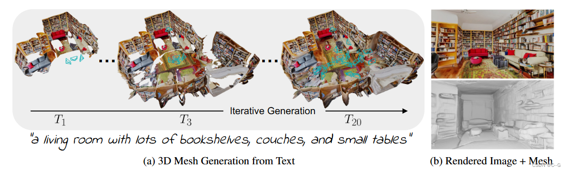
Utilizes a pre-trained 2D text-to-image model to synthesize a sequence of images from different poses. To promote these outputs into a consistent 3D scene representation, combining monocular depth estimation with text-conditioned drawing models, we propose a sequential alignment strategy that iteratively fuses scene frames with existing geometry to create a Seamless Grid
Implementation process
Iterative 3D Scene Generation
Generate scene representation mesh over time M = ( V , C , S ) M=(V,C,S) M=(V,C,S), V——vertex, C——vertex color, S——face set, input text prompts { P t } t = 1 T \{P_t\}^T_{t=1} {
Pt}t=1T, partner position { E t } t = 1 T \{ E_t \}^T_{t=1} {
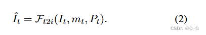
Et}t=1T, following the render-refine-repeat pattern, for each step of generation t, first render the current scene from a new viewpoint
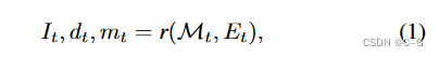
r is the classic rasterization function without shadows , I t I_t It\ is the rendered image, d t d_t dt is the depth of rendering, M t M_t MtImage space mask marks pixels with no observed content
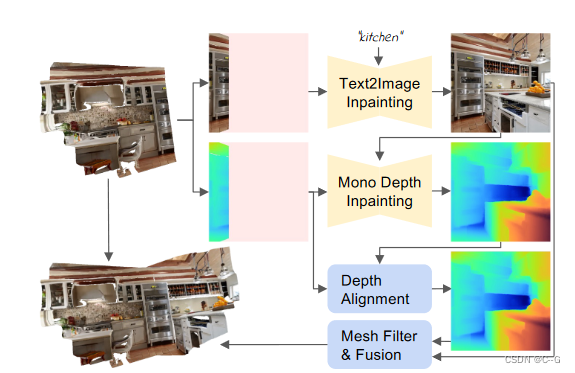
Using text-to-image model
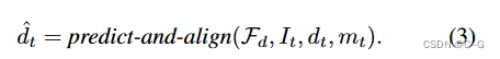
Apply monocular depth estimator in depth alignment F d F_d Fd b to draw unobserved depth
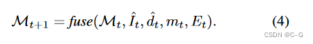
Utilize the fusion scheme to combine new content { I ^ t , d ^ t , m t } \{ \hat{I}_t,\hat{d}_t,m_t \} {
I^t,d^t,mt} Combine with existing grid
Depth Alignment Step
To properly combine old and new content, it is necessary to keep the old and new content consistent. In other words, similar areas in the scene, such as walls or furniture, should be placed at similar depths
Directly using predicted depth for backprojection results in hard cuts and discontinuities in the 3D geometry because depth scales are inconsistent between subsequent viewpoints
Apply a two-stage depth alignment method, using a pre-trained deep network (Irondepth: Iterative refinement of single-view depth using surface normal and its uncertainty), taking the true depth d of the known part of the image as input, And align the prediction results with it d ^ p = F d ( I , d ) \hat{d}_p=F_d(I,d) d^p=Fd(I,d)
(Infinite nature: Perpetual view generation of natural scenes from a single image) Optimize scale and displacement parameters, aligning differences in prediction and rendering in a least squares sense to improve results
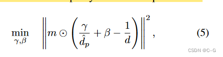
Mask out unobserved pixels by m and extract the alignment depth d ^ = ( y d ^ p + β ) − 1 \hat{d}=(\frac{y}{\hat{ d}_p}+\beta)^{-1} d^=(d^py+β)−1, apply a 5 × 5 Gaussian kernel to the mask edge to smooth d ^ \ hat{d} d^
Mesh Fusion Step
Insert new content in each iteration { I ^ t , d ^ t , m t } \{ \hat{I}_t,\hat{d}_t, m_t \} {
I^t,d^t,mt} into the scene, back-projecting the image space pixels into the world space point cloud
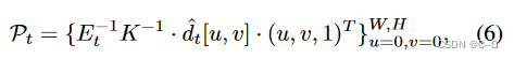
K ∈ R 3 x 3 K \in R^{3 x 3} K∈R3x3 is the camera pose parameter, W and H are the image width and height. Using simple triangulation, form each four adjacent pixels {(u, v), (u+1, v), (u, v+1), (u+1, v+1)} in the image Two triangles.
The estimated depth is noisy and this simple triangulation produces stretched 3D geometry.
Use two filters to remove extruded faces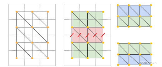
First, filter the faces based on their side lengths. If the Euclidean distance of any face edge is greater than the threshold δ edge, the face is deleted. Secondly, filter the faces according to the angle between the surface normal and the viewing direction
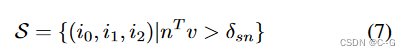
S is a set of faces, i 0 , i 1 , i 2 i_0, i_1,i_2 i0,i1,i2 is the vertex index of the triangle, δ s n \delta_{sn} dsn为阈值, m ∈ R 3 m \in R^3 m∈R3 是归一化法线, v ∈ R 3 v \in R^3 in∈R3 is the normalized view direction from the camera center to the starting average pixel position of the triangle in world space. This is to avoid drawing the relatively small number of pixels in the image into the network. Create textures over large areas of the grid
Finally fuse the newly generated mesh patch with the existing geometry, all back-projected from the pixels to the draw mask m t m_t mtThe faces in are stitched together with adjacent faces. These faces are already part of the mesh. In m t m_t mtContinue the triangulation scheme on all edges of but use m t m_t mtexisting vertex positions to create corresponding faces
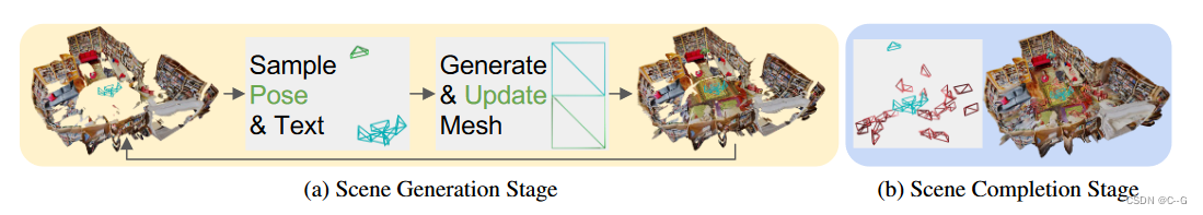
Two-Stage Viewpoint Selection
A two-stage viewpoint selection strategy that samples each next camera pose from the optimal position and subsequently refines the empty region
Generation Stage
Generation works best if each trajectory starts from a viewpoint with a mostly unobserved area. This generates the outline of the next block while still connecting to the rest of the scene
Change the camera position T 0 ∈ R 3 T_0∈R^3 T0∈R3 Follow direction L ∈ R 3 L∈R^3 L∈R3 Perform uniform translation: T i + 1 = T i − 0.3 L T_{i+1}=T_i−0.3L Ti+1=Ti−0.3L, if the average rendering depth is greater than 0.1, stop, or discard the camera after 10 steps, this avoids the view being too close Existing geometry
Create a closed room layout by selecting a trajectory that generates the next block in a circular motion, roughly centered on the origin. found that by designing the text prompts accordingly, the text-to-image generator could be prevented from generating furniture in unwanted areas. For example, for gestures looking at the floor or ceiling, we selected text cues containing only the words "floor" or "ceiling," respectively.
Completion Stage
Since the scene is generated in real time, the mesh contains holes that are not observed by any camera, and the scene is completed by sampling additional pose posteriors
Voxelize the scene into dense uniform cells, randomly sample within each cell, discard those that are too close to existing geometry, choose a pose for each cell to see most unobserved pixels, based on all Draw the scene with the selected camera pose
Cleaning the draw mask is important because the text-to-image generator produces better results for large connected areas
First, use a classic rendering algorithm to draw small holes, expand the remaining holes, remove all faces that fall in the expanded area and are close to the rendering depth, and perform Poisson surface reconstruction on the scene mesh. This will close any remaining wellbore after completion and smooth out discontinuities. The result is a watertight mesh of the generated scene, which can be rendered with classic rasterization
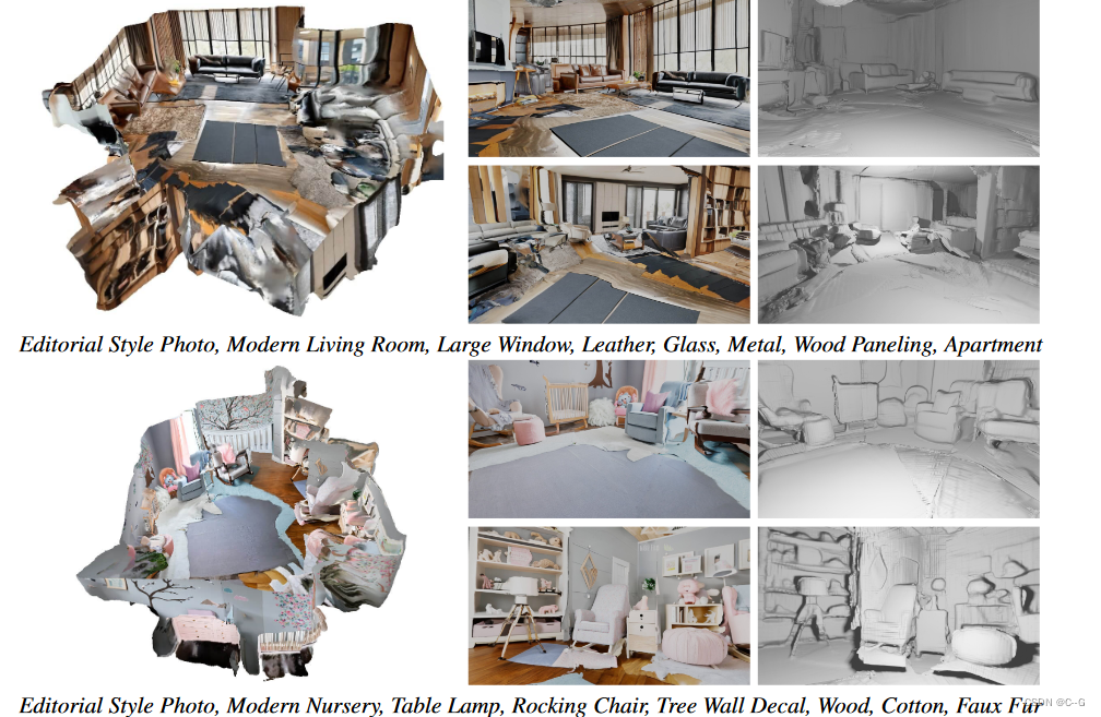
Result

Limitations
The method allows the generation of 3D room geometries from arbitrary text prompts that are highly detailed and contain consistent geometries. However, methods may still fail under certain conditions. First, the thresholding scheme may not detect all stretched regions, which may result in residual distortion. Additionally, some holes may not have been fully completed after the second stage, which resulted in oversmoothed areas after applying Poisson reconstruction. The scene representation does not break down the material in the light, the light is baked in shadows or bright lights, which is produced by the diffusion model.