There is a big difference between STM32 MCU and 51 MCU. Not only is there a big difference in structure, STM32 is more complicated. In terms of operation, STM32 is also much more complicated. Handwritten code on 51 MCU can directly operate pins, but STM32 MCU Before operating the pins, a lot of initialization work is required, such as enabling the clock and initializing the GPIO pins.
The following is a brief introduction to the development of STM32 single-chip microcomputer. This article is a simulation. It does not need a real STM32 single-chip microcomputer. It only needs to install and develop related software on the computer, mainly keil-mdk and proteus.
The keil installed here is a version that supports STM32 single-chip microcomputers. This requires the installation of the version of mdk. Here is a keil download link that supports mdk , extraction code: 1234. Its installation and cracking are similar to keil-51. The cracking also uses keygen.exe to generate the registration code. After installation, you also need to install the package that supports STM32 microcontrollers: Keil.STM32F1xx_DFP.1.0.5.pack, download the package from the link above You can install it offline, as follows:
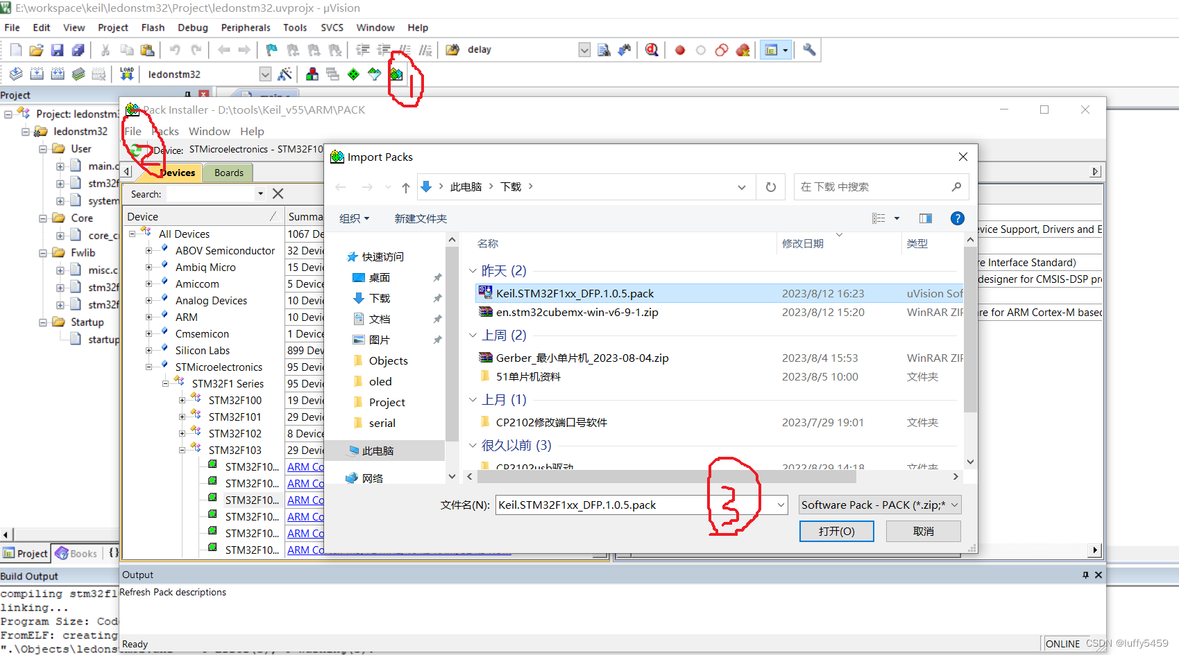
Select the Pack Install button on the keil toolbar, select File->Import in the pop-up box, and the file selection dialog box will pop up, select the downloaded pack package, and you can install it offline.
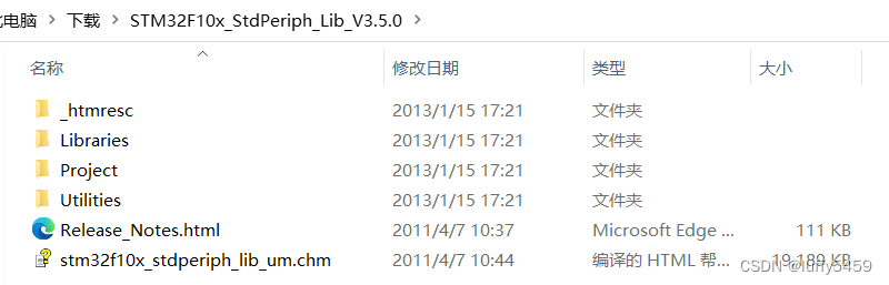
We need a standard library to construct the STM32 project. Similarly, the download link just now comes with: STM32F10x_StdPeriph_Lib_V3.5.0.rar. After decompression, the structure is as follows:
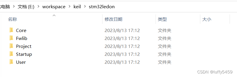
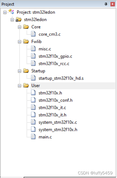
Here we use the standard library to build the STM32 project, which contains the header files and source files required by our project, as well as the startup file. Before we create a new STM project, prepare a project file structure like this:
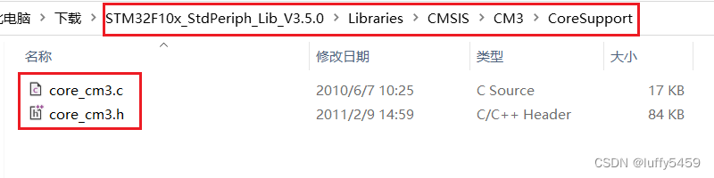
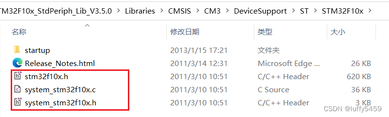
Core here can also be named CMSIS. According to personal habits, it literally means the core file. Here we need to copy the core_cm3.h and core_cm3.c files in the standard library. The path is STM32F10x_StdPeriph_Lib_V3.5.0\Libraries\CMSIS\CM3\CoreSupport
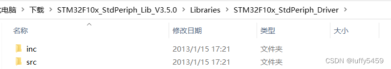
Fwlib is the meaning of firmware library. Here we copy the inc and src folders of STM32F10x_StdPeriph_Lib_V3.5.0\Libraries\STM32F10x_StdPeriph_Driver\src in the standard library.
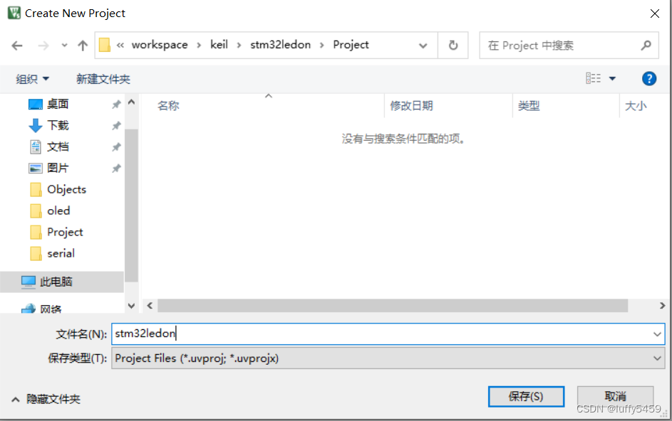
Project is used to store keil projects, and later create new projects in keil, we specify the save location here.
User, here is the user file, copy the stm32f10x.h, system_stm32f10x.c, system_stm32f10x.h files and
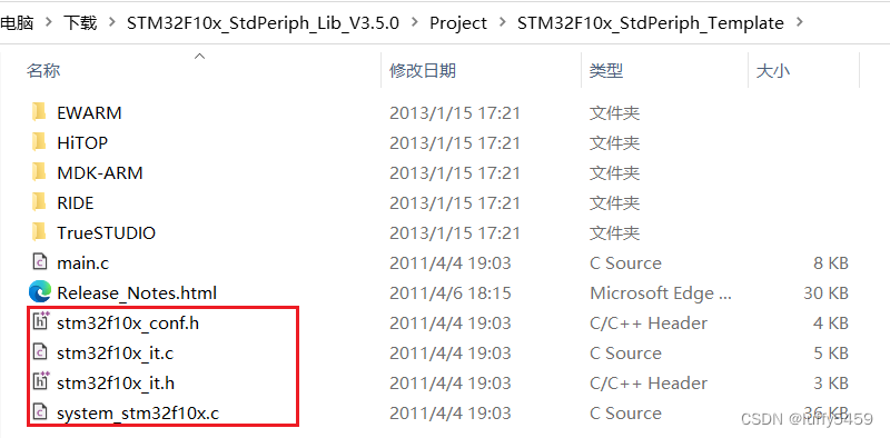
stm32f10x_conf.h, stm32f10x_it.c, stm32f10x_it.h, system_stm32f10x.h under STM32F10x_StdPeriph_Lib_V3.5.0\Project\STM32F10x_StdPeriph_Template (repeated).
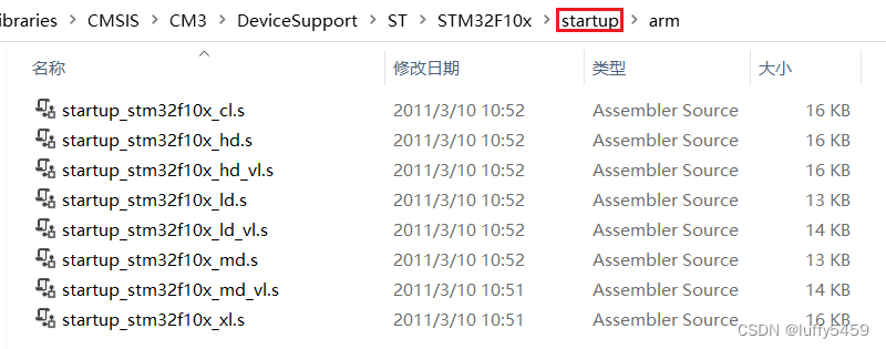
The folder where the Startup startup file is stored, here we copy all the files ending in s under STM32F10x_StdPeriph_Lib_V3.5.0\Libraries\CMSIS\CM3\DeviceSupport\ST\STM32F10x\startup\arm (actually only one is used).
In this way, we have files in the other four directories except that there are no files in the Project folder.
keil new construction
Open keil-mdk, create a new project, and select the Project folder just prepared for the location.
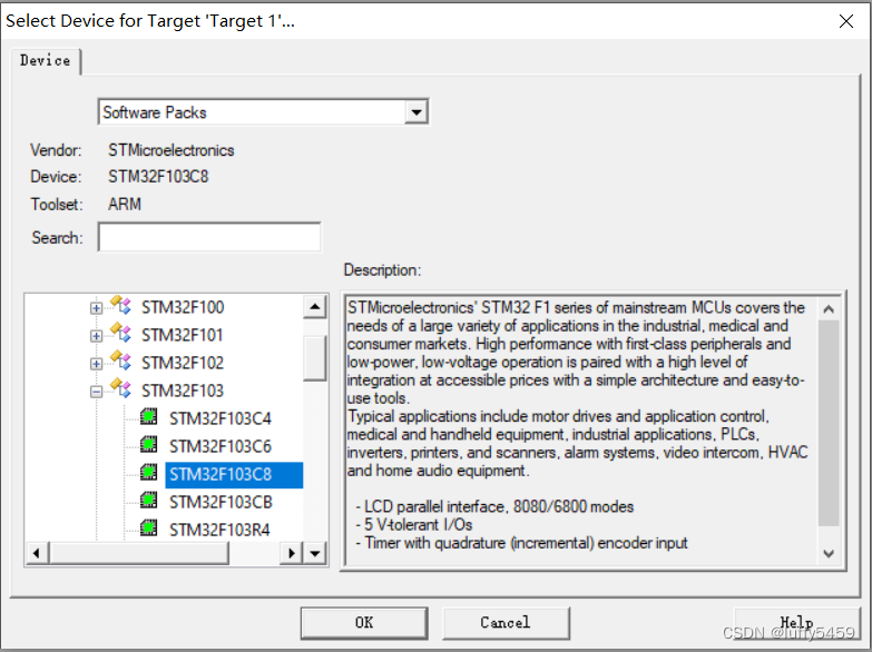
In the next wizard, select the device for the build target. We choose STM32F103C8, and others are also available, depending on the simulation needs.
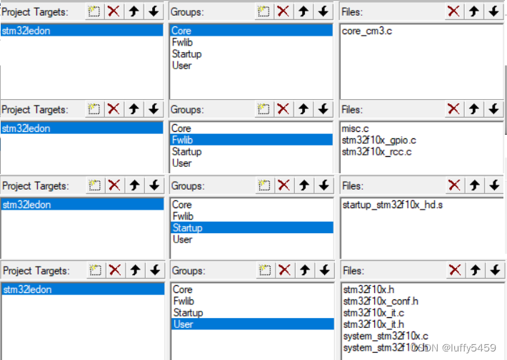
This new project has no content, we need to reset it. Click the "Manage Engineering Items" button (three colored blocks) on the toolbar:
Project Targets is changed to the project name,
Groups Add four groups here, namely Core, Fwlib, Startup, User, and the files in them. We select the files in the folders Core, Fwlib, Startup, and User before, and the structure is as follows:
We also need to manually add the main.c file in the User directory, and then right-click on the User Group to select: Add existing files to the group.
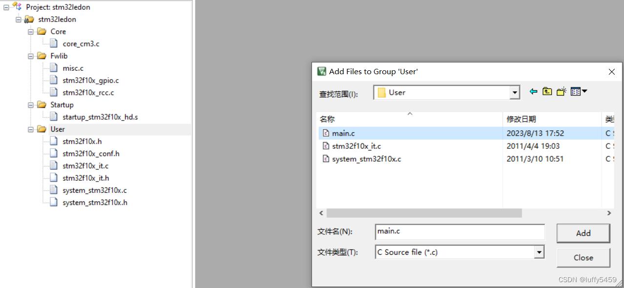
The final project file structure:
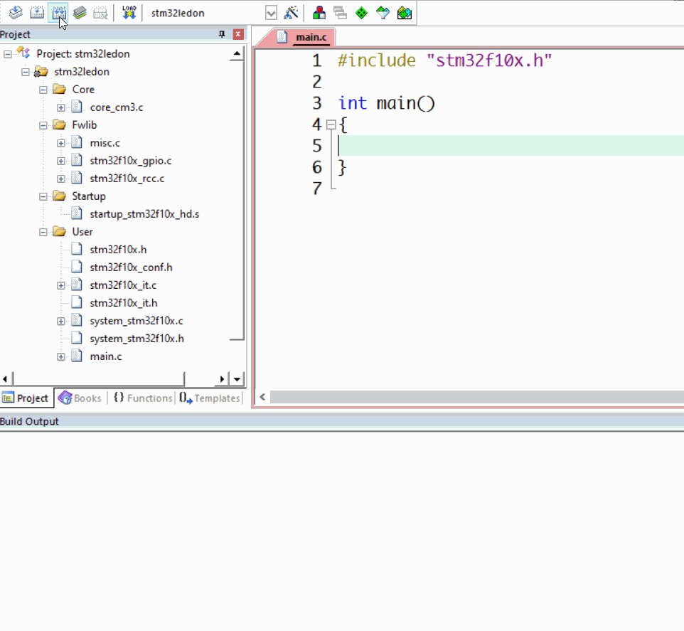
We can add some code to main.c so that it can be compiled as an empty project.
#include "stm32f10x.h"
int main()
{
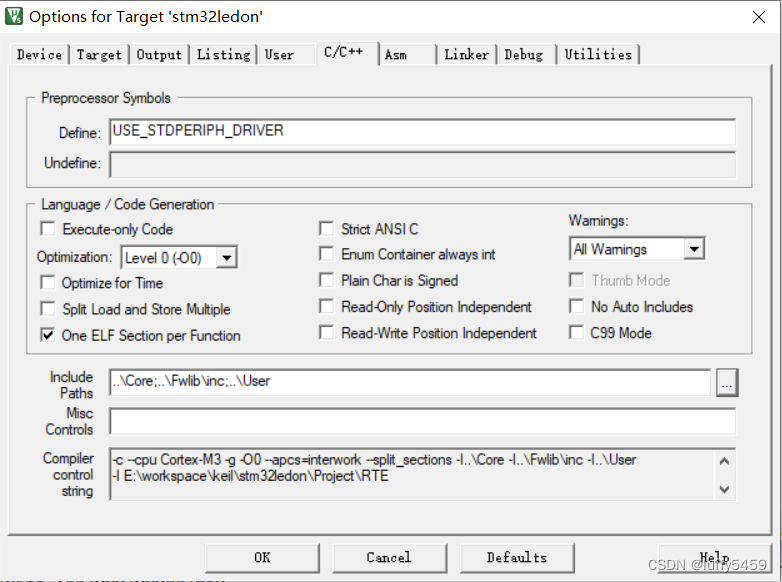
}At this time, an error will be reported when compiling the project directly. We need to make settings to set the header file search range. The specific operation is to click the magic wand (Options for Targets) on the toolbar, select c/c++ in the pop-up box, enter USE_STDPERIPH_DRIVER in Define, and Include Paths below Select our folder Core, Fwlib/inc, User three directories, manually select:
Finally, it can be compiled successfully:
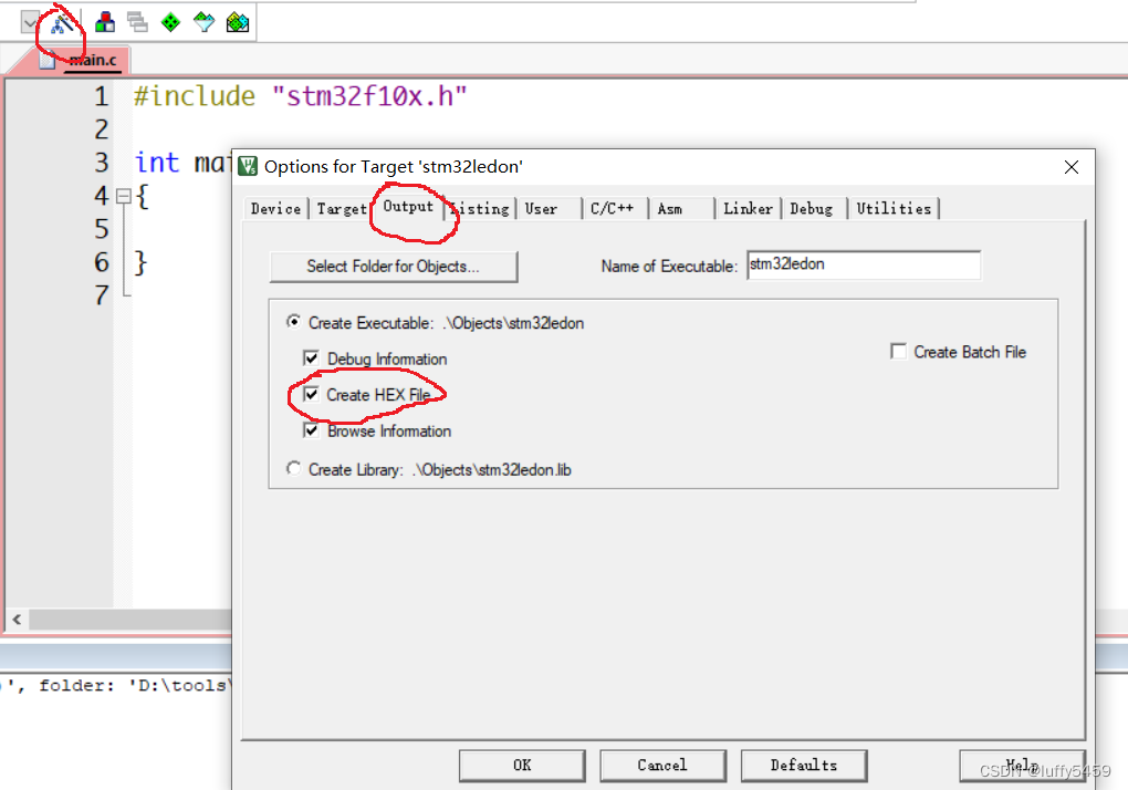
Because the simulation needs a hex file at the end, it also needs a setting, click Options for Targets, switch to output, and then check Create HEX File:
The code for STM32 microcontroller lighting is somewhat complicated, mainly need to turn on the clock and set the pin level.
#include "stm32f10x.h"

void Delay()
{
	unsigned int i, j;
    for(i = 0; i < 2000; i++)
	  for(j = 0; j < 110; j++);
}

void LED_Config()
{
      GPIO_InitTypeDef GPIO_InitStructure;                  // GPIO初始化结构体

	  RCC_APB2PeriphClockCmd(RCC_APB2Periph_GPIOB, ENABLE); //APB2时钟使能,这里单片机开启的是B口,所以对应RCC_APB2Periph_GPIOB,如果开启A口,这里对应RCC_APB2Periph_GPIOA
	  GPIO_InitStructure.GPIO_Mode = GPIO_Mode_Out_PP;      // 推挽模式
	  GPIO_InitStructure.GPIO_Pin = GPIO_Pin_5;             // 管脚B5作为输出
	  GPIO_InitStructure.GPIO_Speed = GPIO_Speed_50MHz;     //时钟频率
      GPIO_Init(GPIOB, &GPIO_InitStructure);                // GPIO初始化,开启GPIOB,如果要开启A或者C,改变这里的GPIOA或者GPIOC
}

int main()
{
    LED_Config();
	  while(1)
	  {
			GPIO_SetBits(GPIOB, GPIO_Pin_5);
			Delay();
			GPIO_ResetBits(GPIOB, GPIO_Pin_5);
			Delay();
	 }
}
If the compilation does not report an error, you can start the simulation. In proteus, we build the led design diagram as shown below:
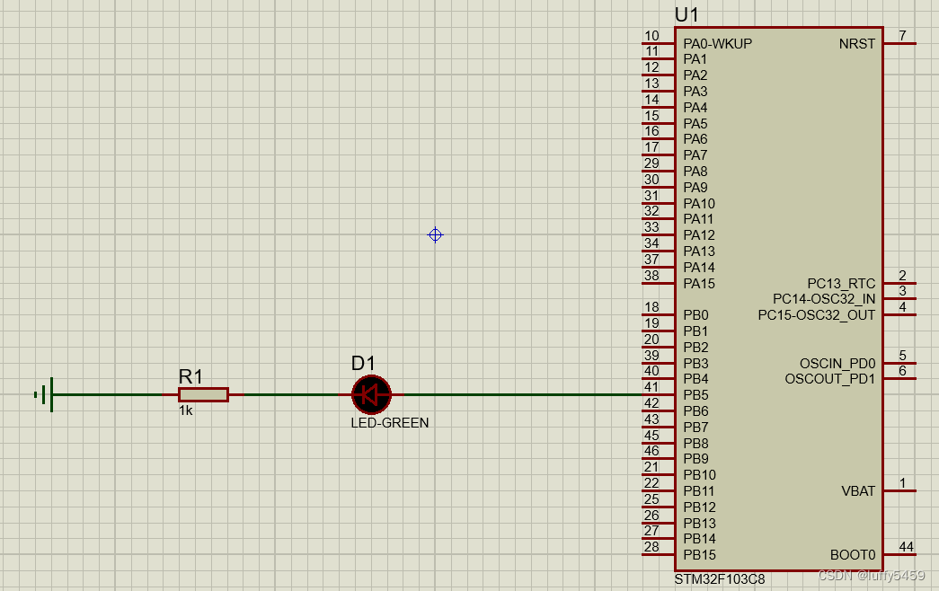
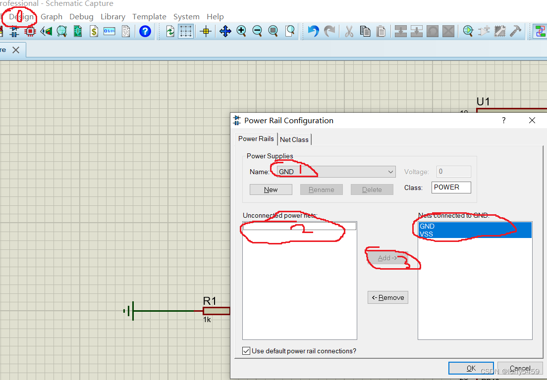
Select the chip STM32F103C8, then find the light-emitting diode LED-GREEN, add a resistor, and ground. Simple connection, the STM32 MCU seems to be a little different from the 51 MCU, here you need to deal with the connection, select Power Rail Configuration in the menu bar Design, and pass the parts listed on the left of GND and VCC/VDD through the Add in the middle The (move right) arrow is added to the right:
There is another important place that needs to be set, which is the crystal oscillator frequency of the microcontroller. If it is not set, an error will be reported:
Access to register of unclocked peripheral at 0x40010C00 cause BUS_FAULT [U1_CM3CORE]
This problem may only be reported during simulation. Some places say that the clock enable needs to be set in the code, but our code is obviously set, which is RCC_APB2PeriphClockCmd(RCC_APB2Periph_GPIOB, ENABLE); this code. This problem is very troublesome. At first I thought that the code did not execute the content in the main.c file. In fact, it is not, but the frequency of the crystal oscillator, but the frequency is also not set. I use the code generated by STM32CubeMX to execute without problem. Also very strange.

The 50MHz here is the clock frequency GPIO_Speed_50MHz set in the code.
Finally, the simulation does not report an error: 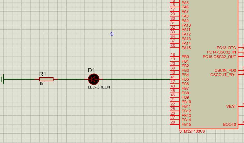
Here is to use the standard library to build the STM32 project, so some header files and source files of the standard library are added. Here, according to the characteristics of the project, the Core, Fwlib, Project, Startup, User folders are newly created, and related files are added, and finally in the keil project The groups Core, Fwlib, Startup, and User established in the target do not have the same meaning, but the names are the same. Finally, you need to manually add files to these groups.