Table of contents
1. GPIO register parameter value and meaning
2. Read and write register address
3. Hysteresis caused by Schmitt trigger
4. Definition and configuration of Qualcomm device tree pinctrl
5. Definition of msmxxxx-pinctrl.dtsi structure of Qualcomm device tree GPIO
This article mainly introduces the gpio configuration based on Qualcomm. The least common one is that the voltage offset caused by the hysteresis effect of gpio configuration has a certain impact on actual use. In the past embedded chips, only pull-up, pull-down, floating, However, in the Qualcomm chip, due to the management of the Qualcomm chip, the built-in Schmidt circuit is added to the pin to cause a certain hysteresis effect on the gpio, but it is not very clear in the Qualcomm code configuration document, and it is written It's very vague, and it doesn't work after trying. Finally, in the initialization of gpio, according to Qualcomm's register instructions, the configuration of gpio registers will take effect!
| author | daisy.skye's blog_CSDN blog-embedded, Qt, Linux field blogger |
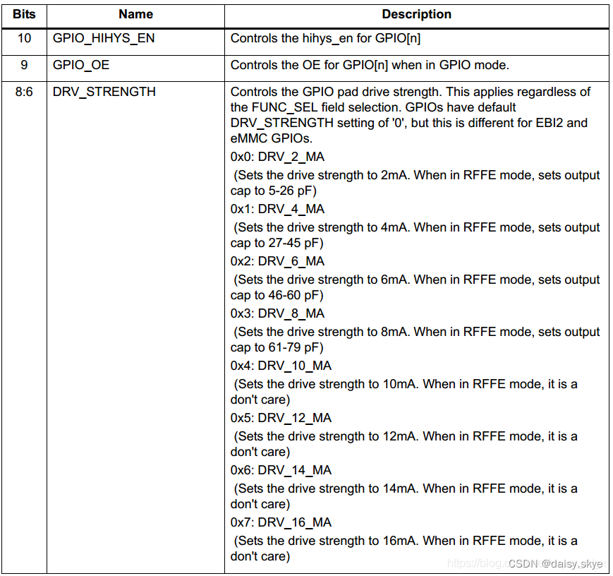
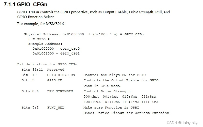
1. GPIO register parameter value and meaning
| Register parameter value |
|
| GPIO register address |
|

2. Read and write register address
| read register address |
For example, read gpio141, where 141 is a decimal representation, converted to hexadecimal is 0x8D
/system/bin # ./r 0x0108D000 0108d000: 00000001 The return value is 0x0000001 where 1 is the parameter value of the 0th bit, which means 0x1 is Pull Down Then read the definition of the gpio141 kernel /system/bin # cat /sys/kernel/debug/gpio | grep 141 GPIOs 0-141, platform/1000000.pinctrl, 1000000.pinctrl: gpio141 : in 0 2mA pull down If changed to no pull, you will need to change the register value to 0x00000000 ./r 【Register Address】【Register Value】 /system/bin # ./r 0x0108D000 0x000000000 0108d000: 00000000 /system/bin # cat /sys/kernel/debug/gpio | grep 141 GPIOs 0-141, platform/1000000.pinctrl, 1000000.pinctrl: gpio141 : in 0 2mA no pull |

3. Hysteresis caused by Schmitt trigger
In the above configuration, the description of the parameter GPIO_HIHYS_EN for the 10th bit is relatively small, which actually affects the hysteresis response of gpio, with a voltage difference of approximately 100~300mv
| Schmidt |
A Schmitt trigger is a circuit with positive feedback that converts an input signal into a stable output signal. When the amplitude of the input signal exceeds a certain threshold, the Schmitt trigger will generate an output signal and keep it in the high state. A Schmitt trigger switches the output signal back to a low state when the amplitude of the input signal falls below another threshold. The role of the Schmitt trigger is to eliminate noise and jitter in the input signal and generate a stable output signal. Because the Schmitt trigger has positive feedback, it can produce a well-defined output signal with small changes in the amplitude of the input signal. This makes Schmitt triggers well suited for signal processing and timing control in digital circuits. Schmitt triggers can also be used to eliminate switch bounce and eliminate transient noise. In an off circuit, when the switch is turned on or off, there is a bounce phenomenon, which can lead to erroneous signal transmission. By using a Schmitt trigger, this bounce phenomenon can be eliminated and correct signal transmission can be ensured. In summary, a Schmitt trigger is a very useful circuit that converts an input signal into a stable output signal and removes noise and jitter. It is widely used in digital circuits, especially in signal processing and timing control. |
| lag effect |
This hysteretic response is caused by the positive feedback mechanism of the Schmitt trigger. When a signal is in a high state, it affects the input signal through a feedback loop. This makes it necessary for the amplitude of the input signal to drop below the falling threshold to some extent before the output signal switches back to the low state. Therefore, the Schmitt trigger has a certain hysteresis effect. The hysteretic response makes the Schmitt trigger more stable and removes noise and jitter from the input signal. However, in some applications, the hysteresis response may cause unnecessary delays or errors. Therefore, when designing the circuit, it is necessary to carefully consider the hysteresis response of the Schmitt trigger and select the appropriate threshold and feedback circuit to meet the specific application requirements. |
4. Definition and configuration of Qualcomm device tree pinctrl
| pin definition |
Optional Properties (for standard pins): - function: String. Specifies the pin mux selection. Values must be one of: "alt1", "alt2", "alt3", "alt4" - input-schmitt-enable: No arguments. Enable schmitt-trigger mode. - input-schmitt-disable: No arguments. Disable schmitt-trigger mode. - bias-pull-up: No arguments. Pull up on pin. - bias-pull-down: No arguments. Pull down on pin. - bias-disable: No arguments. Disable pin bias. - slew-rate: Integer. Meaning depends on configured pin mux: *_SCL or *_SDA: 0: Standard(100kbps)& Fast(400kbps) mode 1: Highspeed (3.4Mbps) mode IC_DM or IC_DP: 0: normal slew rate 1: fast slew rate Otherwise: 0: fast slew rate 1: normal slew rate - input-enable: No arguments. Enable input (does not affect output.) - input-disable: No arguments. Disable input (does not affect output.) - drive-strength: Integer. Drive strength in mA. Valid values are 2, 4, 6, 8, 10, 12, 14, 16 mA. |