
The reference to 37 sensors and modules has been widely circulated on the Internet. In fact, there must be more than 37 sensor modules compatible with Arduino. In view of the fact that I have accumulated some sensors and modules on hand, according to the concept of practice (hands-on try), for the purpose of learning and communication, I am going to do experiments one by one here, and will record them regardless of whether they are successful or not. It is a difficult problem, and I hope to be able to throw bricks and spark jade.
[Arduino] 168 kinds of sensor module series experiment (data + code + graphics + simulation)
Experiment 43: 5V low level trigger single relay module (single module normally closed and normally open type)


Single-channel 5V relay module
1. General-purpose single-channel 5V relay module
1. Module features
(1) Comply with international safety standards, and there is an isolation slot between the control area and the load area;
(2) Double-sided FR-4 circuit board design, high-end stickers (3) It has power supply and relay action indication, it
is bright when it is closed, and it is not bright when it is disconnected; (
4) It is divided into two specifications: low-level trigger and high-level trigger;
(5) The relay can directly control various Equipment and load;
(6) Control DC or AC signal, can control 220V AC load;
(7) There is a normally open and a normally closed contact;
(8) The signal input terminal has a low level (or high level) signal
(9) It is more convenient to connect the blue KF301 terminal to the control line; (
10) Module size: 43 17 18.5MM, net weight: 15g.

Several experiments of single-channel 5V relay module
1. Experimental environment of single-channel 5V relay module
1. Hardware list required for the experiment——
Arduino Uno development board X1
DuPont lines (10 pieces are prepared)
LED light-emitting diode (blue) X1
220 ohms Current-limiting resistor (1/8W) x1
low-level trigger single-channel 5V relay module X1
high-level trigger single-channel 5V relay module X1
Proto Shield prototype expansion board (with mini breadboard) X1
key switch module (pull-down resistor and pull-up Resistor each 1) X2

2. The software platform required for the experiment -
code programming Arduino IDE (version 1.8.13),
simulation programming Linkboy (version V4.2),
graphics programming Mind+ (version V1.7.0 RC1.0) and learning while programming (online platform)
3. Experimental wiring diagram——

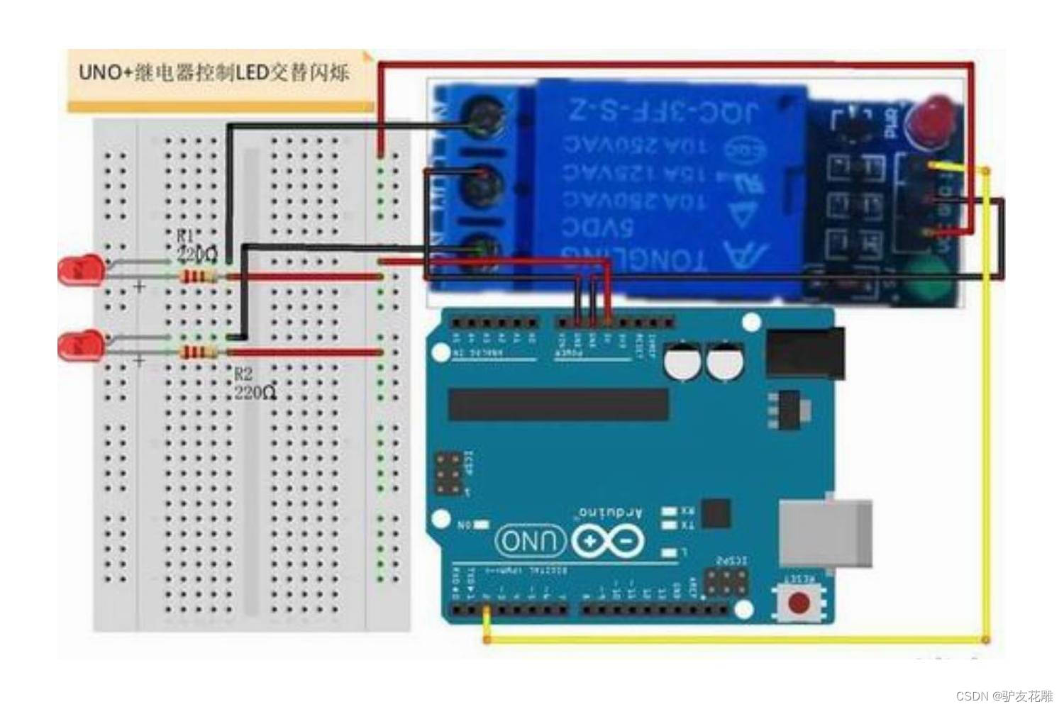
Experiment: The cycle control relay module is closed for 2 seconds and disconnected for 5 seconds (the green light is on and off).
Experiment 1 refers to the open source code (Arduino):
/*
  【Arduino】168种传感器模块系列实验(资料代码+仿真编程+图形编程)
  实验一:循环控制继电器模块吸合2秒断开5秒(绿色吸合指示灯亮灭)
  使用模块:高电平触发5V继电器模块
  实验接线:
  继电器模块  Uno
  VCC        Vcc
  GND        GND
  IN         D8
*/

int jidianqi = 8; //D8脚接继电器模块

void setup() {


  pinMode(jidianqi, OUTPUT); // 设置D8为输出端
}

void loop() {


  digitalWrite(jidianqi, HIGH); //打开继电器模块上的绿色LED灯(吸合)
  delay(2000); //延时2秒
  digitalWrite(jidianqi, LOW); //关闭继电器模块上的绿色LED灯(断开)
  delay(5000); //延时5秒
}
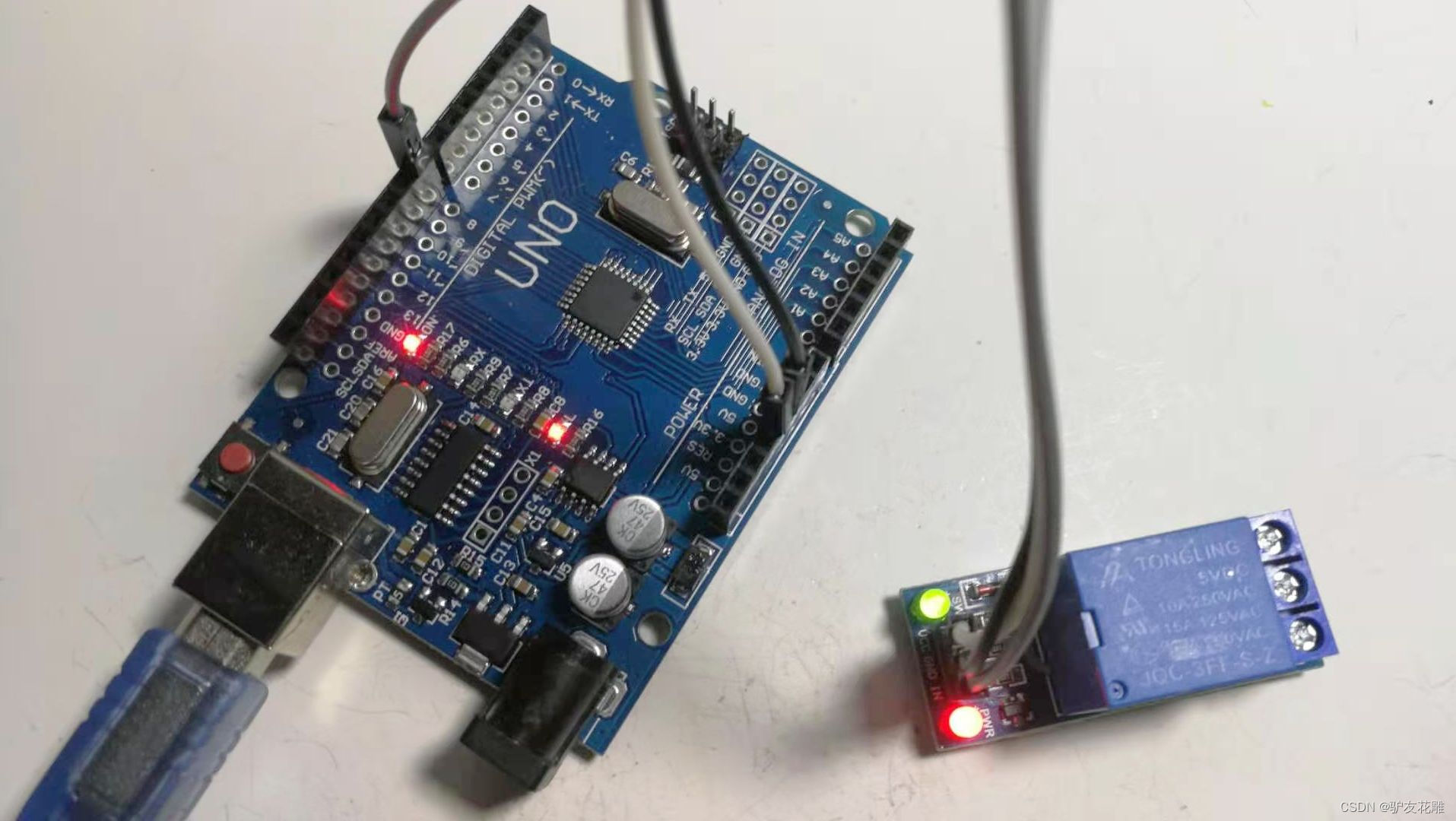
2. Experiment 1 scene diagram
3. Experiment 2 Open source simulation programming (Linkboy V4.2)

4. Experiment 3 Open Source Graphics Programming (Mind+, Learning by Playing)

3. Experiment: Realize bistable control relay module with key switch
1. Experiment 4 Refer to open source code (Arduino):
/*
  【Arduino】168种传感器模块系列实验(资料代码+仿真编程+图形编程)
  实验四:用按键开关实现双稳态控制继电器模块
  使用:高电平触发5V继电器模块与下拉电阻按键模块
  接线:D2接按键模块,D13为板载LED灯
  继电器模块  Uno
  VCC        Vcc
  GND        GND
  IN         D8
*/

int jidianqi = 8; //D8脚接继电器模块
int led = 13; //D13脚接LED灯

void setup() {


  pinMode(2 , INPUT);
  pinMode(jidianqi , OUTPUT); //使用继电器作为控制对象
  pinMode(led , OUTPUT); //使用板载LED作为同步指示灯
}

void loop() {


  if (HIGH == digitalRead(2)) {

      //如果按钮2按下
    digitalWrite(jidianqi , LOW == digitalRead(jidianqi)   ?  HIGH  : LOW );
    digitalWrite(led , LOW == digitalRead(led)   ?  HIGH  : LOW );
    //则反转继电器与led灯的状态,实现双稳态的自锁控制
    delay(500);
  }
}
2. Experiment 5 Open source simulation programming (Linkboy V4.2)
