1. One-arm routing
1. Overview of one-arm routing
One-arm routing (router-on-a-stick) refers to the realization of different VLANs (virtual LAN) interconnection between.

Link type for VLAN:
- The port connecting the switch to the host is an access link
- The port connecting the switch to the router is a trunk link
- The Layer 3 interface of the router cannot be configured as the link type trunk of the switch
Divide subinterfaces on the router:
- A router's physical interface can be divided into multiple logical interfaces
- Each sub-interface corresponds to the gateway of a VLAN network segment
2. One-arm routing principle
The router re-encapsulates the MAC address and converts the VLAN tag
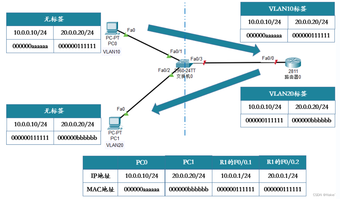
Take the above picture as an example, PC0 needs to send data to PC1, and finds that PC1 is not in the same network segment as itself, then sends the data to its own gateway, which is the F0/0.1 sub-interface of router 0, and obtains its own gateway through the ARP protocol MAC address, the data will be forwarded through the switch.
After arriving at the switch, it will label the received data with a vlan label 10, and transmit the data to router 0. After receiving the data, router 0 gathers the working principle of the router, checks the destination IP address, finds the corresponding interface, performs label conversion, and then sends To the switch, what the switch receives at this time is the data tagged with vlan20, and it is directly forwarded according to the corresponding relationship of the exchanged mac address table.
3. Configuration of one-arm routing
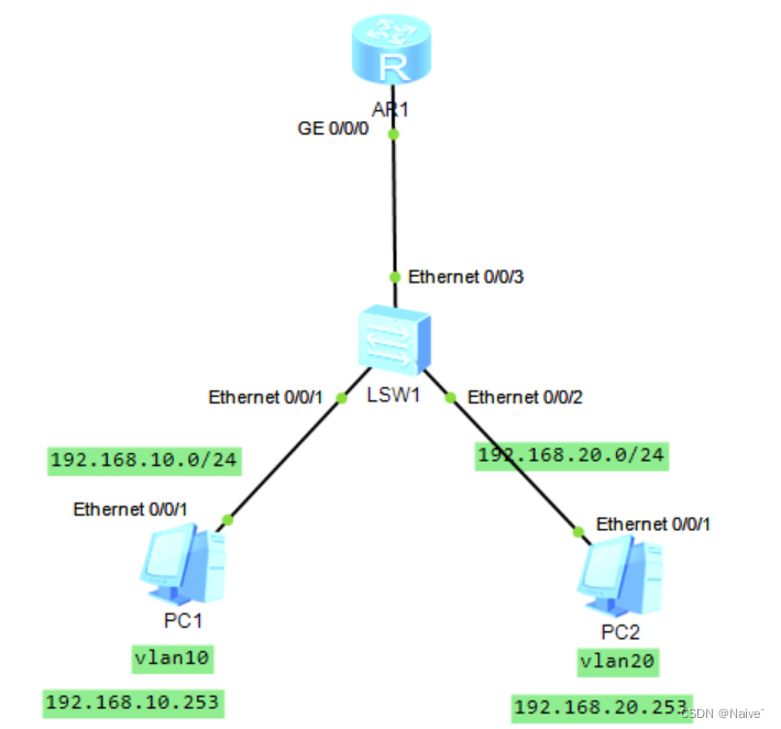
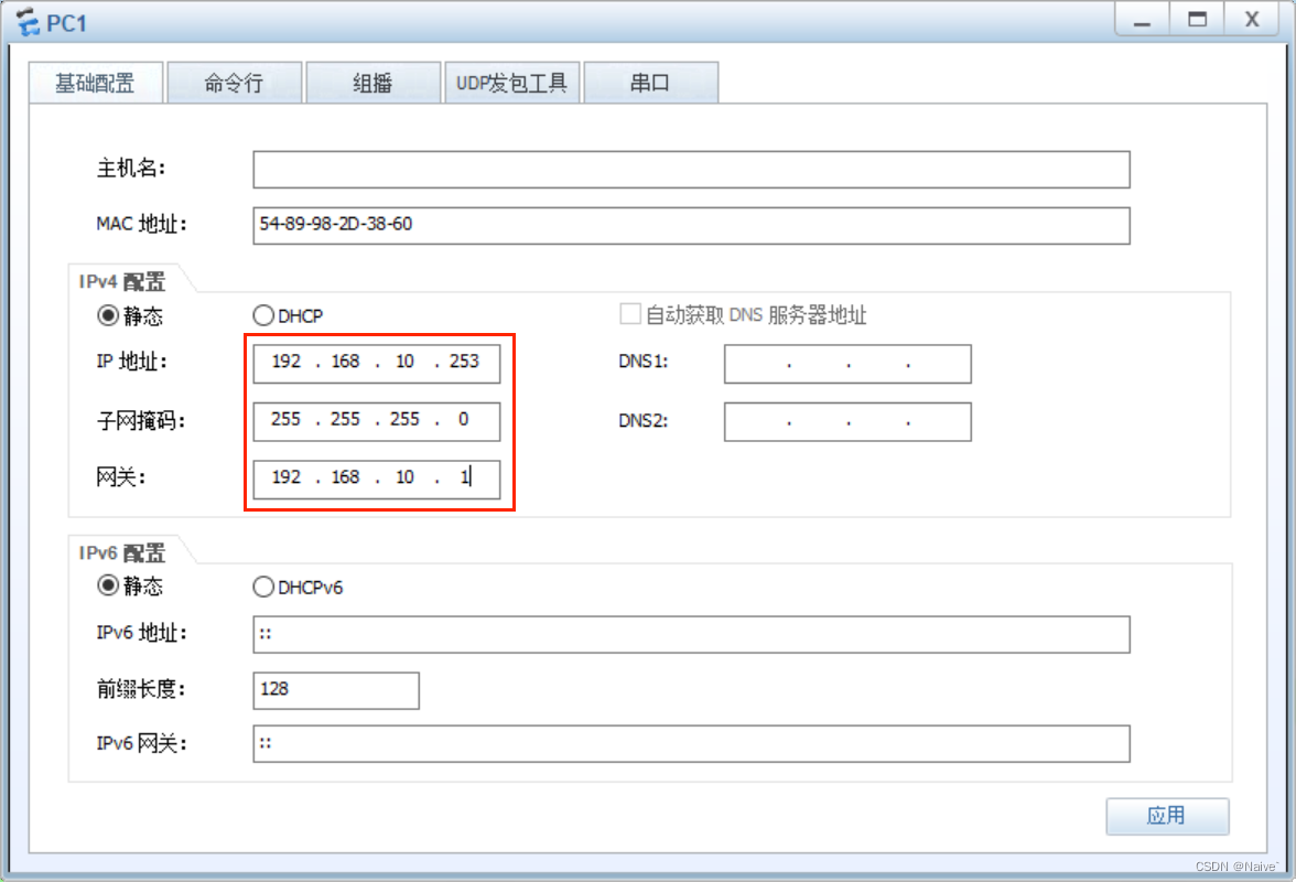
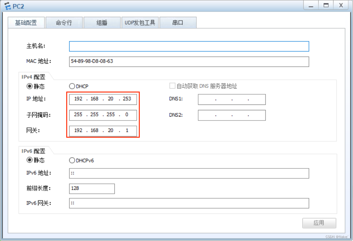
1. Configure the TCP/IP parameters of PC1 and PC2
2. Configure switch LSW1:
<Huawei>sys                 #进入系统视图
Enter system view, return user view with Ctrl+Z.
[Huawei]undo info en        #关闭提示信息
Info: Information center is disabled.
[Huawei]vlan batch 10 20    #创建VLAN10和VLAN20
Info: This operation may take a few seconds. Please wait for a moment...done.
[Huawei]int e0/0/1          #进入e0/0/1接口
[Huawei-Ethernet0/0/1]port link-type access    #配置接口类型为access
[Huawei-Ethernet0/0/1]port default vlan 10     #配置接口的缺省VLAN并同时加入VLAN10
[Huawei-Ethernet0/0/1]int e0/0/2
[Huawei-Ethernet0/0/2]port link-type access
[Huawei-Ethernet0/0/2]port default vlan 20
[Huawei-Ethernet0/0/2]int e0/0/3
[Huawei-Ethernet0/0/3]port link-type trunk     #配置接口类型为trunk
[Huawei-Ethernet0/0/3]port trunk allow-pass vlan 10 20    #配置trunk类型接口可以承载VLAN10和VLAN20
3. Configure single-arm routing on router AR1 to realize intercommunication between PC1 and PC2
<Huawei>sys
[Huawei]undo info en
[Huawei]int g0/0/0.10 #交换机可以子接口划分,直接进入子接口0.10,建议与vlan一致
[Huawei-GigabitEthernet0/0/0.10]dot1q termination vid 10 #配置vlan封装结构,(dot1q为IEEE802.1q协议,该子接口属于vlan10)
[Huawei-GigabitEthernet0/0/0.10]ip address 192.168.10.1 24 #为该子接口添加ip地址(即vlan10下面所属主机的网关地址)
[Huawei-GigabitEthernet0/0/0.10]arp broadcast enable #开启向下arp广播请求功能
[Huawei-GigabitEthernet0/0/0.10]int g0/0/0.20 #进入子接口0.20,建议与对应的vlan一致
[Huawei-GigabitEthernet0/0/0.20]dot1q termination vid 20
[Huawei-GigabitEthernet0/0/0.20]ip address 192.168.20.1 24
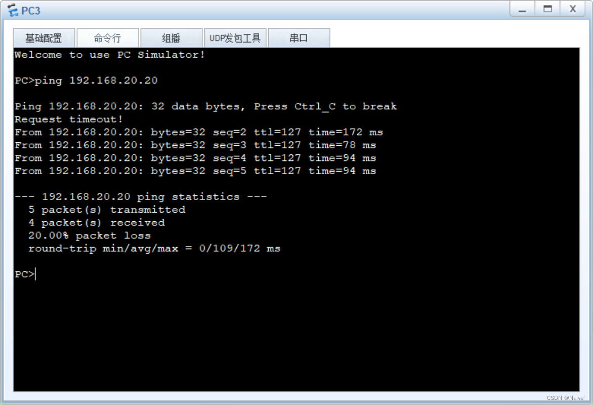
[Huawei-GigabitEthernet0/0/0.20]arp broadcast enable 4. Use PC2 to PingPC1

4. Disadvantages of single-arm routing
- "Single arm" is the backbone link of the network, which is easy to form a network bottleneck
- For forwarding between VLANs, you need to check the routing table, which seriously wastes device resources.
- The sub-interface still relies on the physical interface, and the application is not flexible
Layer 2 and layer 3 switching
1. The introduction of three-layer switching technology
Because one-arm routing adopts the method of dividing sub-interfaces on the router, and the sub-interfaces rely on physical interfaces, all vlan traffic will be forwarded through a physical interface, so the pressure on the physical interface is too large, which will easily cause network congestion, so The three-layer switching technology was introduced to realize VLAN communication between different networks.
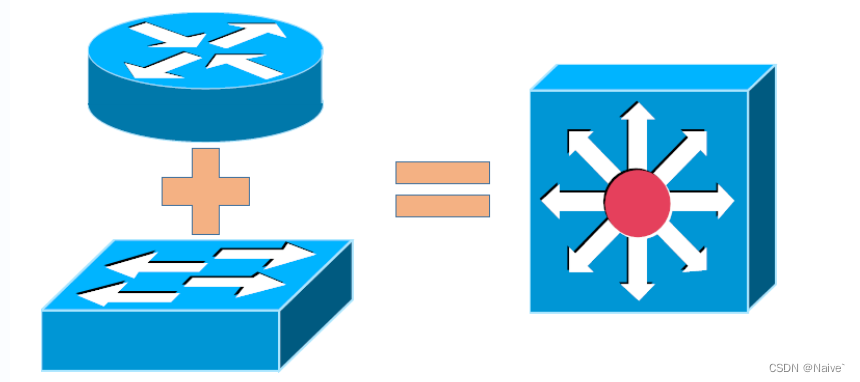
Layer 3 switching technology is: Layer 2 switching technology + Layer 3 forwarding technology . It solves the situation that after the network segment is divided in the LAN, the subnet in the network segment must rely on the router for management, and solves the network bottleneck problem caused by the low speed and complexity of the traditional router.
2. Layer 3 switch forwarding principle
1), traditional MLS (Multilayer Switching)
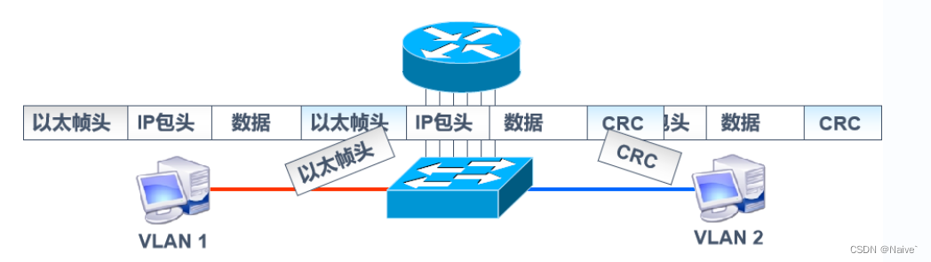
When a Layer 3 device receives a data frame, it will tear down the original data frame, repackage the new source MAC address and destination MAC address, and because the information in the frame header changes, the final frame check CRC should also change accordingly. Of the multiple data packets in this flow, only the first data packet is processed by the Layer 3 engine of the Layer 3 switch, and the processing method is software.
Like a router, the Layer 3 engine routes the packet after obtaining the new Layer 2 encapsulation information. After the first packet is forwarded, an MLS entry is created in hardware for subsequent packet re-encapsulation and fast forwarding performed by the hardware. Layer 2 data frames will be re-encapsulated into the frame format of the next network segment that needs to be forwarded. This is the principle of " one route, many exchanges " of MLS.
- On a Layer 3 switch, the Layer 3 engine processes the first packet of the data flow

- The switching ASIC learns the Layer 2 rewrite information from the Layer 3 engine and creates an MLS entry in hardware responsible for rewriting and forwarding subsequent packets in the data flow
2), CEF-based MLS
The key to the MLS based on CEF (a model based on topology forwarding) is two forwarding information tables, and the forwarding information base (FIB) corresponds to the routing table one by one, which is a mirror image of the routing table. When the routing table is updated, the FIB changes accordingly, and the FIB includes the correspondence between the IP addresses of adjacent hosts and VLAN IDs. The adjacency table contains the correspondence between the adjacent hosts and the MAC addresses of the switches to provide Layer 2 rewriting information.
The CEF-based MLS forwarding process is to send a unicast data packet, and re-encapsulate the data frame by searching the FIB and the adjacency table, and forward it from the corresponding port.

3. Introduction of virtual interface (forwarding process of communication between Layer 3 switch VLANs)
1) The interfaces on the Layer 3 switch belong to different VLANs
Host A sends data to host B, host A belongs to VLAN 10, host B belongs to VLAN 20, host A sends data to the vlan 10 interface of the three-layer switch, imports the vlan 10 virtual interface of the three-layer switch, and the vlan 10 virtual interface The interface is forwarded to the vlan 20 virtual interface, and then forwarded through the physical interface belonging to vlan 20.

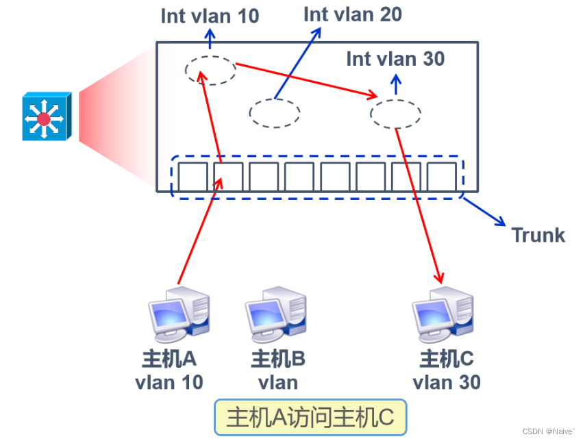
2) All interfaces on the Layer 3 switch belong to the trunk interface
Host A sends data to host C, host A belongs to vlan10, host C belongs to vlan30, all interfaces of the three-layer switch belong to trunk, all interfaces of the three-layer switch can receive and forward all vlan data, after the data of host A comes in through the trunk, remove Label, according to the destination IP, it is found that the data needs to be sent to vlan30, label it with vlan30, and forward it through the trunk interface. There must be a layer 2 switch to receive it. After receiving the data, the layer 2 switch removes the label and sends it to vlan30 the host.
4. Layer 3 switching configuration
- Configure the VLAN interface as a virtual interface on the Layer 3 switch
When the corresponding vlan is created on the switch, the corresponding virtual interface is automatically generated. The default virtual interface on the switch is vlan1, and the corresponding virtual interface is directly used as the gateway of the corresponding vlan.
<Huawei>sys
[Huawei]interface vlan 10                      #进入虚接口(需要提前创建VLAN)
[Huawei-Vlanif10]ip address 192.168.10.1 24 #配置虚拟口的IP- Experimental case
Steps to configure Layer 3 switching:
1. Create a VLAN on the Layer 2 switch and add the interface to the corresponding VLAN
2. The interface connecting the Layer 2 switch and the Layer 3 switch needs to carry multiple VLANs
3. The building connected by the layer-3 switch and the layer-2 switch needs to carry multiple VLANs
4. Layer 3 switches introduce virtual interfaces
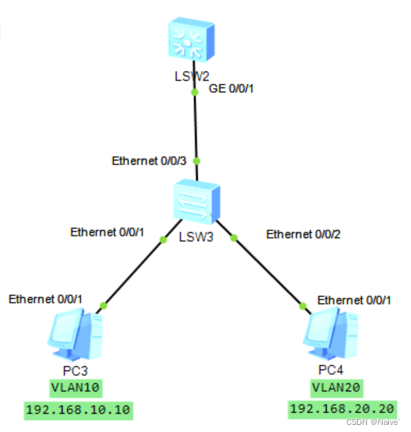
1. Statically configure the TCP/IP parameters of PC3 and PC4


2. Configure the Layer 2 switch LSW3
<Huawei>system
[Huawei]vlan batch 10 20
Info: This operation may take a few seconds. Please wait for a moment...done.
[Huawei]int e0/0/1
[Huawei-Ethernet0/0/1]port link-type access
[Huawei-Ethernet0/0/1]port default vlan 10
[Huawei-Ethernet0/0/1]int e0/0/2
[Huawei-Ethernet0/0/2]port link-type access
[Huawei-Ethernet0/0/2]port default vlan 20
[Huawei-Ethernet0/0/2]int e0/0/3
[Huawei-Ethernet0/0/3]port link-type trunk
[Huawei-Ethernet0/0/3]port trunk allow-pass vlan 10 20
3. Configure a Layer 3 switch
<Huawei>sys
[Huawei]vlan batch 10 20
Info: This operation may take a few seconds. Please wait for a moment...done.
[Huawei]int g0/0/1
[Huawei-GigabitEthernet0/0/1]port link-type trunk
[Huawei-GigabitEthernet0/0/1]port trunk allow-pass vlan 10 20

[Huawei-GigabitEthernet0/0/1]int vlan 10    #进入虚接口vlan 10并设置IP地址(即vlan10下面所属主机的网关地址)
[Huawei-Vlanif10]ip add 192.168.10.254 24

[Huawei-Vlanif10]int vlan 20       #进入虚接口vlan 20并设置IP地址(即vlan20下面所属主机的网关地址)
[Huawei-Vlanif20]ip add 192.168.20.254 24
4. Use PC3 to PingPC4