Introduction and experimental operation of single-arm routing and three-layer switch
One-arm routing
1. Background
Before, we can effectively divide the LAN through learning VLAN, and realize the access control between each network area. But in reality, it is often necessary to configure the interconnection and intercommunication between certain VLANs. For example, your company is divided into leadership, sales, finance, human resources, science and technology, and auditing. Different departments are configured with different VLANs, and the departments cannot access each other, effectively ensuring the information security of each department. . But it often appears that the leadership needs to cross the VLAN to visit other departments, this function is realized by single-arm routing.
One-arm routing (router-on-a-stick) refers to the realization of different VLANs (virtual LAN) interconnection and intercommunication.
In simple terms, single-arm routing is used to realize the communication between different VLANs after being divided.
Link type: The
port connecting the switch to the host is an access link, and the
port connecting the switch to the router is a trunk. The link has
sub-interfaces
. The physical interface of the router can be divided into multiple logical interfaces.
Each sub-interface corresponds to a VLAN network segment.

2. Overview of single-arm routing
One-arm routing realizes the communication principle between different VLANs. The
router re-encapsulates the MAC address and converts the VLAN tag.

3. Single-arm routing experiment operation based on eNSP
Detailed steps
1. Prepare the network topology diagram, and the connection is started

2. Divide the required Vlan

3. Configure the interface connecting the switch to the PC (here we know that it is all through the access interface)
(1) Switch the switch Configure the VLAN (PLA and PD V+vlan number steps)
on the
interface connected to the PC on the specific operation command: here, configure the other ACCESS interfaces connected to the PC in the same way (the other is also configured in the same way)
(2) Configure the switch to connect to the router The
specific operation of the interface (trunk port) is as follows:

4. Configure the router
(1) As you can see from the figure, we need to configure two sub-interfaces, where the sub-interface is equivalent to the gateway.

Ps : When configuring the second sub-interface, I forgot to configure the second gateway address, which resulted in the failure to ping afterwards, and it was correct if I added it later.
(2) Go back to the parent interface of the two sub-interfaces and enter "un sh" to turn on all the interfaces starting with 0.
(3) Go to the PC command to PING, and both sides can be pinged successfully,


until both sides can be pinged. , That is, the experiment of single-arm routing across VLAN is successful!
Layer 2 and 3 switching technology
1. Three-layer exchange
Layer 3 switching technology can realize inter-VLAN communication Layer 3 switching = Layer 2 switching + Layer 3 forwarding
When the Layer 3 device receives a data frame, it will tear down the original data frame and re-encapsulate the new source Mac address and destination MAC address, and because the information in the frame header changes, the final frame check CRC should also change accordingly.

Among the multiple data packets in this flow, only the first data packet is processed by the three-layer engine of the three-layer switch. The processing method is software, which is the same as the router. The three-layer engine obtains a new layer 2 encapsulation. After the information, route the packet.
2. Traditional MLS
After the first data packet is forwarded, an MLS entry is created in the hardware for re-encapsulation and fast forwarding of subsequent data packets performed by the hardware. Layer 2 data frames will be re-encapsulated into the frame format of the next network segment that needs to be forwarded.
This is the principle of MLS " route once, exchange many times ".
3. MLS based on CEF
The key to MLS based on CEF (a model based on topology forwarding) is two forwarding information tables. The forwarding information base (FIB) corresponds to the routing
table one by one, which is a mirror image of the routing table. When the routing table is updated, the FIB changes accordingly, and the FIB contains
the correspondence between the IP address of the adjacent host and the VLANID . The adjacency relationship table contains the corresponding relationship between the adjacent host and the switch MAc address to provide layer 2 rewriting information.

The CEF-based MLS forwarding process is to send unicast data packets, re-encapsulate the data frame by looking up the FIB and adjacency table, and forward it from the corresponding port.
4. Virtual interface
The Layer 3 switch has the routing function, so the two VLANs can access each other, and each
VLAN virtual interface is the gateway of the network segment. Here are the settings in the Layer 3 switch.
Three based on eNSP three-layer exchange simulation experiment
Detailed steps
1. Draw the required network topology diagram, and complete the device connection as shown in the figure below
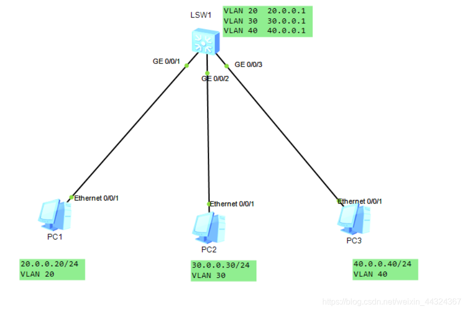
2. Divide the VLAN we need in eNSP, here we know that they are VLAN 20 30 40 respectively.
The specific operation command
vlan batch 10 20 30 ------------ Here we have divided 3 VLANs in our switch. As shown in the figure

3. Configure the ports connected to each PC in the three-layer switch
(1). First determine the interface type for the PC to access the three-layer switch.
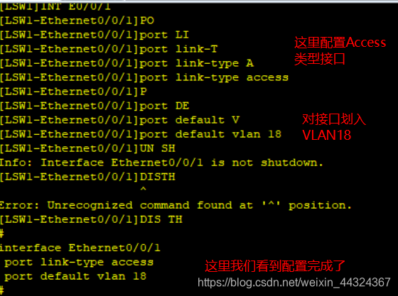
Here is the ACCESS interface type, the specific operation command is:
port link-type access (PLA) ----- Here, set the interface type to ACCESS
(2). Put the specific interface into the divided VLAN in the interface mode .
The specific operation command is: port default vlan 20 (or PDV 20)
and then remember to enter: un sh (here is to open the current interface)
here, operate the remaining interfaces in sequence. As shown in the figure:

(3) Configure the virtual interface of VLAN on the three-layer switch (the three-layer switch has the routing function, so you can configure the virtual interface)

Here, if you don’t know what is not configured, you can enter dis cur and press the tab key and press Enter to check the configuration, as shown in the figure:

here we check it is no problem.
4. Use the PING command to check whether the cross-network segment communication is realized through the three-layer switch. It


is found that the three PCs can communicate with each other, so the three-layer switch simulation experiment is successful.