H264 encoding (intra prediction)
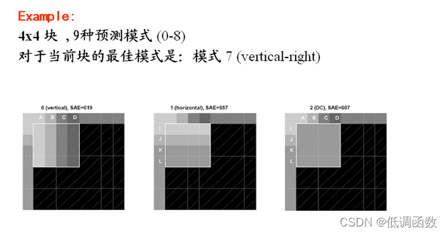
In intra prediction mode, the predicted block P is formed based on the coded reconstruction block and the current block. For luma pixels, P blocks are used for correlation operations on 4×4 sub-blocks or 16×16 macroblocks. 4×4 luminance sub-blocks have 9 optional prediction modes, independently predict each 4×4 luminance sub-block, which is suitable for image coding with a lot of details; 16×16 luminance blocks have 4 prediction modes, predict the entire 16× 16 luma blocks, suitable for image coding in flat areas; chroma blocks also have 4 prediction modes, similar to 16×16 luma block prediction modes. The encoder typically chooses the prediction mode that minimizes the difference between the P-block and the coded block.
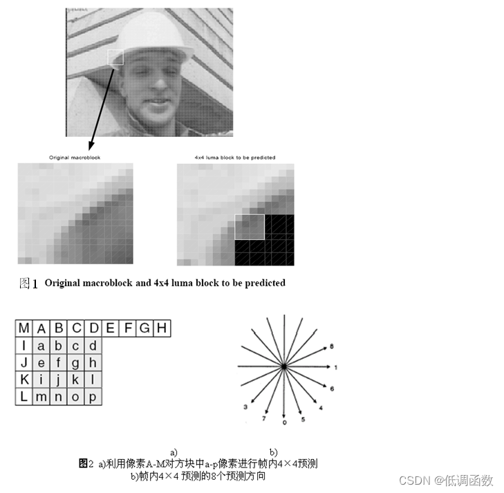
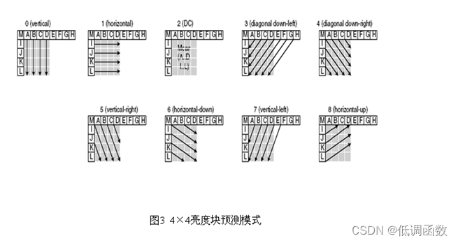
4×4 luma prediction mode
As shown in Figure 6.14, the upper and left pixels A~M of the 4×4 luma block are encoded and reconstructed pixels, which are used as prediction reference pixels in the codec. a~p are the pixels to be predicted, which are realized by using A~M values and 9 modes. Among them, the mode 2 (DC prediction) is predicted according to the coded pixels in A~M, and the other modes can only be used when all the required prediction pixels are provided. Figure 6.15 Arrows indicate the direction of prediction for each mode. For modes 3-8, the predicted pixels are obtained by weighted average of A-M. For example, in mode 4, d=round(B/4+C/2+D/4).
| model | describe |
|---|---|
| mode 0 (vertical) | Vertically push out the corresponding pixel values from A, B, C, D |
| Mode 1 (horizontal) | Corresponding pixel value derived from I, J, K, L levels |
| Mode 2 (DC) | Deduce all pixel values from the average value of A~D and I~L |
| Mode 3 (lower left diagonal) | The corresponding pixel value is obtained by pixel interpolation in the 45° direction |
| Mode 4 (lower right diagonal) | The corresponding pixel value is obtained by pixel interpolation in the 45° direction |
| Mode 5 (right vertical) | The corresponding pixel value is obtained by interpolating the pixel value in the 26.6° direction |
| Mode 6 (lower level) | The corresponding pixel value is obtained by interpolating the pixel value in the 26.6° direction |
| Mode 7 (left vertical) | The corresponding pixel value is obtained by interpolating the pixel value in the 26.6° direction |
| Mode 8 (upper level) | The corresponding pixel value is obtained by interpolating the pixel value in the 26.6° direction |
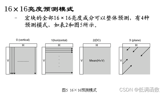
16×16 prediction mode
![[External link picture transfer failed, the source site may have an anti-leeching mechanism, it is recommended to save the picture and upload it directly (img-5Rt0ISof-1690336701808)(img/18.png)]](https://img-blog.csdnimg.cn/331df8e51c6d4907952d35a57a63238a.png)
| model | describe |
|---|---|
| mode 0 (vertical) | Deduce the corresponding pixel value from the upper pixel |
| Mode 1 (horizontal) | Deduce the corresponding pixel value from the left pixel |
| Mode 2 (DC) | The corresponding pixel value is derived from the average value of the upper and left pixels |
| Mode 3 (flat) | Use the linear "plane" function and the left and upper pixels to derive the corresponding pixel values, suitable for areas with gentle brightness changes |
8×8 Chroma Block Prediction Mode
The 8×8 chrominance components of each intra-coded macroblock are predicted from the coded upper left chrominance pixels, and the two chrominance components usually use the same prediction mode.
The 4 prediction modes are similar to the 4 prediction modes of intra 16×16 prediction, but the mode numbers are different. Among them, DC (Mode 0), Horizontal (Mode 1), Vertical (Mode 2), and Plane (Mode 3).
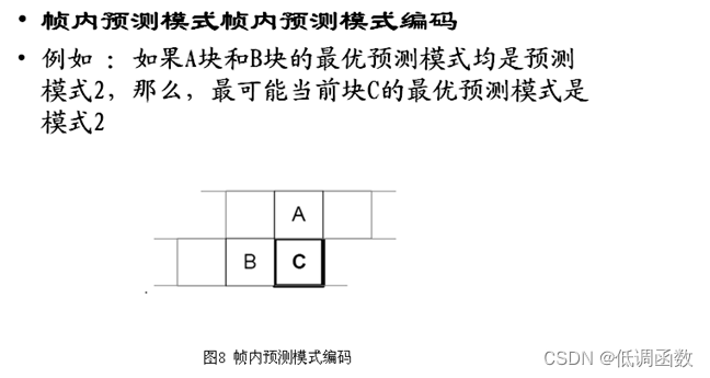
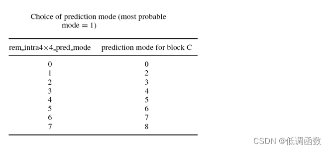
For the current block C, the codec is calculated as follows
probableprediction mode=
min{prediction mode of A, predictionmodes of B}
当A (或者 B)的预测模式不可用时,
prediction mode of A= 2.
For example
The prediction modes for A and B blocks are 3 and 1, respectively
most probable mode for block C =1
The encoder sends a flag for each 4x4 block, and the decoder decodes as follows
Ifflag==1, prediction mode=most_probable_mode
Ifflag==0
If rem_intra4×4_pred_mode< most_probable_mode
prediction mode=rem_intra4×4_pred_mode
else
prediction mode=rem_intra4×4_pred_mode+1
This means that only 8 values (0 to 7) are required for the 9 prediction modes