a brief introduction
The focus of the pinctrl
subsystem is to set
the multiplexing and electrical properties of
PIN (
some
SOCs
are called
PAD) ,
If the pinctrl subsystem
multiplexes
a
PIN as
GPIO , then the gpio subsystem will be used next. As the name suggests, the gpio subsystem is used to initialize GPIO and provide corresponding API functions, such as setting GPIO
For input and output, read the value of
GPIO
, etc.
The main purpose of the gpio
subsystem is to facilitate driver developers to use
gpio
, drive
Developers add gpio- related information
in the device tree , and then they can use the API provided by the gpio subsystem
in the driver
function to operate
GPIO
,
the Linux
kernel shields the driver developer from the
GPIO
setting process, which greatly facilitates the driver development
The sender uses
GPIO
.
1.1 , gpio information in the device tree
There are some routines for setting the node properties of a device, query the documents in the kernel, such as Documentation/devicetree/bindings/i2c/i2c-imx.txt describes the i2c property setting method of the imx platform
The UART1_RTS_B on the I.MX6ULL-ALPHA
development board
is used as the detection pin of the SD card, and the UART1_RTS_B complex
It is used as
GPIO1_IO19
, by reading the high and low levels of this
GPIO
, you can know whether
the SD
card is inserted or not.
First of all it must be
Multiplex the
PIN of
UART1_RTS_B
as GPIO1_IO19 , and set the electrical properties, which is what was mentioned in the previous section
pinctrl
node. Open
imx6ull-alientek-emmc.dts
,
the pincrtl setting of
UART1_RTS_B
PIN is as follows:
示例代码 45.2.2.1 SD 卡 CD 引脚 PIN 配置参数
316 pinctrl_hog_1: hoggrp-1 {
317 fsl,pins = <
318 MX6UL_PAD_UART1_RTS_B__GPIO1_IO19 0x17059 /* SD1 CD */
......
322 >;
323 };
After
the pinctrl is configured,
the gpio
is set.
The SD
card driver
judges the SD card by reading the value of
GPIO1_IO19 .
The card is inserted or not, but how does
the SD
card driver know
which GPIO1_IO19 the
CD
pin is connected to
? definitely need to set
Prepare the tree to tell the driver!
Add an attribute under the SD card node
in the device tree
to describe
the CD pin of
the SD card.
示例代码 45.2.2.2 设备树中 SD 卡节点
760 &usdhc1 {
761 pinctrl-names = "default", "state_100mhz", "state_200mhz";
762 pinctrl-0 = <&pinctrl_usdhc1>;
763 pinctrl-1 = <&pinctrl_usdhc1_100mhz>;
764 pinctrl-2 = <&pinctrl_usdhc1_200mhz>;
765 /* pinctrl-3 = <&pinctrl_hog_1>; */
766 cd-gpios = <&gpio1 19 GPIO_ACTIVE_LOW>;
767 keep-power-in-suspend;
768 enable-sdio-wakeup;
769 vmmc-supply = <®_sd1_vmmc>;
770 status = "okay";
771 };cd - gpios = <& gpio1 19 GPIO_ACTIVE_LOW >;
The attribute "
cd-gpios
" describes which
IO is used by
the SD
card's
CD pin
. There are three attribute values,
Let's take a look at the meaning of these three attribute values, "
&gpio1
" means that
the IO used by
the CD pin
belongs to the GPIO1 group, " 19 "
Indicates
the 19th IO of
the GPIO1
group
. Through these two values, the SD card driver knows that the CD pin uses GPIO1_IO19
This
GPIO
. "
GPIO_ACTIVE_LOW
" means low level
1
is active, if changed to "
GPIO_ACTIVE_HIGH
" means
Indicates that high level
0
is valid.
Example code 45.2.2.2 gpio1 node504 gpio1 : gpio@0209c000 {505 compatible = "fsl,imx6ul-gpio" , "fsl,imx35-gpio" ;506 reg = < 0x0209c000 0x4000 >;507 interrupts = < GIC_SPI 66 IRQ_TYPE_LEVEL_HIGH >,508 < GIC_SPI 67 IRQ_TYPE_LEVEL_HIGH >;509 gpio - controller ;510 #gpio - cells = < 2 >;511 interrupt - controller ;512 #interrupt - cells = < 2 >;513 };
The gpio1
node information describes
all the information of the
GPIO1 controller, focusing on
the base address of the GPIO1 peripheral register and
compatible properties.
Please refer to the document for the GPIO controller binding information of
the I.MX
series
SOC
Documentation/devicetree/bindings/gpio/ fsl-imx-gpio.txt
。
In line
505
, there are two
compatible attributes of the
gpio1
node
, which are " fsl,imx6ul-gpio " and " fsl,imx35-
gpio
",
you can find the GPIO driver of I.MX6UL by searching for these two strings in
the Linux kernel.
Line
506
,
the reg
attribute sets
the register base address of the
GPIO1 controller to
0X0209C000,
Line
509
, "
gpio-controller
" indicates that the
gpio1
node is a
GPIO
controller.
Line
510
, the "
#gpio-cells
" attribute is similar to "
#address-cells
",
#gpio-cells
should be
2
, indicating that there are
Two
cells
, the first
cell
is
the GPIO number
, such as "
&gpio1 3
" means
GPIO1_IO03
. The second
cell
represents
GPIO polarity
.
1.2 Add gpio node to device tree
Create a test device subnode under the root node "/":
Add pinctrl information
Add GPIO attribute information
test {
    pinctrl-names = "default";
    pinctrl-0 = <&pinctrl_test>;
    gpio = <&gpio1 0 GPIO_ACTIVE_LOW>;
}
Two GPIO Driver Introduction
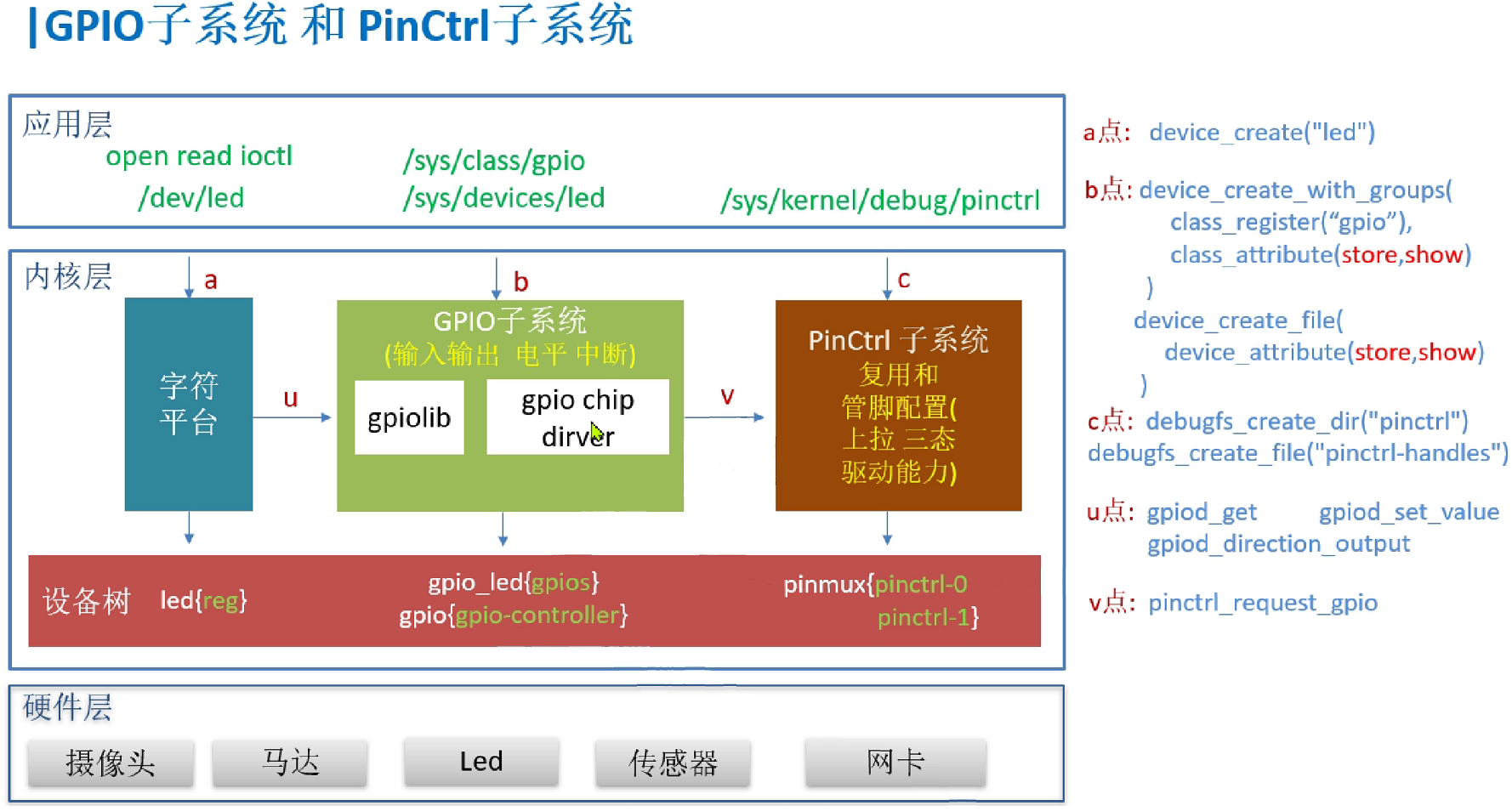
The following figure is the gpio and pinctrl subsystem architecture diagram
2.1 How to get gpio information from the device tree
Reading gpio information in the linux device tree is realized by operating the gpiolib library. This library is driven by the layered thinking of linux device management.
- First get the device node of_find_node_by_path where gpio is located
- Get the gpio number of_get_named_gpio
- Request the gpio gpio_request function for this number
- Set gpio input and output gpio_direction_input or gpio_direction_outout
- gpio input and output value setting gpio_get_value /gpio_set_value
2.2 gpio api
The commonly used API functions provided by the gpio subsystem are as follows:
1.
gpio_request function
_
The gpio_request
function is used to apply for a
GPIO
pin,
be sure to use gpio_request before using a
GPIO
To apply, the function prototype is as follows:
int gpio_request(unsigned gpio, const char *label)
Function parameters and return values have the following meanings:
gpio
: the gpio label
to apply for
, use the of_get_named_gpio function to obtain the specified GPIO attribute information from the device tree
information, this function will return the label of this
GPIO
.
label
:
Set a name for
gpio .
Return value:
0
, the application is successful; other values, the application fails.
2.
gpio_free function
_
If a
GPIO is not used, then the
gpio_free function
can be called
to release it. The function prototype is as follows:
void gpio_free(unsigned gpio)
Function parameters and return values have the following meanings:
gpio
: The gpio label
to release
.
Return value:
None.
3.
gpio_direction_input function
_
This function is used to set a
GPIO
as an input, and the function prototype is as follows:
int gpio_direction_input(unsigned gpio)
Function parameters and return values have the following meanings:
gpio
: GPIO number
to set as input .
Return value:
0
, the setting is successful; negative value, the setting fails.
4.
gpio_direction_output function
_
This function is used to set a
GPIO
as an output and set the default output value. The function prototype is as follows:
int gpio_direction_output(unsigned gpio, int value)
Function parameters and return values have the following meanings:
gpio
: GPIO number
to set as output .
value
:
GPIO
default output value.
Return value:
0
, the setting is successful; negative value, the setting fails.
5.
gpio_get_value function
_
This function is used to get
the value (0 or 1) of a
GPIO
. This function is a macro, as shown in the definition:
#define gpio_get_value __gpio_get_value
int __gpio_get_value(unsigned gpio)
Function parameters and return values have the following meanings:
gpio
: The GPIO number
to get
.
Return value:
non-negative value, the obtained
GPIO
value; negative value, failure to obtain.
6.
gpio_set_value function
_
This function is used to set the value of a
GPIO
, this function is a macro, defined as follows
#define gpio_set_value __gpio_set_value
void __gpio_set_value(unsigned gpio, int value)
Function parameters and return values have the following meanings:
gpio
: GPIO label
to be set
.
value
:
The value to set.
Return value:
None
These are the API functions commonly used in the gpio subsystem ,
and
these are the ones we use the most.
The operation example of gpio will be explained in the platform