Article Directory
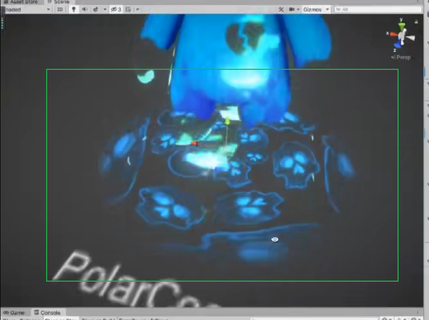
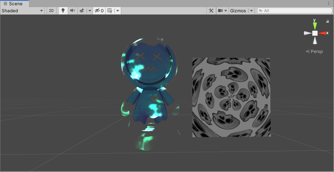
This time, the notes will directly display the final effect, because the teacher did not give code pictures or any technical instructions in the course.
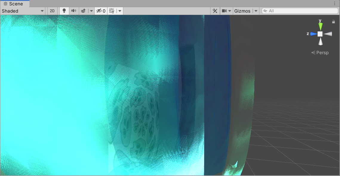
- The left side of the figure below is the frame sequence animation (wisps), and the right side is the polar coordinates.
frame sequence animation
The principle of frame sequence is to sample a sequence of frame textures sorted in regular rows and columns. With the change of time, the content of the displayed textures is different. The sequence frame texture is as follows:
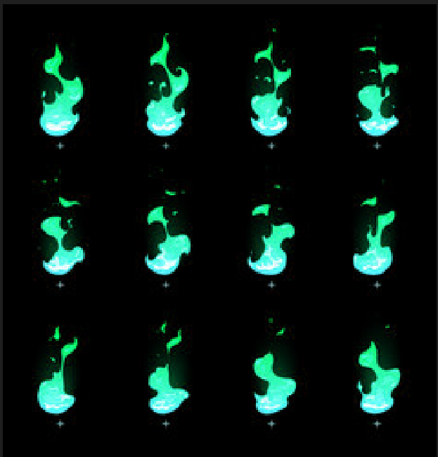
- You can see a series of pictures arranged in regular sizes.
Our principle is:
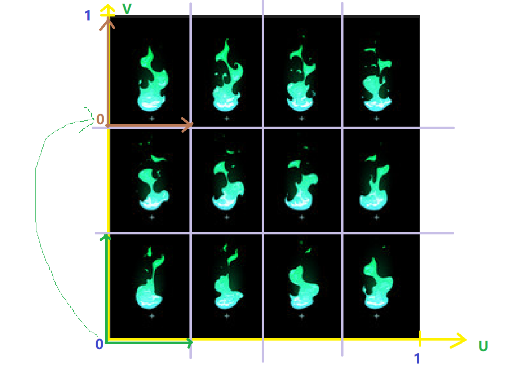
- First of all, the UV coordinates of the whole picture are mainly based on the yellow coordinate system, and the origin is in the lower left corner of the whole picture.
- In order to get each small picture, we need to cut this texture and divide each small picture equally, so that we can switch small pictures later.
- We need to convert the large UV into a small image UV. So we divide the number of rows and columns by 1, because the value range of large UV is [0,1], and divide 1 by the number of rows and columns to get the value range of uv for each small picture. The value of U becomes [0, 1/number of columns], and the value of V becomes [0,,1/number of rows].
- Note that the UV obtained in the above step becomes the UV of the small picture in the lower left corner, and the origin of the uv coordinates is still the lower left corner.
- But what we want is an order from left to right and from top to bottom, so we need to move the UV origin to the position of the first row and first column.
- After moving the UV coordinates, only one algorithm is needed to switch the next picture, see my code for details.
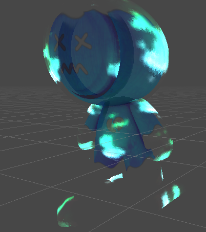
- Our animation is set on the outside of the model like a shell, so we need the vertex normal of the model to offset a certain distance outward along the normal direction to make a shell-like effect.
- The frame sequence animation is done on the shell, so it needs to be processed by the second pass, so this part of the shader uses a double pass.
- The first pass is to sample a main texture normally, using the AB method.
- The second pass uses normals to process frame sequence animation, using the AD method.
the code
Shader "shader forge/L18_FireSequence"
{


    Properties
    {


        _MainTex ("Base Color With A", 2D) = "white" {

    }
        _Opacity ("Opacity", Range(0.0,1.0)) = 0.5
        _Sequence ("Sequence Texture",2D) = "gray" {

    }       //帧序列图
        _RowCount ("Row",Int) = 3                                       //行数
        _ColCount ("Col",Int) = 4                                          //列数
        //_SeqID ("Sequence ID",Int) = 0                                 //帧序列号
        _Speed ("Speed", Range(-10,10)) = 3
    }
    SubShader
    {


    	//主要做的
        Tags {


            "Queue"="Transparent"
            "RenderType" = "Transparent"
            "ForceNoShadowCasting" = "True"
            "IgnoreProjector" = "True"
        }

        Pass
        {


        NAME "FORWARD_AB"

        Tags{


            "LightMode" = "ForwardBase"
        }

        Blend One OneMinusSrcAlpha		//AB

            CGPROGRAM
            #pragma vertex vert
            #pragma fragment frag
            // make fog work
            #pragma multi_compile_fog

            #include "UnityCG.cginc"

            struct appdata
            {


                float4 vertex : POSITION;
                float2 uv0 : TEXCOORD0;
            };

            struct v2f
            {


                float2 uv0 : TEXCOORD0;
                float4 vertex : SV_POSITION;
            };

            uniform sampler2D _MainTex;
            uniform float4 _MainTex_ST;	//我们的贴图偏移选项
            uniform float _Opacity;

            v2f vert (appdata v)
            {


                v2f o;
                o.vertex = UnityObjectToClipPos(v.vertex);
                o.uv0 = TRANSFORM_TEX(v.uv0, _MainTex);		//加上贴图偏移
                return o;
            }

            fixed4 frag (v2f i) : SV_Target
            {


                fixed4 var_MainTex = tex2D(_MainTex, i.uv0);
                float3 finalRGB = var_MainTex.rgb;
                half opacity = var_MainTex.a * _Opacity;
                return float4(finalRGB * opacity, opacity);
            }
            ENDCG
        }

        Pass
        {


        NAME "FORWARD_AD"
        Tags{


            "LightMode" = "ForwardBase"
        }
        Blend One One
        //Cull Front

            CGPROGRAM
            #pragma vertex vert
            #pragma fragment frag
            // make fog work
            #pragma multi_compile_fog

            #include "UnityCG.cginc"

            struct appdata
            {


                float4 vertex : POSITION;
                float4 normal:NORMAL;
                float2 uv : TEXCOORD0;
            };

            struct v2f
            {


                float2 uv : TEXCOORD0;
                float4 pos : SV_POSITION;
            };

            uniform sampler2D _Sequence;
            uniform float4 _Sequence_ST;	//我们的贴图偏移选项
            uniform half _RowCount;     //行数
            uniform half _ColCount;     //列数
            //uniform half _SeqID;            //帧序列号
            uniform half _Speed;

            v2f vert (appdata v)
            {


                v2f o;
                //因为第二个pass是用来处理帧序列动画的,这个动画就像是壳子一样套在原模型的外面一层,所以需要让这个pass的模型顶点位置沿着法线方向增加一定的距离
                v.vertex.xyz += v.normal * 0.003;
                o.pos = UnityObjectToClipPos(v.vertex);
                o.uv = TRANSFORM_TEX(v.uv,_Sequence);       //为了能让它支持Tiling和offset
                half seqID = floor(_Time.z * _Speed);         //根据时间来取序列号
                half rowID = floor(seqID / _ColCount);     //根据_SeqID算出行号
                half ColID = seqID % _ColCount;              //根据_SeqID算出列号
                half stepU = 1.0 / _ColCount;                        //计算每次移动的U值偏移,因为UV坐标的范围都为[0,1]
                half stepV = 1.0 / _RowCount;                       //计算每次移动的V值偏移,因为UV坐标的范围都为[0,1]
                half2 initUV = o.uv * float2(stepU,stepV);      //将uv从范围[0,1]缩放为[stepU,stepV]

                //因为默认uv坐标从左下角开始,我们要做一下缩放,将缩放成单个序列帧uv大小
                initUV += float2(0.0, stepV * (_RowCount - 1));
                //然后做偏移,将图片uv坐标的原点移动到第一个序列帧的uv坐标原点上
                o.uv = initUV + float2(stepU * ColID, -stepV * rowID);
                return o;
            }

            fixed4 frag (v2f i) : SV_Target
            {


                // sample the texture
                fixed4 var_Sequence = tex2D(_Sequence, i.uv);
                fixed3 finalRGB = var_Sequence.rgb;
                fixed opacity = var_Sequence.a;
                return fixed4(finalRGB * opacity, opacity);
            }
            ENDCG
        }
    }
}
final effect
polar coordinates
The polar coordinate part also performs a calculation on UV coordinates, but uses angles and lengths instead of UV coordinates.
As shown below:
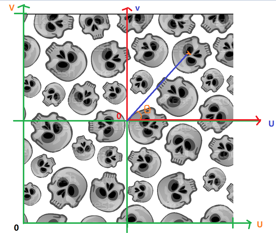
- First of all, the UV coordinates of this texture are the green coordinate system with the origin at the lower left corner of this texture.
- We want to move the UV coordinates to the red coordinate system, and the value range of UV also changes from [0,1] to [-0.5,0.5], and the origin of the coordinate system becomes the center of the picture.
- Then, according to the UV coordinate value, calculate the angle θ of a certain point on the picture, and the length from the origin.
- Because the angle θ is an angle, the value range is [-pi,pi], so we need to change its value range to 0,1
- Get the distance we are looking for from the origin, and add a changing part to it (for animation)
- Then use the angle and length as a new UV to sample the texture, and you can get a polar coordinate animation.
the code
Shader "shader forge/L18_PolarCoord"
{


    Properties
    {


        _MainTex ("Texture", 2D) = "white" {

    }
        _Opacity ("Opacity",Range(0,1)) = 0.5
        _Color ("Color",Color) = (1.0,1.0,1.0,1.0)
    }
    SubShader
    {


        Tags {

     "RenderType"="Opaque" }
        LOD 100

        Pass
        {


            CGPROGRAM
            #pragma vertex vert
            #pragma fragment frag

            #include "UnityCG.cginc"

            struct appdata
            {


                float4 vertex : POSITION;
                float2 uv : TEXCOORD0;
            };

            struct v2f
            {


                float2 uv : TEXCOORD0;
                UNITY_FOG_COORDS(1)
                float4 vertex : SV_POSITION;
            };

            uniform sampler2D _MainTex;
            uniform half _Opacity;
            uniform half4 _Color;

            v2f vert (appdata v)
            {


                v2f o;
                o.vertex = UnityObjectToClipPos(v.vertex);
                o.uv = v.uv;
                return o;
            }

            fixed4 frag (v2f i) : SV_Target
            {


                i.uv -= float2(0.5,0.5);
                half theta = atan2(i.uv.y,i.uv.x);              //获得uv坐标的夹角
                theta = theta / 3.1415926 * 0.5 + 0.5;    //将夹角取值范围从(-pi,pi)转换到[-1,1]在转换到[0,1]
                half dist = length(i.uv) + frac(_Time.x * 3);
                i.uv = float2(theta, dist);

                half4 var_MainTex = tex2D(_MainTex,i.uv);
                half3 finalRGB = var_MainTex.rgb;
                half opacity = var_MainTex.a * _Opacity;
                //Alpha 通道是为保存选择区域而专门设计的通道,所以第四个值取1或者0或任意值都没什么变化
                return float4(finalRGB * opacity,opacity);      //真正让图片变透明的不是Alpha 实际是Alpha所代表的数值和其他数值做了一次运算
            }
            ENDCG
        }
    }
}
final effect

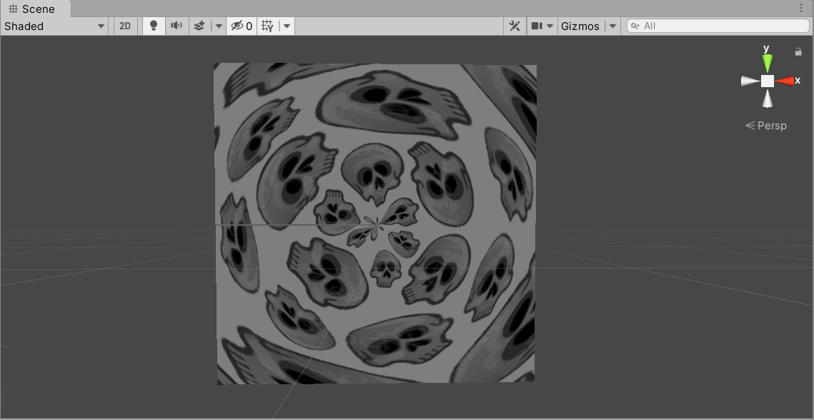
vertex color
Here I would like to say that the model of the polar coordinate animation that the teacher taught was processed in the modeling software in advance. The circle around the patch and the center are all black, so the polar coordinate animation will have a fade-in and fade-out effect when played on the patch: