Article Directory
foreword
1. What is Custom Device?
Custom Device is actually equivalent to a plug-in in Veristand software. This Custom Device plug-in is implemented through Labview programming. It can directly use various functional modules of Labview, and can quickly connect NI-control cards and other Carsim and simulink models for data interaction. However, it needs a certain amount of Labview experience to get started.
2. How to make a Custom Device?
Use Labview's Custom Device Template Tool.vi to create a template project, then compile and generate a library file, and then put the library file in the specified Veristand calling path.
1. Preparation
1.1 Software environment
Labview 2020、Veristand 2020
1.2 Hardware environment
NI-PXIe8880 real-time machine, switch
1.3 Clear mission
1.3.1 Make a Custom Device for TCP reading and writing:
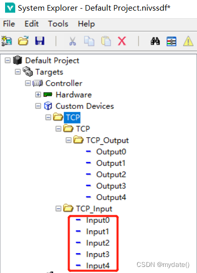
1) Create 5 input variables for writing TCP data;
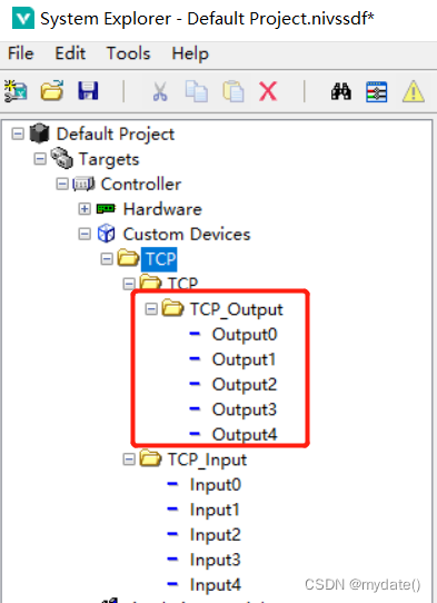
2) Create 5 output variables for reading TCP data; 3) Create variables
(IP and port number) in the Main page.vi; 4) Customize the
IP address and port number for communication in the configuration panel; 5)
Write the data of the input variables into TCP, and output the read TCP data to the output variables;
2. Introduction to the development module
2.1 Create a Custom device template project
2.1.1 Find Custom Device Template Tool.vi
Path:
Labview installation path \vi.lib\NI VeriStand\Custom Device Tools\Custom Device Template Tool\Custom Device Template Tool.vi
举例:
D:\National Instruments\LabVIEW 2020\vi.lib\NI VeriStand\Custom Device Tools\Custom Device Template Tool\Custom Device Template Tool.vi
2.1.2 Create a Custom Device programming template
First open the Custom Device Template Tool.vi
1) Select the save path of the programming template;
2) Enter the name of the template;
3) Run the Labview program;
After running the program, the template will be generated under the template saving path, and the template will be opened automatically

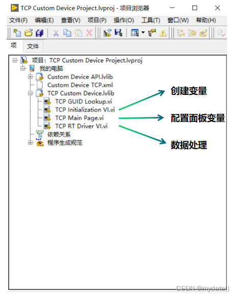
2.2 Custom device template vi function introduction
Custom Device mainly uses the following three template vis, and other VIs of Labview are used;
1) TCP Initialization VI.vi: Create input and output variables, panel variables, etc.;
2) TCP Main Page.vi: Configure panel variables, used to update the value of panel variables;
3) TCP RT Driver VI.vi: Get the value of panel variables, and process the values of input and output variables;
2.3 Introduction to other Vis of Labview
2.3.1 Veristand programming Vi position
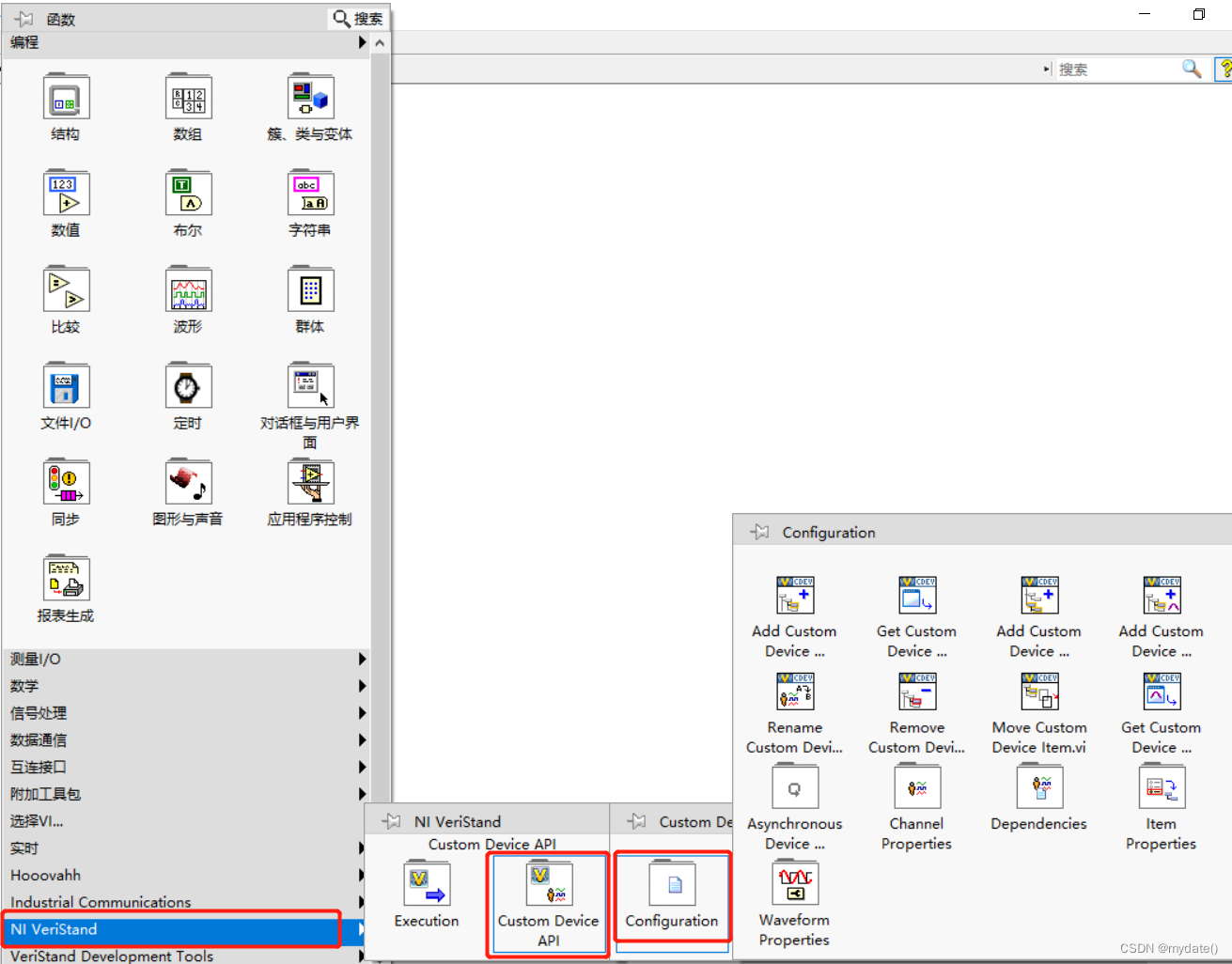
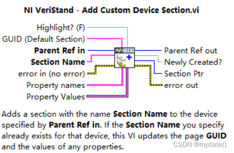
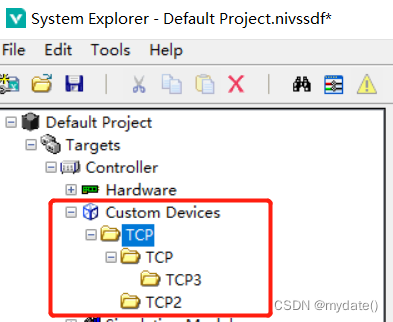
2.3.1 Add Custom Device Section.vi
Add Custom Device Section.vi is used to create a custom device option;
Add Custom Device Section.vi programming case:
we open the TCP Initialization VI.vi in the programming template for programming:
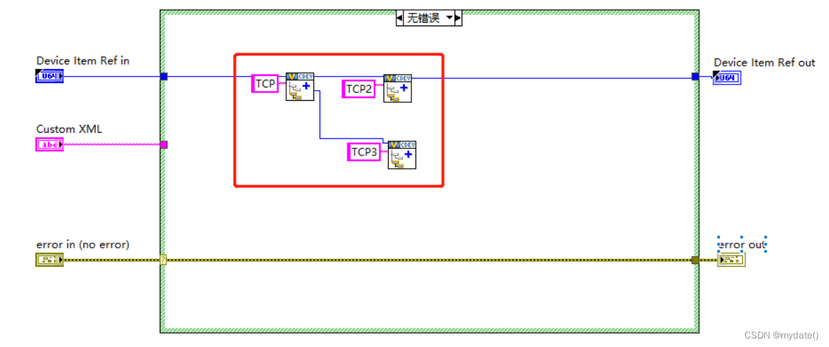
Add Custom Device Section.vi case effect:
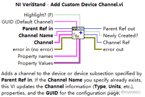
2.3.2 Add Custom Device Channel.vi
Add Custom Device Channel.vi is used to create an input and output variable
Add Custom Device Channel.vi programming case:
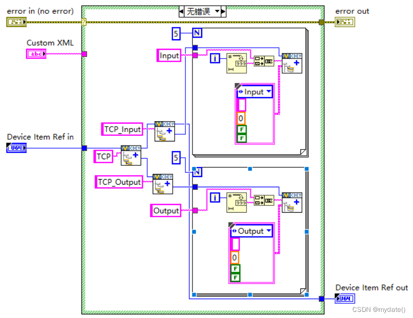
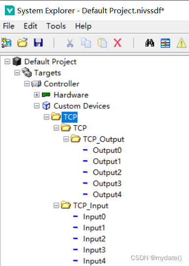
Add Custom Device Channel.vi programming effect:
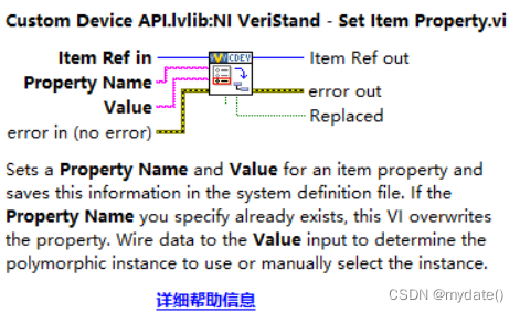
2.3.3 Set Item Property.vi
Set Item Property.vi is used to create the variables of the panel in TCP Main Page.vi and assign initial values;
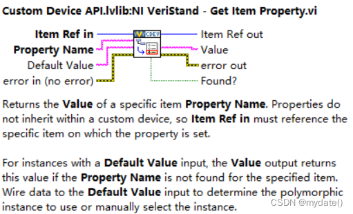
2.3.4 Get Item Property.vi
Get Item Property.vi is used to get the value of the variables of the panel in TCP Main Page.vi;
Three, TCP data sending and receiving case
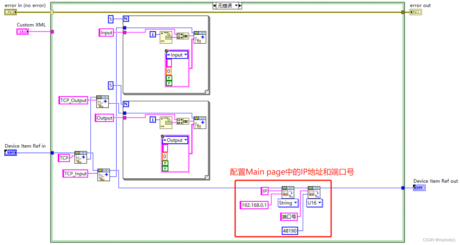
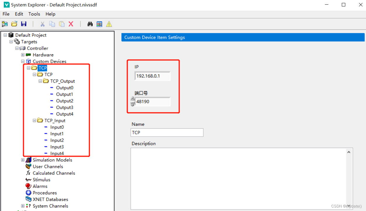
1) Create 5 input variables for writing TCP data (implemented in TCP Initialization VI.vi); 2) Create
5 output variables for reading TCP data (implemented in TCP Initialization VI.vi); 3) Create IP
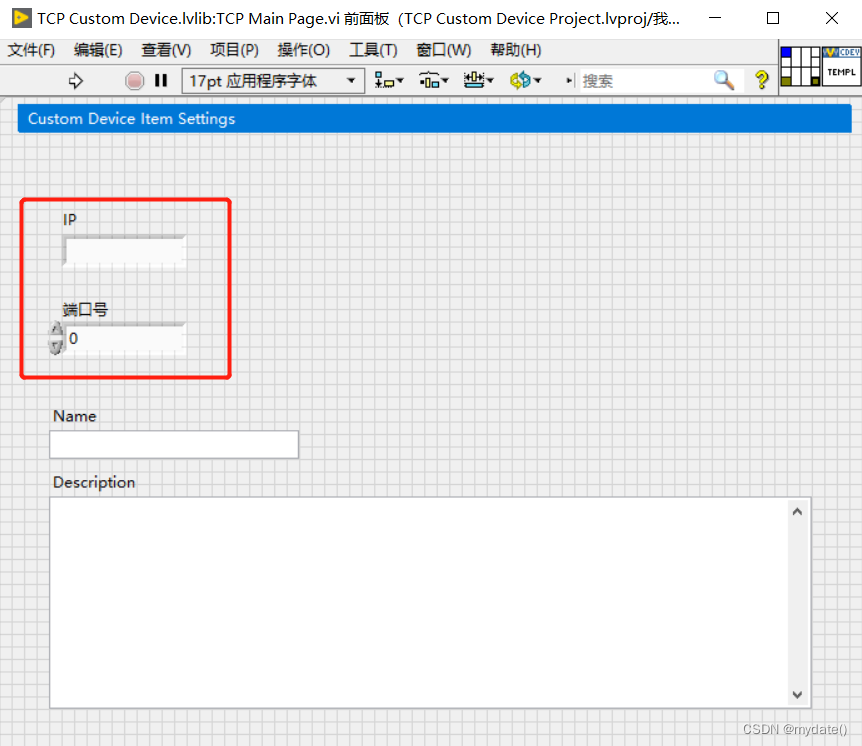
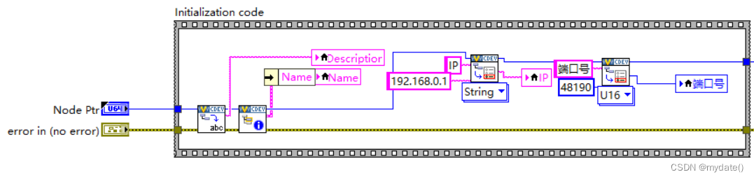
and port number variables in Main page.vi (implemented in TCP Initialization VI.vi); TCP Main Page.vi); ① First open the Main page.vi, add a string control named IP and a numerical control named port number, as shown in the red part of the figure below; ② Set the initial value of IP and port number; get the value of IP and port number through Get Item Property.vi and assign it to the corresponding
panel control ;
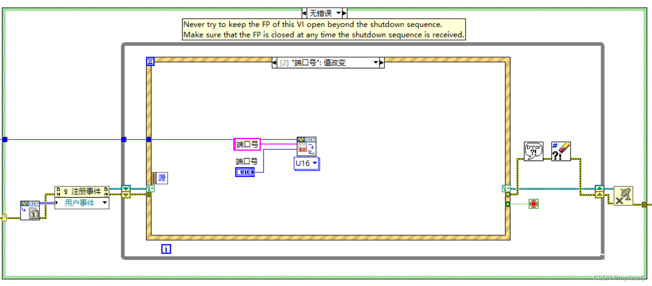
③ Enter the block diagram part, add the event when the IP value is updated and the event when the port number is updated. When the control value changes, the control value can be updated so that we can get the latest value in TCP RT Driver VI.vi; IP value update event: port number value update
event
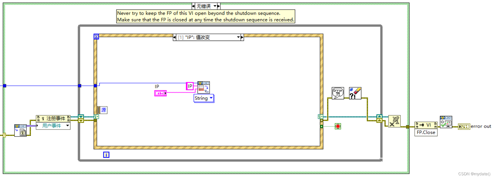
:
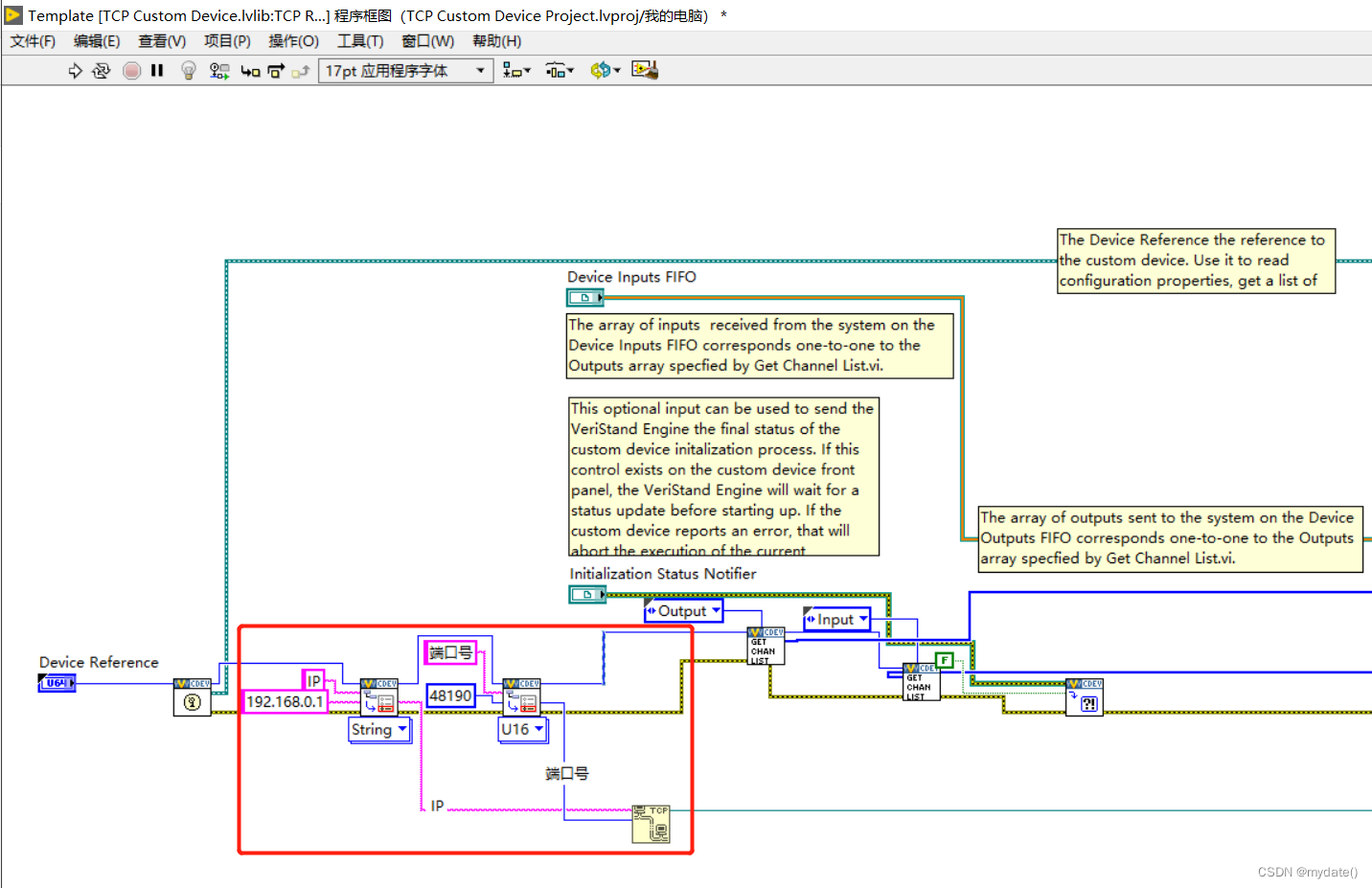
5) Input the input variable data into TCP, and output the read TCP data to the output variable (implemented in TCP RT Driver VI.vi); ① Open TCP RT Driver VI.vi, use Get Item Property.vi to get the IP and port number values on the Main page panel, and open the TCP connection; (The figure below is the leftmost program part of TCP RT Driver VI.vi) ② Get the values of 5 input variables Input, and write them into TCP; the red mark 1 in the figure below indicates The one-dimensional array values obtained from 5 input variables are arranged in the array according to the values of Input0-
Input4, and then we convert the values of the input variables into strings and input them into TCP, as shown in the red label 2 in
the
figure below ;

Note: Get the values of the 5 input variables in the figure below, which are obtained through RT FIFO Read;
③ Fill in the data read from TCP into the 5 output variables; the
red label 2 in the figure below is to convert the data read into the TCP into a numerical array** containing 5 elements (the 5 data are placed in a one-dimensional array in turn), and then output to Output0 - Output4** sequentially through RT FIFO Write, as shown in the red label 1 in the following figure; Note: the numerical array is output to the 5 output variables in the figure below through RT FIFO Write

;
4. Program compilation and application
4.1 Program compilation
Compile
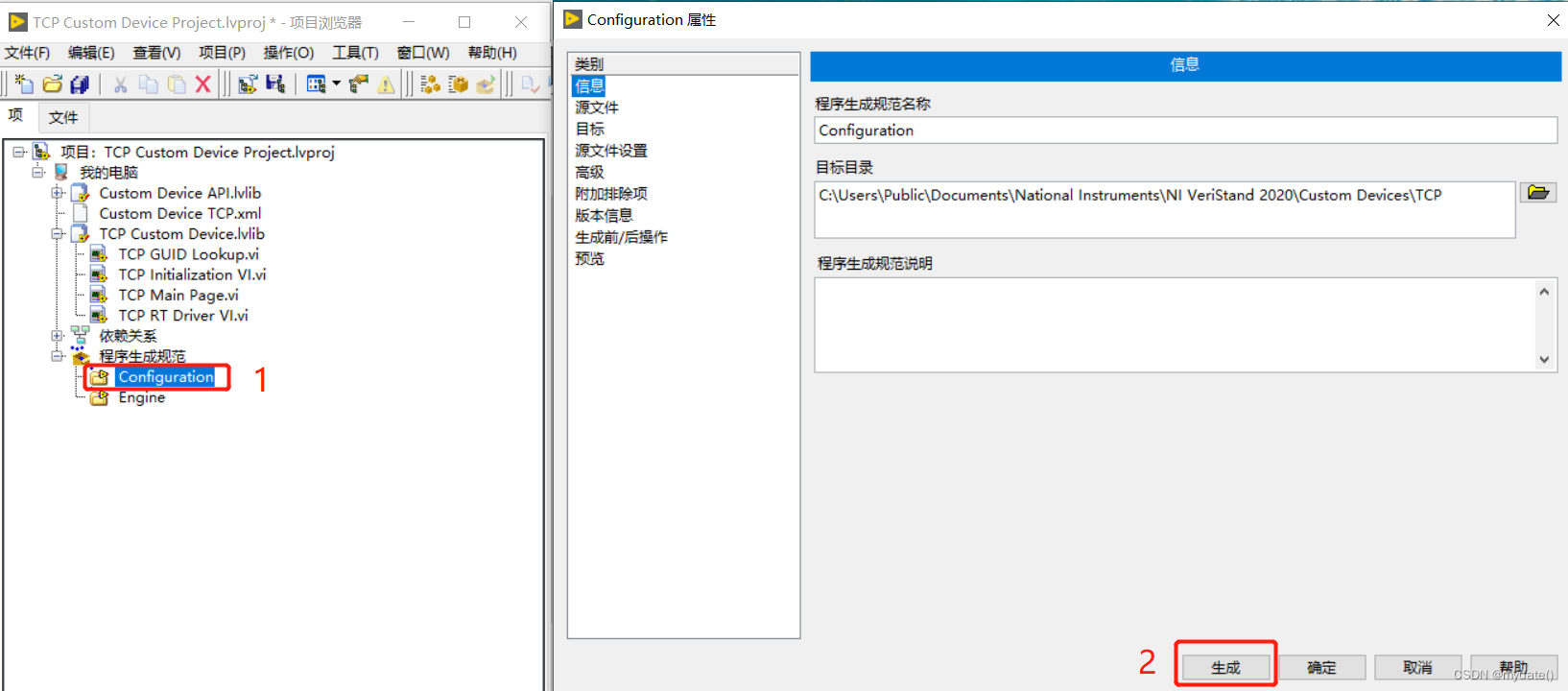
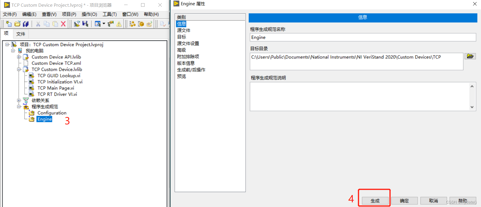
Generate compiled files
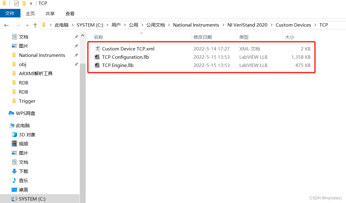
4.2 Call TCP Custom Device
Enter Veristand, right-click Custom Device to automatically obtain the TCP Custom Device under the path, and select it;
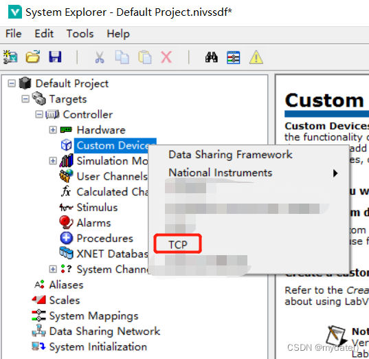
the effect is as follows:
4.3 Use of input and output variables
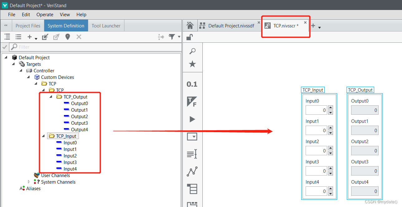
In summary, the production of Custom Device is completed;