Aligot: Cryptographic Function Identification in Obfuscated Binary Programs
Joan Calvet University of Lorraine, LORIA Nancy, France
José M. Fernandez École Polytechnique Montreal, Canada
Jean-Yves Marion University of Lorraine, LORIA Nancy, France
Analyzing encryption implementations has important applications, especially for malware analysis, which are components of the malware payload and the decompression code that decrypts that payload. These implementations are usually based on well-known encryption functions, the descriptions of which are publicly available. Although the Malware analysis can be very useful, but since these cryptographic primitives are often obfuscated, it can be difficult to identify them. Static analysis is usually ineffective, however cryptographic function implementations usually preserve the original function input/output relationships. In this paper , the authors propose a tool that exploits this fact to identify cryptographic functions in obfuscated programs by retrieving their I/O parameters in an implementation-independent manner and comparing them with known cryptographic functions.
In experimental evaluations, the authors successfully identified TEA, RC4, AES, and MD5 encryption functions in synthetic samples protected by a commercial-grade wrapper (AsProtect) and in several obfuscated malware samples (Sality, Waledac, Storm Worm, and SilentBanker) . Furthermore, our tool is able to identify basic operations in asymmetric ciphers such as RSA.
In a word: Identify cryptographic primitives in obfuscated binary programs based on their I/O relationships.
introduction
Most existing tools for cryptographic function identification in binary programs, such as KANAL [33], DRACA [15] or Signsrch [4], are based on static analysis of the identification of code features, such as specific constant values or machine Language instructions, these features are usually present in normal implementations of recognized primitives. However, these tools are mostly ineffective at obfuscating programs that are deliberately designed to be difficult to analyze, thus hiding static symbols that could reveal the presence of known cryptographic functions. Therefore, simple static analysis identification of cryptographic functions is not suitable for such programs.
In contrast to this approach, we here present a method and tool, called Aligot, for identifying cryptographic functions and retrieving their parameters in a manner that is largely independent of the actual implementation. Our solution exploits the specific input-output (I/O) relationship of cryptographic functions. In general, F 1 ( K , C ) = C ′ \mathcal{F}_1(K, C)=C^{\prime}F1(K,C)=C' Denotes encryption functionF 1 \mathcal{F}_1F1Enter the secret key KKK and ciphertextCCAfter C , get the plaintext C'C'C′ , then you can use( ( K , C ) , C ′ ) ((K, C), C')((K,C),C′ )to identifyF 1 \mathcal{F}_1F1.Therefore
, if we in program PPA value KKis observed during a particular execution of PK andCCC is used to generate the valueC'C'C′ , then we can conclude thatPPP realizes F 1 \mathcal{F}_1during this particular executionF1. Of course, not all execution paths of P can realize F 1 \mathcal{F}_1F1, but identifying which potential paths are relevant is a separate reverse engineering problem.
Aligot was built and tested against other encryption detection tools with obfuscated implementations of TEA, RC4, AES, MD5 and RSA encryption functions. Test cases include homemade obfuscators (used for benchmarking), programs obfuscated using commercial packers (AsProtect), and existing malware (Storm, SilentBanker, Sality, Waledac). Aligot significantly outperforms all other tools on all tested cryptographic functions and samples (synthetic and malware).
Program summary
One I/O pair is sufficient to identify most cryptographic functions. We leverage this observation to identify them among obfuscated programs through the following three-step process:
(1) Collect an execution trace of the target program. Our recognition techniques require accurate values of what the program is doing during execution. Dynamic analysis is therefore particularly suitable, execution trajectories thus constituting the problem input.
(2) Extract the encrypted code with I/O parameters from the execution trace. We use specific definitions of loops to build abstractions suitable for encrypted code detection in obfuscated programs. Second, we analyzed the data flow between rounds in order to group data participating in the same encryption implementation, since there are multi-round encryption functions.
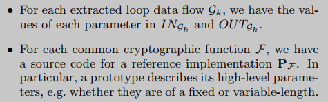
(3) Comparison with known cryptographic functions. Each extracted cyclic data stream is compared against a set of cryptographic reference implementations. If one of the implementations produces the same output as the cyclic data stream when executed on the same input, then it can be concluded that they implement the same cryptographic function.
Execution trace collection
In this work, we only focus on the Windows/x86 platform. Among all available tracing tools in this environment, we chose Pin, a dynamic binary detection framework supported by Intel [17], mainly because of its ease of use and ability to handle self-modifying code, which is a common feature in obfuscated programs. A common technique. While we won't describe the tracer implementation, we do need to introduce a formal notion of execution tracing as the basis for the rest of our reasoning about loops. Execution traces visually represent the sequence of actions a program takes while it is running on the system. At each step, we collect what we call dynamic instructions. A dynamic directive D is a tuple consisting of the following elements:
- Memory address A[D]
- Machine instruction I[D] executed at A[D]
- I[D] memory read/write address RA [ D ] R_A[D]RA[D], W A [ D ] W_A[D] WA[D]
- I[D] register read and write address RR [ D ] R_R[D]RR[D], W R [ D ] W_R[D] WR[D]
Execution Trajectory TTT is a finite sequence of dynamic instructionsD 1 D_1D1; … ; D n D_n Dn. In the remainder of this article, we will denote the machine instruction set as X86 X86X 86 , denote the set of execution traces as TRACE. And, given T∈ \in∈ TRACE, defineT / Ins T_{/Ins}T/InsIt is a machine instruction sequence, that is, T / In ns = I 1 ; . . . ; I n T_{/Ins} = I_1; ...; I_nT/Ins=I1;...;Inwhere ∀ k ∈ [ 1 , n ] \forall k \in [1, n]∀k∈[1,n], I [ D k ] = I k I[D_k] = I_k I[Dk]=Ik. In practice, we also collect the exact value of each data access made by dynamic instructions (in memory or registers).
cycle extraction
When analyzing a binary program, it is often possible to divide the code into functions. But this notion of a function is just a heuristic based on compiler features (calling convention, prologue and epilogue code, etc.), making it unreliable in obfuscated programs. So we build a specific abstraction for encrypted code in a loop-based obfuscation program. In the following, we first introduce some existing loop definitions, and then give our definition and describe the related recognition algorithm.
Cryptographic functions typically apply the same processing to a set of data in an iterative fashion, making loops a very frequent construct in their implementations. It is in these loops that the core cryptographic operations take place and manipulate cryptographic I/O parameters. On the other hand, loops exist in many different types of algorithms, not just encryption algorithms. Therefore, we need a concept of refining loops that focus on encrypted codes. These two consider two specific problems:
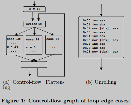
For example, Figure 1(a) demonstrates an obfuscation technique called control flow flattening. Sequential code is converted to a loop, implementing a portion of the original code in each iteration. Therefore, different logic is executed each time: in a cryptographic context, should it be considered a loop?
Second, Figure 1(b) demonstrates a classic compiler optimization technique called unrolling, which can also be used as A means of confusion. A sequence of three instructions repeated three times without any successor: should it be considered a loop in a cryptographic context?
Three existing loop definitions:
(1) Natural loop: A definition commonly used in static program analysis. A back-edge is defined in a program's control flow graph (CFG) as an edge between a node and one of its dominant nodes. Thus, a cycle is identified by a back edge, and applying this definition on a CFG would identify Figure 1(a) as a cycle, but Figure 1(b) would not.
(2) Address-centered loop: A loop is identified by a specific memory address (called the target address), where a set of reverse branch instructions is jumped. In other words, several back edges can correspond to the same loop, which is then identified by the target address. However, this definition also treats Figure 1(a) as a cycle, Figure 1(b) does not.
(3) Instruction-centralized loops: Kobayashi defines a loop on an execution trajectory as the repetition of a machine instruction sequence [14]. By this simple definition, Figure 1(a) is not considered a cycle, while Figure 1(b) is.
We focus on loops because cryptographic code typically uses them to apply the same processing to I/O parameters. Following this idea, Figure 1(a) should not be considered as a cycle because different logic is executed in each iteration, instead Figure 1(b) should be. We therefore choose the Kobayashi method as our starting point: we identify a loop through a repeating sequence of machine instructions, called its body. Therefore, the body of the loop in Figure 1(b) consists of three instructions inc eax, inc ebx and mov [ebx], eax. During execution, the same loop can run several times, each repeating the body a different number of times. We refer to a particular run as an instance of a loop. We also take into account that the last iteration may be incomplete: the loop instance does not necessarily terminate at the exact end of its body.
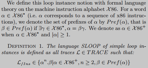
According to the formal language to define the loop instance, the loop instance is n α \alphaα followed byβ \betaβ (ieα \alphaα prefix sequence), where n>=2,α \alphaα isX 86 \mathcal{X}86Instruction sequence of the X86 instruction set.
We also need to consider nested loops. Figure 2(a) is a common case. Block B forms the body of the inner loop, with a different number of iterations for each outer loop iteration (see Figure 2(B)). Therefore, if we apply Definition 1 directly on the execution trace, the outer loop will not be recognized as a loop. Still, it complies with our circular principle: applying the same treatment repeatedly.
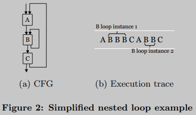
Actually, abstracting each loop instance and recursively applying Definition 1 to solve this problem is enough. Every time a loop instance is detected, we replace its code with the loop identifier from the execution trace. This identifier represents the loop associated with the instance. In other words, we replace every instance of the same loop with the same identifier.
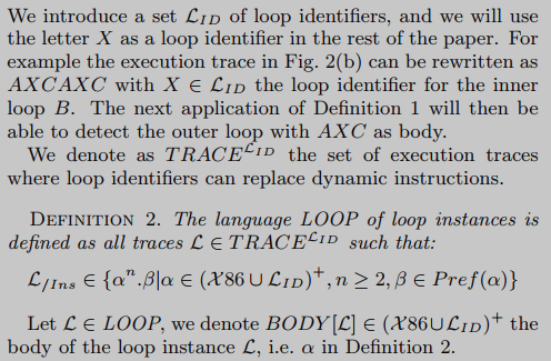
L \mathcal{L}L is an instance of a loop, BODY[L \mathcal{L}L ] is the body of the cycle, and the instance of the cycle can be formalized as nX 86 \mathcal{X}86X86 instruction set and loop identifierLID \mathcal{L}_{ID }LIDThe sequence α \alphaα , continue with the partα \alphaThe prefix of α , ieβ \betab .
Based on the above two definitions, a loop detection algorithm can be constructed with a time complexity of O( m 2 m^2m2 ), m is the size of the execution trace.
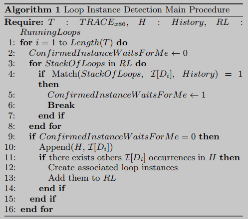
The LOOP recognition algorithm processes the machine instructions from the execution trace one by one and stores them at the end of a list-like structure called history. Common situations are shown in Figure 3(A): instruction I 1 ; I 2 ; I 1 ; I 3 I_1;I_2;I_1;I_3I1;I2;I1;I3It has been recorded in history, and the machine instruction currently processed is I 1 I_1I1. So this instruction appears twice in history. I 1 I_1 in historyI1Each occurrence of corresponds to the start of a possible loop instance. In the first case the subject is α = I 1 ; I 2 ; I 1 ; I 3 α = I_1;I_2;I_1;I_3a=I1;I2;I1;I3, while the second is α = I 1 ; I 3 α = I_1;I_3a=I1;I3. Therefore, the algorithm creates two loop instances named L 1 \mathcal{L}_1L1和L 2 \mathcal{L}_2L2, each loop instance has a pointer to the expected next instruction, L 1 \mathcal{L}_1L1Because I 2 I_2I2, L 2 \mathcal{L}_2L2Because I 3 I_3I3(See Figure 3(b)).
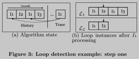
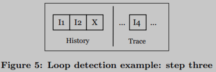
Suppose the next machine instruction is I 4 I_4I4. Then, remove wait I 1 I_1 from the running loop instanceI1的L 2 \mathcal{L}_2L2And register (circular identifier). with its loop identifier X \mathcal{X}X replaces its code, and in doing so allows detection of an outer loop, the number of L2 iterations is independent of each outer loop iteration.
Loop input and output parameters
Loops allow extracting possible cryptographic codes from execution traces, but our ultimate goal is to collect cryptographic parameters. In this section, we introduce the concept of a loop instance parameters and the algorithm to extract these parameters from the execution trace.
Loop instance parameters are the low-level counterparts of high-level implementation parameters (referred to as high-level parameters in the rest of this article). The bytes read or written in the execution trace form our starting point, for the loop instance L we define its parameters by combining the following three necessary conditions:
- The bytes belonging to the parameters of the same L are either adjacent in memory or both in the same register. (This condition alone would tend to group multiple high-level parameters in the same parameter. In fact, different high-level parameters can be adjacent in memory, which is often the case on the stack. But this overapproximation would makes the final comparison stage very complicated; thus the following conditions need to be introduced.
- Bytes belonging to the same parameter of L are manipulated in the same way (read or write) by the same instruction in BODY [L]. (Actually, specific instructions in BODY[L] can operate on different bytes per iteration, but these data tend to have the same effect (especially because of our strict loop definition).
- Finally, bytes belonging to L's input parameters have been read that were not previously written to by L's code, and bytes belonging to L's output parameters have been written to by L's code.
To collect these parameters, we define concrete variables as simple byte arrays starting at a specific memory address. For brevity, only an overview of the parameter collection algorithm is now given.
The algorithm first groups bytes into concrete variables using the first two necessary conditions. Then, by applying a third condition, we divide the concrete variables into two groups, input and output parameters (the same concrete variable can be in both groups).
In the second step, the algorithm associates a fixed value with each previously defined concrete variable. The trace engine collects values for each data access. We use the following two rules to set parameter values: (1) provide its value the first time an input parameter is read, and (2) provide its value the last time an output parameter is written.
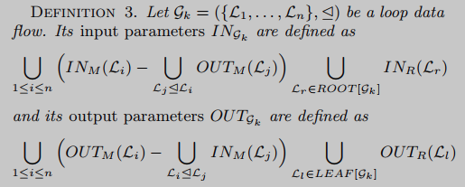
Finally, for each loop instance LLL , the algorithm returns:INM ( L ) IN_M(L)INM(L)和 I N R ( L ) IN_R(L) INR( L ) contains input parameters in memory and registers, respectively,OUTM ( L ) OUT_M(L)OUTM(L)和 O U T R ( L ) OUT_R(L) OUTR( L ) contains output parameters.
The algorithm execution complexity is O(m), where m is the trace size. (Refer to the source code of the paper for the specific algorithm implementation
In order to facilitate the understanding of the previous definition, we give a simple artificial example here. Figure 6 shows an assembly language implementation of a one-time pad cipher, performing a bitwise XOR operation between the input text and a key of the same length.

To decrypt 8-byte text 0xCAFEBABECAFEBABE, we apply this code to a program P that uses an 8-byte key 0xDEADBEEFDEADBEEF. In order to identify cryptographic functions in P with the method proposed in this paper, we need to collect two input values and the associated output results, assuming 0x1453045114530451. The loop parameters are extracted by the above algorithm, which we represent as a parameter graph as shown in Figure 7. Password parameters successfully extracted: 402000:8 and 402008:8 as input and 402000:8 as output. On the other hand, we also collected parameters for the values associated with this particular implementation: (i) eax:4, ebx:4, esp:4, containing memory addresses, (ii) ecx:4, containing counter values, ( iii) 12FFC0:4, corresponding to local variables initialized before the loop (SIZETODECRYPT), and (iv) edx:4, an intermediate store.

cyclic data flow
So far, we have considered every possible encryption implementation to contain a cycle. However, an encryption function can actually consist of several non-nested loops, such as RC4. Therefore, the loop abstraction itself is not enough to fully capture them. To address this, we use dataflows to group loop instances participating in the same encryption implementation.
We define the data flow between loop instances in a similar way to a def-use chain: if L1 produces an output parameter and L2 uses it as an input parameter, two loop instances L1 and L2 are connected. For simplicity, only memory parameters are considered, since register parameters are required for accurate taint tracking in sequential code between loop instances. The actual assumption is that all processing of input and output in memory is handled by loops . (This assumption is a bit strict

In layman's terms, if L i ⊴ L j \mathcal{L}_i \unlhd \mathcal{L}_jLi⊴LjThen it means cycle L i L_iLiThe output will be as L j L_jLj(partial) input of .
Each of these connected slices represents an abstraction, similar to a function in a normal binary program. Therefore, each G k G_kGkis a candidate cryptographic function implementation, which will then be tested against known implementations. Using the standard graph algorithm to reconstruct the loop data flow graph, for each pair of loops L i L_i detectedLiand L j L_jLjTests for a binary relationship, and detects its connected components. In the remainder of this paper, connected slices of a cyclic dataflow graph will simply be referred to as cyclic dataflows.
In the case of combinations between different cryptographic functions, i.e. the output of one function is used as the input of another function, they will be grouped into the same cyclic data stream. One solution is to consider every possible subgraph in a cyclic dataflow graph. For example ( { L 1 , L 2 , L 3 } , ⊴ ) (\{L_1,L_2,L_3\}, \unlhd)({
L1,L2,L3},⊴ ) graphGGG , the algorithm will detect{ L 1 , L 2 , L 3 } \{L_1,L_2,L_3\}{
L1,L2,L3} ,{ L 1 , L 2 } \{L_1,L_2\}{
L1,L2} ,{ L 2 , L 3 } \{L_2,L_3\}{
L2,L3} ,{ L 1 } \{L_1\}{
L1} ,{ L 2 } \{L_2\}{
L2} ,{ L 3 } \{L_3\}{
L3} , the combination of each loop.
The cyclic data flow constitutes our cryptographic implementation model, and our ultimate goal is to extract cryptographic parameters. We define loop dataflow parameters as in-memory loop instance parameters that are not used for internal dataflow. Regarding the register parameters, for simplicity, we take the input registers of the root loop instance and the output registers of the leaf loop instance. The values of these parameters are collected during loop instance parameter extraction. There is now a model that extracts possible cryptographic implementations from execution traces and collects their parameters. We can now identify cryptographic functions.
Compare
The final step in the identification technique is to compare the cyclic data stream to an encrypted reference implementation. We consider two different inputs:
The task of the comparison algorithm is to check ING k IN_{G_k}INGk和 O U T G k OUT_{G_k} OUTGkIs the relation of P_{\mathcal{F}} in the cryptographic function instance PF P_{\mathcal{F}}PFcan also remain unchanged. Before introducing the algorithm, it is necessary to state the difficulties encountered in designing the algorithm. The authors here use publicly available source code as a reference implementation. Therefore, the level of abstraction differs between the parameters extracted from the execution trace and those defined in the high-level source code.
(1) Parameter type. Because what we extracted with the circular dataflow were the low-level arguments, namely contiguous memory addresses and registers, it wasn't obvious how to convert them back to the high-level types implemented by the function reference. In fact, this can lead to artificial mismatches in comparisons, where the same value is represented differently. That's why we chose to use the parameter's reference implementation at the lowest possible level of abstraction (i.e. primitive values).
(2) The order of the parameters. Advanced implementations declare parameters in a specific order, but cyclic dataflow parameters have no order. Therefore, we have to test all possible sequences.
(3) Parameter segmentation. The same high-level parameter can be split into several cyclic dataflow parameters, for example, when it is passed by register but cannot fit in only one of them. Therefore, cyclic data flow parameter values must be combined to construct advanced parameter values. In other words, the mapping between cyclic dataflow parameters and their higher-level counterparts is not 1-to-1, but n-to-1.
(4) Number of parameters. The cyclic data flow parameter captures not only encryption parameters, but also implementation-dependent parameters. Therefore, some cyclic dataflow parameters will not have matching advanced parameters.
Algorithm implementation
(1) Generation of all possible I/O values: Generate all combinations of all possible lengths.
(2) Input parameter mapping: For each password reference implementation PF P_FPF, the algorithm chooses for each high-level parameter its possible value among the parameters generated in the previous step. In particular, for fixed-length arguments, only values with the correct length are chosen.
(3) Comparison: Program PF P_FPFExecutes on every possible combination of its chosen input values. If at some point, the generated value is in the set of possible output values generated in step 1, then it is successful. If not, the algorithm iterates until all combinations have been tested.
experiment
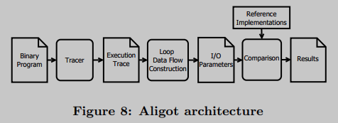
The author builds a toolset called Aligot, which implements the whole recognition process, as shown in Figure 8. The tool consists of about 2000 lines of Python code and 600 lines of C++ code for the tracking engine.
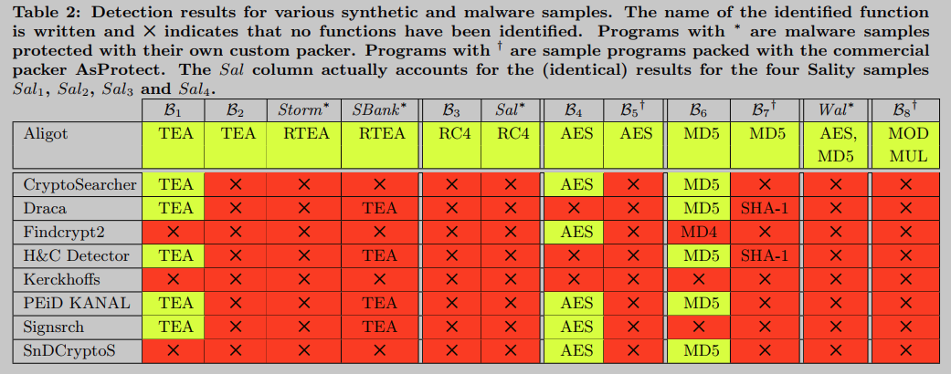
It is worth mentioning that we consider the possibility that some implementations of encryption algorithms that use fixed constants may use different values of these constants (without affecting their security) to avoid detection. To explore this possibility, we tested Aligot's TEA implementation with modified delta constant values. Aligot is still able to detect these modified TEA implementations due to the use of a parameterized reference implementation TEA, where the delta constant becomes an input parameter. The failure of all other tools to do this seems to confirm that their detection of TEA is based solely on the identification of standard delta constant values.

The implementation of Aligot only proves the feasibility of the method, and the performance needs to be optimized.
(For other detailed experimental instructions, see paper
limit
(1) First, like other dynamic analysis tools, Aligot can only identify code that is actually executed at runtime. Determining which potential pathways are relevant for analysis and should be 'feed' to such a tool is a separate research question.
(2) Second, Aligot's recognition capabilities are limited to those functions for which we have a reference implementation.
(3) Despite the experimental results presented in this paper, the paper does not claim that the cyclic data flow model captures every possible obfuscated implementation of cryptographic functions. In fact, computer program analysis is inherently undecidable, as stated by Rice's theorem [13], and this theoretical impossibility is particularly relevant in confusing adversarial games. In the given example, the malware author could simply implement the encryption function with a loop that does not meet our definition.
Summarize
Related Works
[4] L. Auriemma. Signsrch tool. http://aluigi.altervista.org/mytoolz.htm.
[13] J. Hopcroft, R. Motwani, and J. Ullman. Introduction to automata theory, languages, and computation. Addison-Wesley, 2007.
[15] I. O. Levin. Draft crypto analyzer (draca). http://www.literatecode.com/draca.
[17] C. Luk, R. Cohn, R. Muth, H. Patil, A. Klauser, G. Lowney, S. Wallace, V. Reddi, and K. Hazelwood. Pin: building customized program analysis tools with dynamic instrumentation. ACM SIGPLAN Notices, 40:190-200, 2005.
[33] PEiD Krypto Analyzer (kanal). http://www.peid.info.
Insights
(1) Consider all parameter combinations. Here, because the abstraction level is inconsistent, the parameters of the cycle can be verified by blasting.
(2) In essence, the method in this paper is to stay at the level of considering the input-output relationship, which is a very naive idea. Moreover, the assumption made is that the core functions of the default encryption functions are all completed by loops, which is not very helpful for generalized function detection and cannot be anti-obfuscated.
(3) Use history or trace or execution status information to support function detection tasks.