Article directory
foreword
In ROS, robot modeling and simulation is a very important part. Modeling and simulation allows developers to develop and test without using actual robots, saving time and money. ROS uses URDF (Unified Robot Description Format) as a robot modeling language, and provides some tools to create and edit URDF files, such as RViz and Gazebo.
URDF file: URDF file describes the physical characteristics of the robot, including links and joints, as well as sensors and actuators, etc. Developers can use URDF files to create robot models and run them in a simulation environment.
Gazebo Simulator: Gazebo is a powerful tool for robot simulation that simulates the physics and environmental conditions of a robot. Gazebo supports ROS and can be integrated with ROS, allowing developers to use nodes and messages in ROS to control robot models.
RViz visualization tool: RViz is a visualization tool for ROS that can be used to visualize robot models, sensor data, and control output. Developers can use RViz to debug robot models and perform visual analysis.
ROS controller: ROS provides some controllers, such as joint controller and force controller, which can be used to control the joints and actuators of the robot model.
By using the tools and techniques described above, developers can easily create and simulate robot models for development and testing. This makes robot application development more efficient, flexible and reliable.
1. URDF modeling
URDF is an XML file format used to describe robot models. URDF (Unified Robot Description Format) It is one of the standard formats used in ROS. URDF contains information such as robot geometry, sensors, joints and links, which can be used to build robot models, simulation and control.
URDF files are usually written with a text editor, but can also be created and edited using a variety of URDF editors and visualization tools. Common editors for URDF include Robotics Toolbox for MATLAB, Blender, SolidWorks, and OpenRAVE, etc.
In ROS, URDF files can be integrated with other ROS tools and programs, such as the ROS controller and the Gazebo simulator. Let's talk about the syntax of URDF in detail
1. Detailed explanation of URDF syntax
a. robot
In order to ensure the integrity of the xml syntax in urdf, the robot tag is used as the root tag, and all link, joint and other tags must be included in the robot tag
<!-- 根标签 -->
<robot name="car_robot">

	<!-- 子级标签 -->

</robot>
In the root tag, the name of the robot model can be set through the name attribute, and other tags are child tags
b. link
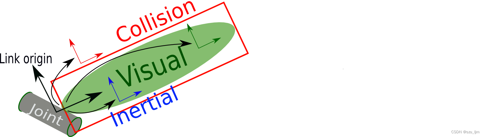
< l i n k > <link> <link> Labels are used to describe the connectors of an object or robot. Each connector has its own coordinate system that can be used to describe the relative position and orientation of the connections. per<link> <link><link> tags must have a unique name, and can contain multiple<visual> <visual><visual>、 < c o l l i s i o n > <collision> <collision>、 < i n e r t i a l > <inertial> <inertial>、 < s e n s o r > <sensor> <sensor> 和 < a u d i o > <audio> <audio> Sub-tabs that describe the properties and characteristics of the connector.
    <!-- 子标签name- - -> 为连杆命名 -->
    <link name="base_link">
        <visual>
            <!-- 子标签geometry- - -> 设置连杆的形状 -->
            <geometry>
                <!-- 子标签box- - ->长方体的长宽高 -->
                <!-- <box size="0.5 0.3 0.1" /> -->
                <!-- 子标签cylinder- - ->圆柱的半径和长度 -->
                <!-- <cylinder radius="0.5" length="0.1" /> -->
                <!-- 子标签sphere- - ->球体的半径-->
                <!-- <sphere radius="0.3" /> -->

            </geometry>
            <!-- 子标签origin - - ->  设置偏移量与欧拉角(3.14=180度 1.57=90度) -->
            <origin xyz="0 0 0" rpy="0 0 0" />
            <!-- 子标签 metrial - - -> 设置材料颜色: r=red g=green b=blue a=alpha -->
            <material name="black">
                <color rgba="0.7 0.5 0 0.5" />
            </material>
            <!-- 子标签collision ---> 连杆的碰撞属性 -->
            <!-- 子标签Inertial ---> 连杆的惯性矩阵 -->
        </visual>
    </link>
c. joint
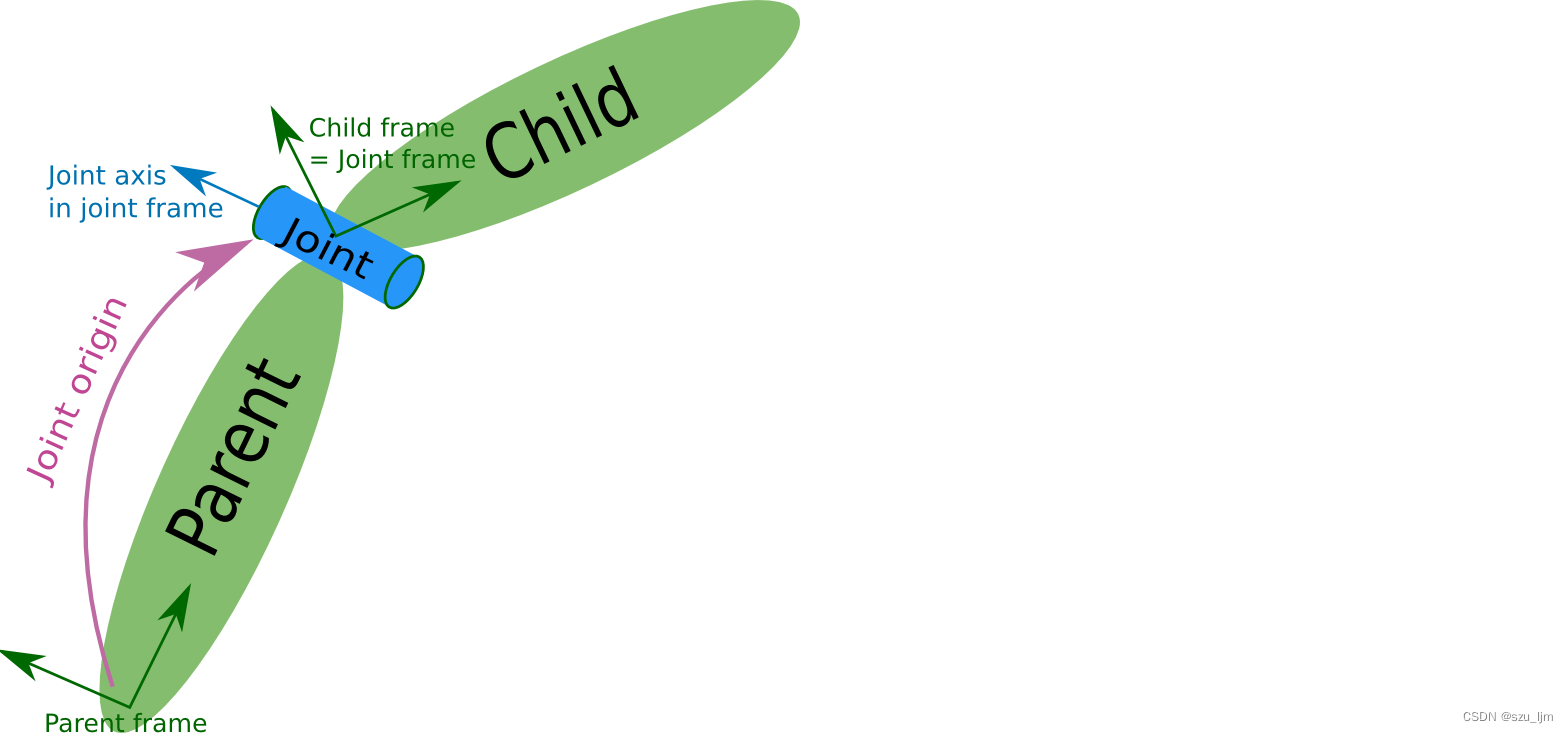
< j o i n t > <joint> <jointThe > tag is used to describe the properties of joints connecting two connectors in the robot model, and is used to describe the kinematics and dynamics of the robot. Each<joint> <joint><joint> Tags must have a unique name, and must explicitly specify the names of the parent and child connectors. In the robot model, multiple<link> <link><link> tags can pass<joint> <joint><joint> Tags are connected together to form a complete robot structure. The combination of connectors and joints can describe the kinematics and dynamics of the robot for robot simulation and control.
<!--
    需求: 创建机器人模型,底盘为长方体,
         在长方体的前面添加一摄像头,
         摄像头可以沿着 Z 轴 360 度旋转

 -->
<robot name="mycar">
    <!-- 底盘 -->
    <link name="base_link">
        <visual>
            <geometry>
                <box size="0.5 0.2 0.1" />
            </geometry>
            <origin xyz="0 0 0" rpy="0 0 0" />
            <material name="blue">
                <color rgba="0 0 1.0 0.5" />
            </material>
        </visual>
    </link>

    <!-- 摄像头 -->
    <link name="camera">
        <visual>
            <geometry>
                <box size="0.02 0.05 0.05" />
            </geometry>
            <origin xyz="0 0 0" rpy="0 0 0" />
            <material name="red">
                <color rgba="1 0 0 0.5" />
            </material>
        </visual>
    </link>

    <!-- 关节 -->
    <!-- 属性name - - -> 为关节命名 -->
    <!-- 属性type - - -> 关节运动形式:continuous旋转关节、revolute旋转关节、prismatic滑动关节、planer平面关节、floating浮动关节、fixed固定关节 -->
    <joint name="camera2baselink" type="continuous">
        <!-- parent link:父级连杆的名字,是这个link在机器人结构树中的名字 -->
        <parent link="base_link"/>
        <!-- child link:子级连杆的名字,是这个link在机器人结构树中的名字 -->
        <child link="camera" />
        <!-- origin:xyz=各轴线上的偏移量 rpy=各轴线上的偏移弧度 -->
        <origin xyz="0.2 0 0.075" rpy="0 0 0" />
        <!-- axis: xyz用于设置围绕哪个关节轴运动 -->
        <axis xyz="0 0 1" />
    </joint>

</robot>
2. URDF robot modeling practice
Next, let's practice URDF robot modeling. We first build a simple robot chassis, plus two driving wheels and a support wheel, so that the robot can move through the motion controller. First, right-click the src directory and select Create Catkin Package, add several dependent packages roscpp, rospy, urdf, xacro, create a new urdf folder, create a new urdf folder inside, and create a model.urdf file inside
<robot name="mycar">
    <!-- 设置 base_footprint  -->
    <link name="base_footprint">
        <visual>
            <geometry>
                <sphere radius="0.001" />
            </geometry>
        </visual>
    </link>
    <!-- 设置 机器人底盘  -->
     <link name="base_link">
        <visual>
            <geometry>
                <cylinder radius="0.1" length="0.08" />
            </geometry>
            <origin xyz="0 0 0" rpy="0 0 0" />
            <material name="yellow">
                <color rgba="0.8 0.3 0.1 0.5" />
            </material>
        </visual>
    </link>
    <!-- 设置 左驱动轮  -->
    <link name="left_wheel">
        <visual>
            <geometry>
                <cylinder radius="0.0325" length="0.015" />
            </geometry>
            <origin xyz="0 0 0" rpy="1.5705 0 0" />
            <material name="black">
                <color rgba="0.0 0.0 0.0 1.0" />
            </material>
        </visual>
	</link>
	<!-- 设置 右驱动轮  -->
    <link name="right_wheel">
        <visual>
            <geometry>
                <cylinder radius="0.0325" length="0.015" />
            </geometry>
            <origin xyz="0 0 0" rpy="1.5705 0 0" />
            <material name="black">
                <color rgba="0.0 0.0 0.0 1.0" />
            </material>
        </visual>
	</link>
	<!-- 设置 后支撑轮  -->
	 <link name="back_wheel">
        <visual>
            <geometry>
                <sphere radius="0.0075" />
            </geometry>
            <origin xyz="0 0 0" rpy="0 0 0" />
            <material name="black">
                <color rgba="0.0 0.0 0.0 1.0" />
            </material>
        </visual>
    </link>

    <!-- 设置 base_footprint与机器人底盘的关节  -->
    <joint name="base_link2base_footprint" type="fixed">
        <parent link="base_footprint" />
        <child link="base_link"/>
        <origin xyz="0 0 0.055" />
    </joint>
     <!-- 设置 左驱动轮与机器人底盘的关节  -->
     <joint name="left_wheel2base_link" type="continuous">
        <parent link="base_link" />
        <child link="left_wheel" />
        <origin xyz="0 0.1 -0.0225" />
        <axis xyz="0 1 0" />
    </joint>
     <!-- 设置 右驱动轮与机器人底盘的关节  -->
	 <joint name="right_wheel2base_link" type="continuous">
        <parent link="base_link" />
        <child link="right_wheel" />
        <origin xyz="0 -0.1 -0.0225" />
        <axis xyz="0 1 0" />
    </joint>
    <!-- 设置 后支撑轮与机器人底盘的关节  -->
    <joint name="back_wheel2base_link" type="continuous">
        <parent link="base_link" />
        <child link="back_wheel" />
        <origin xyz="-0.0925 0 -0.0475" />
        <axis xyz="1 1 1" />
    </joint>
Then create a launch folder under the function package, create a new xxx.launch file, and then modify the following code according to the file path and copy it in
<launch>
    <!-- 将 urdf 文件内容设置进参数服务器 -->
    <param name="robot_description" textfile="$(find my_robot)/urdf/urdf/model.urdf" />

    <!-- 启动 rivz -->
	<node pkg="rviz" type="rviz" name="rviz" />

    <!-- 启动机器人状态和关节状态发布节点 -->
    <node pkg="robot_state_publisher" type="robot_state_publisher" name="robot_state_publisher" />
    <node pkg="joint_state_publisher" type="joint_state_publisher" name="joint_state_publisher" />

    <!-- 启动图形化的控制关节运动节点 -->
    <node pkg="joint_state_publisher_gui" type="joint_state_publisher_gui" name="joint_state_publisher_gui" />

</launch>
Finally, open a terminal and run the following command
roslaunch xxx(功能包) xxx.launch(launch文件)
As long as it is configured in rviz, the robot model can be displayed. The configuration in rviz will be mentioned later
2. Xacro macro optimization
Xacro is an XML-based macro language that can be used to describe the structure and parameters of robot models. xacro files can generate URDF model files by writing simple XML codes. In the case of complex robot models, xacro can reduce code duplication, improve code readability and maintainability, and improve the performance and efficiency of robot models.
1. Detailed Xacro macro syntax
The attribute property is used to encapsulate some fields in URDF, such as: PAI value, car size, wheel radius, and can also be used for arithmetic calculations to set some coordinate offsets
<xacro:property name="xxxx" value="yyyy" />
The Xacro macro definition is similar to the function definition implementation, which can improve the code reuse rate, optimize the code structure, and improve security. It is necessary to fill in the macro name and available parameter list information
<xacro:macro name="宏名称" params="参数列表(多参数之间使用空格分隔)">

    .....

    参数调用格式: ${参数名}

</xacro:macro>
Xacro macro call is similar to function call implementation, you need to fill in the macro name and corresponding parameter value
<xacro:宏名称 参数1=xxx 参数2=xxx/>
The robot is composed of multiple parts, and different parts may be packaged into separate xacro files. Finally, different files are integrated and combined into a complete robot, which can be implemented using file inclusion
<robot name="xxx" xmlns:xacro="http://wiki.ros.org/xacro">
      <xacro:include filename="my_base.xacro" />
      ....
</robot>
2. Xacro modeling practice
Now we use the xacro macro to optimize the actual operation process of URDF modeling. This time we first build the robot chassis, camera, and lidar, and then put these parts together. First, create a new xxx under the same level directory as the xxx.urdf file. urdf.xacro file, then write the xacro file for camera and lidar
<!-- 摄像头相关的 xacro 文件 -->
<robot name="my_camera" xmlns:xacro="http://wiki.ros.org/xacro">
    <!-- 摄像头属性 -->
    <xacro:property name="camera_length" value="0.01" /> <!-- 摄像头长度(x) -->
    <xacro:property name="camera_width" value="0.025" /> <!-- 摄像头宽度(y) -->
    <xacro:property name="camera_height" value="0.025" /> <!-- 摄像头高度(z) -->
    <xacro:property name="camera_x" value="0.08" /> <!-- 摄像头安装的x坐标 -->
    <xacro:property name="camera_y" value="0.0" /> <!-- 摄像头安装的y坐标 -->
    <xacro:property name="camera_z" value="${base_link_length / 2 + camera_height / 2}" /> <!-- 摄像头安装的z坐标:底盘高度 / 2 + 摄像头高度 / 2  -->

    <!-- 摄像头关节以及link -->
    <link name="camera">
        <visual>
            <geometry>
                <box size="${camera_length} ${camera_width} ${camera_height}" />
            </geometry>
            <origin xyz="0.0 0.0 0.0" rpy="0.0 0.0 0.0" />
            <material name="black" />
        </visual>
    </link>

    <joint name="camera2base_link" type="fixed">
        <parent link="base_link" />
        <child link="camera" />
        <origin xyz="${camera_x} ${camera_y} ${camera_z}" />
    </joint>
</robot>
<!--
    小车底盘添加激光雷达
-->
<robot name="my_laser" xmlns:xacro="http://wiki.ros.org/xacro">

    <!-- 激光雷达支架 -->
    <xacro:property name="support_length" value="0.15" /> <!-- 支架长度 -->
    <xacro:property name="support_radius" value="0.01" /> <!-- 支架半径 -->
    <xacro:property name="support_x" value="0.0" /> <!-- 支架安装的x坐标 -->
    <xacro:property name="support_y" value="0.0" /> <!-- 支架安装的y坐标 -->
    <xacro:property name="support_z" value="${base_link_length / 2 + support_length / 2}" /> <!-- 支架安装的z坐标:底盘高度 / 2 + 支架高度 / 2  -->

    <link name="support">
        <visual>
            <geometry>
                <cylinder radius="${support_radius}" length="${support_length}" />
            </geometry>
            <origin xyz="0.0 0.0 0.0" rpy="0.0 0.0 0.0" />
            <material name="red">
                <color rgba="0.8 0.2 0.0 0.8" />
            </material>
        </visual>
    </link>

    <joint name="support2base_link" type="fixed">
        <parent link="base_link" />
        <child link="support" />
        <origin xyz="${support_x} ${support_y} ${support_z}" />
    </joint>


    <!-- 激光雷达属性 -->
    <xacro:property name="laser_length" value="0.05" /> <!-- 激光雷达长度 -->
    <xacro:property name="laser_radius" value="0.03" /> <!-- 激光雷达半径 -->
    <xacro:property name="laser_x" value="0.0" /> <!-- 激光雷达安装的x坐标 -->
    <xacro:property name="laser_y" value="0.0" /> <!-- 激光雷达安装的y坐标 -->
    <xacro:property name="laser_z" value="${support_length / 2 + laser_length / 2}" /> <!-- 激光雷达安装的z坐标:支架高度 / 2 + 激光雷达高度 / 2  -->

    <!-- 激光雷达关节以及link -->
    <link name="laser">
        <visual>
            <geometry>
                <cylinder radius="${laser_radius}" length="${laser_length}" />
            </geometry>
            <origin xyz="0.0 0.0 0.0" rpy="0.0 0.0 0.0" />
            <material name="black" />
        </visual>
    </link>

    <joint name="laser2support" type="fixed">
        <parent link="support" />
        <child link="laser" />
        <origin xyz="${laser_x} ${laser_y} ${laser_z}" />
    </joint>
</robot>
Then write the xacro file of the robot chassis
<!--
    使用 xacro 优化 URDF 版的小车底盘实现:

    实现思路:
    1.将一些常量、变量封装为 xacro:property
      比如:PI 值、小车底盘半径、离地间距、车轮半径、宽度 ....
    2.使用 宏 封装驱动轮以及支撑轮实现,调用相关宏生成驱动轮与支撑轮

-->
<!-- 根标签,必须声明 xmlns:xacro -->
<robot name="my_base" xmlns:xacro="http://www.ros.org/wiki/xacro">
    <!-- 封装变量、常量 -->
    <xacro:property name="PI" value="3.141"/>
    <!-- 宏:黑色设置 -->
    <material name="black">
        <color rgba="0.0 0.0 0.0 1.0" />
    </material>
    <!-- 底盘属性 -->
    <xacro:property name="base_footprint_radius" value="0.001" /> <!-- base_footprint 半径  -->
    <xacro:property name="base_link_radius" value="0.1" /> <!-- base_link 半径 -->
    <xacro:property name="base_link_length" value="0.08" /> <!-- base_link 长 -->
    <xacro:property name="earth_space" value="0.015" /> <!-- 离地间距 -->

    <!-- 底盘 -->
    <link name="base_footprint">
      <visual>
        <geometry>
          <sphere radius="${base_footprint_radius}" />
        </geometry>
      </visual>
    </link>

    <link name="base_link">
      <visual>
        <geometry>
          <cylinder radius="${base_link_radius}" length="${base_link_length}" />
        </geometry>
        <origin xyz="0 0 0" rpy="0 0 0" />
        <material name="yellow">
          <color rgba="0.5 0.3 0.0 0.5" />
        </material>
      </visual>
    </link>

    <joint name="base_link2base_footprint" type="fixed">
      <parent link="base_footprint" />
      <child link="base_link" />
      <origin xyz="0 0 ${earth_space + base_link_length / 2 }" />
    </joint>

    <!-- 驱动轮 -->
    <!-- 驱动轮属性 -->
    <xacro:property name="wheel_radius" value="0.0325" /><!-- 半径 -->
    <xacro:property name="wheel_length" value="0.015" /><!-- 宽度 -->
    <!-- 驱动轮宏实现 -->
    <xacro:macro name="add_wheels" params="name flag">
      <link name="${name}_wheel">
        <visual>
          <geometry>
            <cylinder radius="${wheel_radius}" length="${wheel_length}" />
          </geometry>
          <origin xyz="0.0 0.0 0.0" rpy="${PI / 2} 0.0 0.0" />
          <material name="black" />
        </visual>
      </link>

      <joint name="${name}_wheel2base_link" type="continuous">
        <parent link="base_link" />
        <child link="${name}_wheel" />
        <origin xyz="0 ${flag * base_link_radius} ${-(earth_space + base_link_length / 2 - wheel_radius) }" />
        <axis xyz="0 1 0" />
      </joint>
    </xacro:macro>
    <xacro:add_wheels name="left" flag="1" />
    <xacro:add_wheels name="right" flag="-1" />
    <!-- 支撑轮 -->
    <!-- 支撑轮属性 -->
    <xacro:property name="support_wheel_radius" value="0.0075" /> <!-- 支撑轮半径 -->

    <!-- 支撑轮宏 -->
    <xacro:macro name="add_support_wheel" params="name flag" >
      <link name="${name}_wheel">
        <visual>
            <geometry>
                <sphere radius="${support_wheel_radius}" />
            </geometry>
            <origin xyz="0 0 0" rpy="0 0 0" />
            <material name="black" />
        </visual>
      </link>

      <joint name="${name}_wheel2base_link" type="continuous">
          <parent link="base_link" />
          <child link="${name}_wheel" />
          <origin xyz="${flag * (base_link_radius - support_wheel_radius)} 0 ${-(base_link_length / 2 + earth_space / 2)}" />
          <axis xyz="1 1 1" />
      </joint>
    </xacro:macro>

    <xacro:add_support_wheel name="front" flag="1" />
    <xacro:add_support_wheel name="back" flag="-1" />

</robot>
Then write a my_robot.urdf.xacro file, include the xacro files of the above robot parts, and you can put all the robot parts together
<!-- 组合小车底盘与摄像头与雷达 -->
<robot name="my_car_camera" xmlns:xacro="http://wiki.ros.org/xacro">
    <xacro:include filename="my_base.urdf.xacro" />
    <xacro:include filename="my_camera.urdf.xacro" />
    <xacro:include filename="my_laser.urdf.xacro" />
</robot>
Finally, create a new my_robot.launch file under the launch folder, which is used to load the robot model and start rviz
<launch>
    <param name="robot_description" command="$(find xacro)/xacro $(find demo01_urdf_helloworld)/urdf/xacro/my_robot.urdf.xacro" />

    <node pkg="rviz" type="rviz" name="rviz" />
    <node pkg="joint_state_publisher" type="joint_state_publisher" name="joint_state_publisher" output="screen" />
    <node pkg="robot_state_publisher" type="robot_state_publisher" name="robot_state_publisher" output="screen" />
    <node pkg="joint_state_publisher_gui" type="joint_state_publisher_gui" name="joint_state_publisher_gui" output="screen" />
</launch>
Finally, open the terminal, execute the following command, and configure the RobotModel in rviz to see the robot model
roslaunch xxx(功能包) my_robot.launch(launch文件)
3. Rviz and Gazebo simulation
rviz is a visualization tool in ROS that is used to display information such as the state of the robot, sensor data, and motion planning. It can display 3D models, point clouds, lidar data, images, paths, etc., and can be operated through an interactive interface, such as translation, rotation, zooming, etc. rviz can also communicate with other ROS nodes, such as communicating with robot control nodes, to realize robot motion planning control.
Gazebo is a powerful simulator in ROS for simulating robot motion and sensor data in a virtual environment. It can simulate various types of robots, including mobile robots, humanoid robots, and drones, while supporting multiple sensor types, such as cameras, lidar, and IMUs. In Gazebo, users can create a virtual environment, including terrain, obstacles and objects, etc., and place the robot in it. By controlling the movement of the robot, users can observe the behavior of the robot in the virtual environment, and perform work such as algorithm testing and optimization. Gazebo can also communicate with other ROS nodes, such as communicating with robot control nodes to realize robot motion control.
1. Gazebo integrated URDF modeling grammar basis
The Gazebo simulation environment loads the URDF model file, and requires the use of collision tags, because collision detection is bound to be involved in the simulation environment, and collision provides the basis for collision detection; it is also necessary to provide the use of inertial inertia matrix tags, which mark a certain rigid body of the current robot Part of the inertia matrix is used for some mechanics-related simulation calculations.
When the collision label is set, if the robot's connector is a standard geometric shape, the setting should be consistent with the geometry shape attribute
The setting of the inertia matrix label inertia needs to be dynamically generated in combination with the mass distribution and shape parameters of the connector. The following is the calculation formula of the inertia matrix, JJJ is the moment of inertia,ri r_{i}riis the distance from the mass point to the axis of rotation
J = ∑ miri 2 J = \sum m_{i}r_{i}^{2}J=∑miri2
<!-- 球体惯性矩阵 -->
<!-- Macro for inertia matrix -->
    <xacro:macro name="sphere_inertial_matrix" params="m r">
        <inertial>
            <mass value="${m}" />
            <inertia ixx="${2*m*r*r/5}" ixy="0" ixz="0"
                iyy="${2*m*r*r/5}" iyz="0"
                izz="${2*m*r*r/5}" />
        </inertial>
    </xacro:macro>
<!-- 圆柱惯性矩阵 -->
<xacro:macro name="cylinder_inertial_matrix" params="m r h">
        <inertial>
            <mass value="${m}" />
            <inertia ixx="${m*(3*r*r+h*h)/12}" ixy = "0" ixz = "0"
                iyy="${m*(3*r*r+h*h)/12}" iyz = "0"
                izz="${m*r*r/2}" />
        </inertial>
    </xacro:macro>
<!-- 立方体惯性矩阵 -->
 <xacro:macro name="Box_inertial_matrix" params="m l w h">
       <inertial>
               <mass value="${m}" />
               <inertia ixx="${m*(h*h + l*l)/12}" ixy = "0" ixz = "0"
                   iyy="${m*(w*w + l*l)/12}" iyz= "0"
                   izz="${m*(w*w + h*h)/12}" />
       </inertial>
   </xacro:macro>
In addition to the base_footprint, each rigid body part of the robot needs to set an inertia matrix. The inertia matrix is calculated according to the law of rotation. If the inertia matrix of the rigid body part is defined arbitrarily, it may cause the robot to shake and move in Gazebo. Other places are basically the same as the previous URDF modeling
2. Gazebo integrated URDF practical operation
In order to display the robot model in Gazebo, you need to add collision labels, inertia matrix labels, and color labels to the previous xacro macro file. Other operations are basically the same as before. First, write the xacro file of the robot inertia matrix algorithm.
<robot name="base" xmlns:xacro="http://wiki.ros.org/xacro">
    <!-- Macro for inertia matrix -->
    <xacro:macro name="sphere_inertial_matrix" params="m r">
        <inertial>
            <mass value="${m}" />
            <inertia ixx="${2*m*r*r/5}" ixy="0" ixz="0"
                iyy="${2*m*r*r/5}" iyz="0"
                izz="${2*m*r*r/5}" />
        </inertial>
    </xacro:macro>

    <xacro:macro name="cylinder_inertial_matrix" params="m r h">
        <inertial>
            <mass value="${m}" />
            <inertia ixx="${m*(3*r*r+h*h)/12}" ixy = "0" ixz = "0"
                iyy="${m*(3*r*r+h*h)/12}" iyz = "0"
                izz="${m*r*r/2}" />
        </inertial>
    </xacro:macro>

    <xacro:macro name="Box_inertial_matrix" params="m l w h">
       <inertial>
               <mass value="${m}" />
               <inertia ixx="${m*(h*h + l*l)/12}" ixy = "0" ixz = "0"
                   iyy="${m*(w*w + l*l)/12}" iyz= "0"
                   izz="${m*(w*w + h*h)/12}" />
       </inertial>
   </xacro:macro>
</robot>
Then write the xacro file of the robot chassis
<!--
    使用 xacro 优化 URDF 版的小车底盘实现:

    实现思路:
    1.将一些常量、变量封装为 xacro:property
      比如:PI 值、小车底盘半径、离地间距、车轮半径、宽度 ....
    2.使用 宏 封装驱动轮以及支撑轮实现,调用相关宏生成驱动轮与支撑轮

-->
<!-- 根标签,必须声明 xmlns:xacro -->
<robot name="my_base" xmlns:xacro="http://www.ros.org/wiki/xacro">
    <!-- 封装变量、常量 -->
    <!-- PI 值设置精度需要高一些,否则后续车轮翻转量计算时,可能会出现肉眼不能察觉的车轮倾斜,从而导致模型抖动 -->
    <xacro:property name="PI" value="3.1415926"/>
    <!-- 宏:黑色设置 -->
    <material name="black">
        <color rgba="0.0 0.0 0.0 1.0" />
    </material>
    <!-- 底盘属性 -->
    <xacro:property name="base_footprint_radius" value="0.001" /> <!-- base_footprint 半径  -->
    <xacro:property name="base_link_radius" value="0.1" /> <!-- base_link 半径 -->
    <xacro:property name="base_link_length" value="0.08" /> <!-- base_link 长 -->
    <xacro:property name="earth_space" value="0.015" /> <!-- 离地间距 -->
    <xacro:property name="base_link_m" value="0.5" /> <!-- 质量  -->

    <!-- 底盘 -->
    <link name="base_footprint">
      <visual>
        <geometry>
          <sphere radius="${base_footprint_radius}" />
        </geometry>
      </visual>
    </link>

    <link name="base_link">
      <visual>
        <geometry>
          <cylinder radius="${base_link_radius}" length="${base_link_length}" />
        </geometry>
        <origin xyz="0 0 0" rpy="0 0 0" />
        <material name="yellow">
          <color rgba="0.5 0.3 0.0 0.5" />
        </material>
      </visual>
      <collision>
        <geometry>
          <cylinder radius="${base_link_radius}" length="${base_link_length}" />
        </geometry>
        <origin xyz="0 0 0" rpy="0 0 0" />
      </collision>
      <xacro:cylinder_inertial_matrix m="${base_link_m}" r="${base_link_radius}" h="${base_link_length}" />

    </link>


    <joint name="base_link2base_footprint" type="fixed">
      <parent link="base_footprint" />
      <child link="base_link" />
      <origin xyz="0 0 ${earth_space + base_link_length / 2 }" />
    </joint>
    <gazebo reference="base_link">
        <material>Gazebo/Yellow</material>
    </gazebo>

    <!-- 驱动轮 -->
    <!-- 驱动轮属性 -->
    <xacro:property name="wheel_radius" value="0.0325" /><!-- 半径 -->
    <xacro:property name="wheel_length" value="0.015" /><!-- 宽度 -->
    <xacro:property name="wheel_m" value="0.05" /> <!-- 质量  -->

    <!-- 驱动轮宏实现 -->
    <xacro:macro name="add_wheels" params="name flag">
      <link name="${name}_wheel">
        <visual>
          <geometry>
            <cylinder radius="${wheel_radius}" length="${wheel_length}" />
          </geometry>
          <origin xyz="0.0 0.0 0.0" rpy="${PI / 2} 0.0 0.0" />
          <material name="black" />
        </visual>
        <collision>
          <geometry>
            <cylinder radius="${wheel_radius}" length="${wheel_length}" />
          </geometry>
          <origin xyz="0.0 0.0 0.0" rpy="${PI / 2} 0.0 0.0" />
        </collision>
        <xacro:cylinder_inertial_matrix m="${wheel_m}" r="${wheel_radius}" h="${wheel_length}" />

      </link>

      <joint name="${name}_wheel2base_link" type="continuous">
        <parent link="base_link" />
        <child link="${name}_wheel" />
        <origin xyz="0 ${flag * base_link_radius} ${-(earth_space + base_link_length / 2 - wheel_radius) }" />
        <axis xyz="0 1 0" />
      </joint>

      <gazebo reference="${name}_wheel">
        <material>Gazebo/Red</material>
      </gazebo>

    </xacro:macro>
    <xacro:add_wheels name="left" flag="1" />
    <xacro:add_wheels name="right" flag="-1" />
    <!-- 支撑轮 -->
    <!-- 支撑轮属性 -->
    <xacro:property name="support_wheel_radius" value="0.0075" /> <!-- 支撑轮半径 -->
    <xacro:property name="support_wheel_m" value="0.03" /> <!-- 质量  -->

    <!-- 支撑轮宏 -->
    <xacro:macro name="add_support_wheel" params="name flag" >
      <link name="${name}_wheel">
        <visual>
            <geometry>
                <sphere radius="${support_wheel_radius}" />
            </geometry>
            <origin xyz="0 0 0" rpy="0 0 0" />
            <material name="black" />
        </visual>
        <collision>
            <geometry>
                <sphere radius="${support_wheel_radius}" />
            </geometry>
            <origin xyz="0 0 0" rpy="0 0 0" />
        </collision>
        <xacro:sphere_inertial_matrix m="${support_wheel_m}" r="${support_wheel_radius}" />
      </link>

      <joint name="${name}_wheel2base_link" type="continuous">
          <parent link="base_link" />
          <child link="${name}_wheel" />
          <origin xyz="${flag * (base_link_radius - support_wheel_radius)} 0 ${-(base_link_length / 2 + earth_space / 2)}" />
          <axis xyz="1 1 1" />
      </joint>
      <gazebo reference="${name}_wheel">
        <material>Gazebo/Red</material>
      </gazebo>
    </xacro:macro>

    <xacro:add_support_wheel name="front" flag="1" />
    <xacro:add_support_wheel name="back" flag="-1" />


</robot>
Then write the xacro file of the robot camera
<!-- 摄像头相关的 xacro 文件 -->
<robot name="my_camera" xmlns:xacro="http://wiki.ros.org/xacro">
    <!-- 摄像头属性 -->
    <xacro:property name="camera_length" value="0.01" /> <!-- 摄像头长度(x) -->
    <xacro:property name="camera_width" value="0.025" /> <!-- 摄像头宽度(y) -->
    <xacro:property name="camera_height" value="0.025" /> <!-- 摄像头高度(z) -->
    <xacro:property name="camera_x" value="0.08" /> <!-- 摄像头安装的x坐标 -->
    <xacro:property name="camera_y" value="0.0" /> <!-- 摄像头安装的y坐标 -->
    <xacro:property name="camera_z" value="${base_link_length / 2 + camera_height / 2}" /> <!-- 摄像头安装的z坐标:底盘高度 / 2 + 摄像头高度 / 2  -->

    <xacro:property name="camera_m" value="0.01" /> <!-- 摄像头质量 -->

    <!-- 摄像头关节以及link -->
    <link name="camera">
        <visual>
            <geometry>
                <box size="${camera_length} ${camera_width} ${camera_height}" />
            </geometry>
            <origin xyz="0.0 0.0 0.0" rpy="0.0 0.0 0.0" />
            <material name="black" />
        </visual>
        <collision>
            <geometry>
                <box size="${camera_length} ${camera_width} ${camera_height}" />
            </geometry>
            <origin xyz="0.0 0.0 0.0" rpy="0.0 0.0 0.0" />
        </collision>
        <xacro:Box_inertial_matrix m="${camera_m}" l="${camera_length}" w="${camera_width}" h="${camera_height}" />
    </link>

    <joint name="camera2base_link" type="fixed">
        <parent link="base_link" />
        <child link="camera" />
        <origin xyz="${camera_x} ${camera_y} ${camera_z}" />
    </joint>
    <gazebo reference="camera">
        <material>Gazebo/Blue</material>
    </gazebo>
</robot>
Then write the xacro file of the robot lidar
<!--
    小车底盘添加激光雷达
-->
<robot name="my_laser" xmlns:xacro="http://wiki.ros.org/xacro">

    <!-- 激光雷达支架 -->
    <xacro:property name="support_length" value="0.15" /> <!-- 支架长度 -->
    <xacro:property name="support_radius" value="0.01" /> <!-- 支架半径 -->
    <xacro:property name="support_x" value="0.0" /> <!-- 支架安装的x坐标 -->
    <xacro:property name="support_y" value="0.0" /> <!-- 支架安装的y坐标 -->
    <xacro:property name="support_z" value="${base_link_length / 2 + support_length / 2}" /> <!-- 支架安装的z坐标:底盘高度 / 2 + 支架高度 / 2  -->

    <xacro:property name="support_m" value="0.02" /> <!-- 支架质量 -->

    <link name="support">
        <visual>
            <geometry>
                <cylinder radius="${support_radius}" length="${support_length}" />
            </geometry>
            <origin xyz="0.0 0.0 0.0" rpy="0.0 0.0 0.0" />
            <material name="red">
                <color rgba="0.8 0.2 0.0 0.8" />
            </material>
        </visual>

        <collision>
            <geometry>
                <cylinder radius="${support_radius}" length="${support_length}" />
            </geometry>
            <origin xyz="0.0 0.0 0.0" rpy="0.0 0.0 0.0" />
        </collision>

        <xacro:cylinder_inertial_matrix m="${support_m}" r="${support_radius}" h="${support_length}" />

    </link>

    <joint name="support2base_link" type="fixed">
        <parent link="base_link" />
        <child link="support" />
        <origin xyz="${support_x} ${support_y} ${support_z}" />
    </joint>

    <gazebo reference="support">
        <material>Gazebo/White</material>
    </gazebo>

    <!-- 激光雷达属性 -->
    <xacro:property name="laser_length" value="0.05" /> <!-- 激光雷达长度 -->
    <xacro:property name="laser_radius" value="0.03" /> <!-- 激光雷达半径 -->
    <xacro:property name="laser_x" value="0.0" /> <!-- 激光雷达安装的x坐标 -->
    <xacro:property name="laser_y" value="0.0" /> <!-- 激光雷达安装的y坐标 -->
    <xacro:property name="laser_z" value="${support_length / 2 + laser_length / 2}" /> <!-- 激光雷达安装的z坐标:支架高度 / 2 + 激光雷达高度 / 2  -->

    <xacro:property name="laser_m" value="0.1" /> <!-- 激光雷达质量 -->

    <!-- 激光雷达关节以及link -->
    <link name="laser">
        <visual>
            <geometry>
                <cylinder radius="${laser_radius}" length="${laser_length}" />
            </geometry>
            <origin xyz="0.0 0.0 0.0" rpy="0.0 0.0 0.0" />
            <material name="black" />
        </visual>
        <collision>
            <geometry>
                <cylinder radius="${laser_radius}" length="${laser_length}" />
            </geometry>
            <origin xyz="0.0 0.0 0.0" rpy="0.0 0.0 0.0" />
        </collision>
        <xacro:cylinder_inertial_matrix m="${laser_m}" r="${laser_radius}" h="${laser_length}" />
    </link>

    <joint name="laser2support" type="fixed">
        <parent link="support" />
        <child link="laser" />
        <origin xyz="${laser_x} ${laser_y} ${laser_z}" />
    </joint>
    <gazebo reference="laser">
        <material>Gazebo/Black</material>
    </gazebo>
</robot>
Next, import the inertial matrix algorithm file and combine the robot chassis, camera and lidar
<!-- 组合小车底盘、摄像头与激光雷达 -->
<robot name="my_car_camera" xmlns:xacro="http://wiki.ros.org/xacro">
    <xacro:include filename="my_head.urdf.xacro" />
    <xacro:include filename="my_base.urdf.xacro" />
    <xacro:include filename="my_camera.urdf.xacro" />
    <xacro:include filename="my_laser.urdf.xacro" />
</robot>
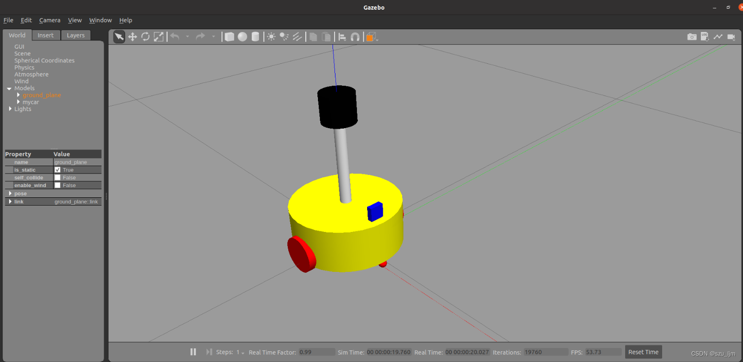
Finally, write the launch file and open the terminal to run the launch file. After configuring rviz and gazebo, you can see the robot model
<launch>
    <!-- 将 Urdf 文件的内容加载到参数服务器 -->
    <param name="robot_description" command="$(find xacro)/xacro $(find demo02_urdf_gazebo)/urdf/xacro/my_robot.urdf.xacro" />
    <!-- 启动 rviz -->
    <node pkg="rviz" type="rviz" name="rviz" />
    <node pkg="joint_state_publisher" type="joint_state_publisher" name="joint_state_publisher" output="screen" />
    <node pkg="robot_state_publisher" type="robot_state_publisher" name="robot_state_publisher" output="screen" />
    <node pkg="joint_state_publisher_gui" type="joint_state_publisher_gui" name="joint_state_publisher_gui" output="screen" />
    <!-- 启动 gazebo -->
    <include file="$(find gazebo_ros)/launch/empty_world.launch" />

    <!-- 在 gazebo 中显示机器人模型 -->
    <node pkg="gazebo_ros" type="spawn_model" name="model" args="-urdf -model mycar -param robot_description"  />
</launch>
Summarize
The above is the content of the ROS robot modeling and simulation study notes. By using ROS for robot modeling and simulation, the behavior and performance of the robot can be better understood and the design of the robot can be better optimized. In addition, ROS also provides a series of simulation tools, such as Gazebo and Stage, which can help engineers simulate robot behavior in different environments, so as to better understand the performance of robots under different conditions.
Robot modeling and simulation can also help engineers develop and test robot control algorithms, as well as evaluate robot performance and robustness. In addition, by using ROS for robot modeling and simulation, the interaction and communication between the various components of the robot system can be better understood, so that the software architecture of the robot system can be better designed and debugged.
In addition, robot modeling and simulation can also help engineers achieve rapid iteration and development, because testing and validation in a virtual environment is more efficient and flexible than testing and validating on an actual robot. By using ROS for robot modeling and simulation, problems in robotic systems can be identified and resolved more quickly, improving development efficiency and robot performance and reliability.