If there are errors in the code, terminology, etc. in the text, please correct me
Camera implementation principle BLOG: https://blog.csdn.net/qq_34060370/article/details/129391683
Article Directory
foreword
-
The two programs
In order to implement a simple orthographic camera that can watch objects in the scene
-
Camera related concepts
-
camera definition
It provides us with a way to observe the world. The camera observes all objects in the scene from a specific angle. Not only does it have a specific angle, but it can also adjust the field of view to observe the scene.
-
camera concept
The camera does not exist, but the projection and observation matrix coordinate space of the abstract camera is calculated , and the objects in the scene are first transformed into the observation matrix, and finally transformed into the projection matrix coordinate space.
-
camera properties
Fov field of view size, own position, aspect ratio, range of near and far planes, etc.
-
Camera observation matrix derivation
-
Introduce working methods
When the camera moves backwards, the objects in the scene actually move forward
The camera rotates to the right, in fact, the objects in the scene rotate to the left
-
How the camera observation matrix is calculated
The transformation matrix transform composed of the position of the camera and the rotation angle is inverse , and the matrix view is the observation matrix, and the object in the scene is transformed into this coordinate space by multiplying the observation matrix by this observation matrix .
Inversion is a method of calculating the observation matrix, and the second method is to use Euler angles + LookAt to calculate the observation matrix (this is the blog linked at the beginning of the article)
-
-
official
-
OpenGL
-
Write code sequence: project * view * world * verpos
After the camera moves, it is best to calculate the latest camera's proj*view matrix on the CPU and then pass it to GLSL
Because if the proj and view are transferred to the GPU, each object has to be multiplied by the proj*view matrix, which can be placed on the CPU so that it only needs to be done once + uploaded.
-
Reading order: from right to left
-
-
Directx
- Write code sequence: verpos * world * view * project
-
-
-
API design
Renderer::BeginScene(camera); Renderer::Submit(m_Shader1, VertexArray1);// 给场景提交要渲染的物体 Renderer::Submit(m_Shader2, VertexArray2);// 给场景提交要渲染的物体 Renderer::EndScene(); Renderer::Flush(); void BeingScene(Camera& camera){ // 在cpp中计算Project * view矩阵,并存储起来, this->ViewProjectionMatrix = camera.getProjectionMatrix() * camera.getViewMatrix(); } void Submit(Shader& shader, VertexArray& v){ shader->Bind(); // 着色器绑定 glUniformvec4("viewprojection", this->ViewProjectionMatrix);// 上传给Uniform v->bind(); // 绑定顶点数组 RenderCommand::DrawIndexed(vertexArray);// drawcall } -
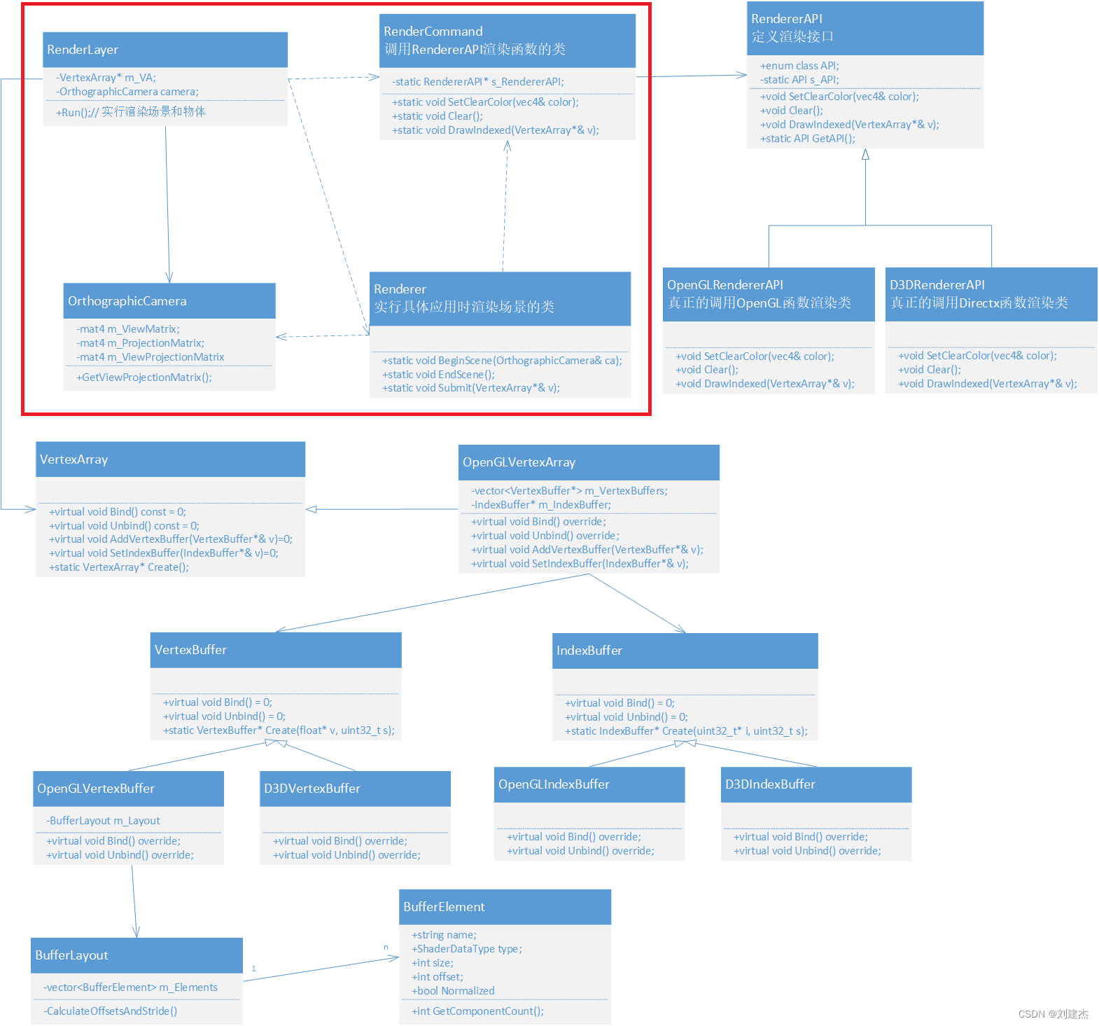
This section completes the class diagram
Record thinking points
key code
// 投影矩阵计算
OrthographicCamera::OrthographicCamera(float left, float right, float bottom, float top)
    : m_ProjectionMatrix(glm::ortho(left, right, bottom, top, -1.0f, 1.0f)), m_ViewMatrix(1.0f){


        m_ViewProjectionMatrix = m_ProjectionMatrix * m_ViewMatrix;
    }
// 投影观察矩阵
void OrthographicCamera::RecalculateViewMatrix(){


    glm::mat4 transform = glm::translate(glm::mat4(1.0f), m_Position) *
    glm::rotate(glm::mat4(1.0f), glm::radians(m_Rotation), glm::vec3(0, 0, 1)); // 绕z轴旋转

    m_ViewMatrix = glm::inverse(transform);
    // 投影观察矩阵
    m_ViewProjectionMatrix = m_ProjectionMatrix * m_ViewMatrix;
}
// 物体上传场景
void Renderer::Submit(const std::shared_ptr<Shader>& shader, const std::shared_ptr<VertexArray>& vertexArray){


    shader->Bind();// 着色器邦迪
    shader->UploadUniformMat4("u_ViewProjection", m_SceneData->ViewProjectionMatrix);// 上传到Uniform

    vertexArray->Bind();// 顶点数组绑定
    RenderCommand::DrawIndexed(vertexArray);// drawcall
}
void Shader::UploadUniformMat4(const std::string& name, const glm::mat4& matrix){


    GLint location = glGetUniformLocation(m_RendererID, name.c_str());// 获取uniform名称的位置
    glUniformMatrix4fv(location, 1, GL_FALSE, glm::value_ptr(matrix));// 根据位置上传
}
// glsl
uniform mat4 u_ViewProjection;// 声明uniform
void main(){


    v_Position = a_Position;
    v_Color = a_Color;
    gl_Position = vec4(a_Position, 1.0);
    // 将顶点变换到投影矩阵坐标空间(裁剪空间)下:projection * view * world * vpos
    gl_Position = u_ViewProjection * vec4(a_Position, 1.0);
}
About Window Scale Affecting Graphics Display
OrthographicCamera::OrthographicCamera(float left, float right, float bottom, float top)
    : m_ProjectionMatrix(glm::ortho(left, right, bottom, top, -1.0f, 1.0f)), m_ViewMatrix(1.0f){


    m_ViewProjectionMatrix = m_ProjectionMatrix * m_ViewMatrix;
}
Pre-points
-
The contrast between the top, bottom, left and right of the window is 1 and becomes 2

If the visible window is from 1 to 2, the range surrounded by the triangle 0.5 will shrink , so the graph will become smaller.
glm::ortho(-2, 2, -2, 2, -1.0f, 1.0f) gives a matrix value of
0.5 0 0 0 0 0.5 0 0 0 0 -1 0 0 0 0 1 -
Minified result

Specific issues
-
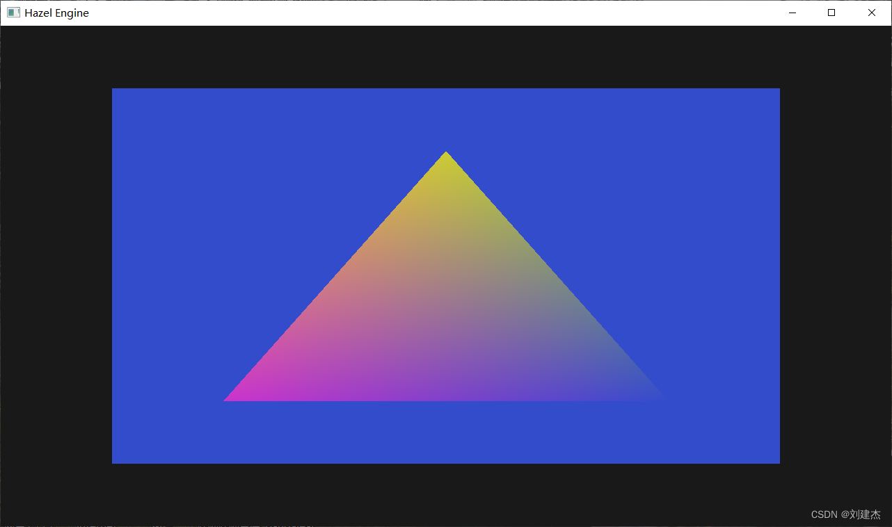
square to rectangle
The window is 1280 * 720. When glm::ortho(-1.0f,1.0f, -1.0f, 1.0f, -1.0f, 1.0f);, the original square blue quad becomes a rectangle
-
fix back to square
Under 1280*720, the left right needs to be passed in about 1280/720=1.7, and the width is enlarged, so that the left and right viewing angles become larger , and the wide range surrounded by objects shrinks , so that it becomes a square.
/*
由于窗口的大小是1280 :720,是16 / 9 = 1.77777
那么设置m_Camera的宽设置 1.6范围,高设为0.9就可以解决。或者 1.7与1也行
*/
Application::Application()
    :m_Camera(-1.6f, 1.6f, -0.9f, 0.9f){

      }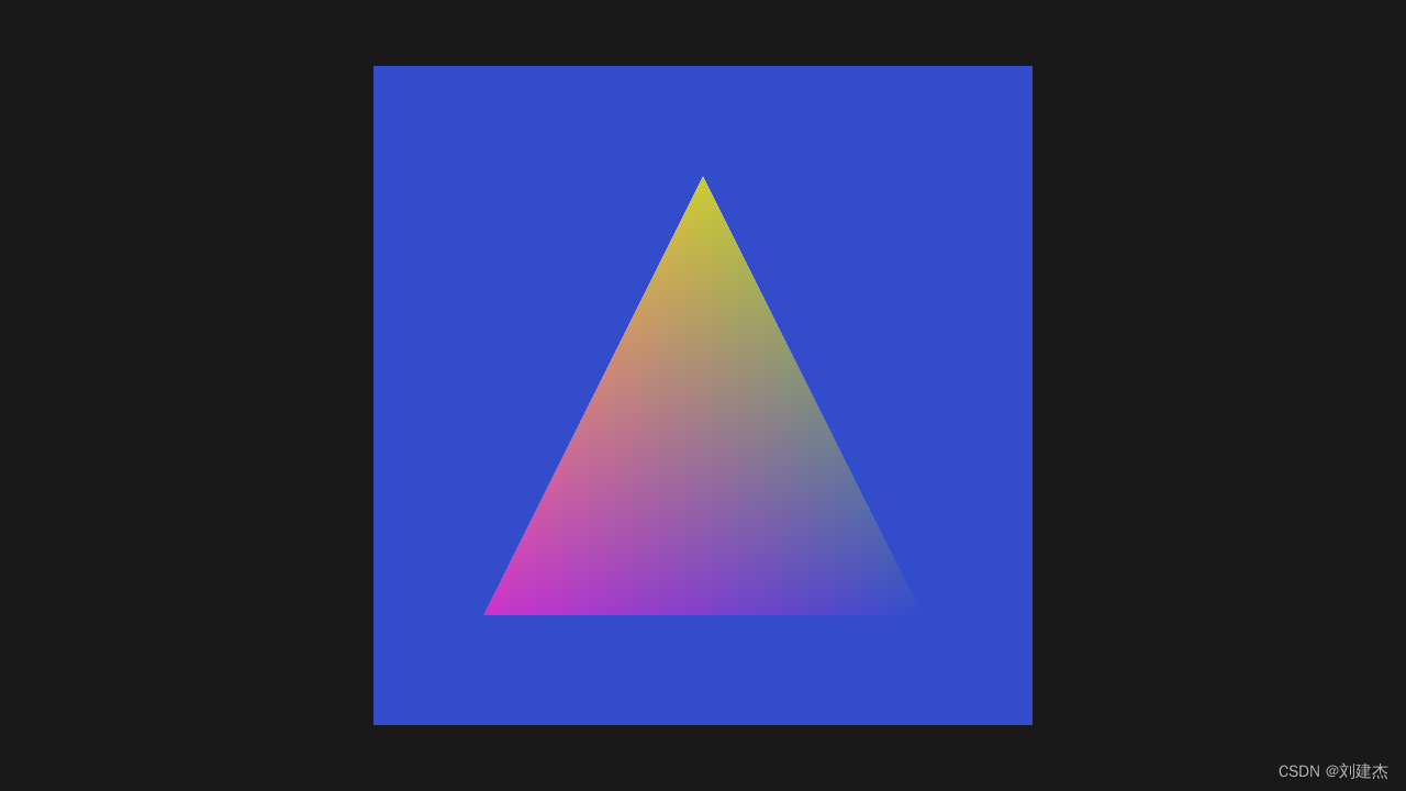
GLM library function related
-
glm:: ortho
left = -1.0f;right = 1.0f;bottom = -1.0f;top = 1.0f
glm::ortho(left,right, bottom, top, -1.0f, 1.0f);The resulting matrix is
1 0 0 0 0 1 0 0 0 0 -1 0 0 0 0 1 -
glm::translate(glm::mat4(1.0f), m_Position);
m_Position= {0.5f, 0.5f, 0.5f};
glm::mat4(1.0f), is a 4x4 identity matrix
1 0 0 0
0 1 0 0
0 0 1 0
0 0 0 1
glm::translate(glm::mat4(1.0f), m_Position);
/*
    glm::translate函数中
    mat<4, 4, T, Q> Result(m);
    Result[3] = m[0] * v[0] + m[1] * v[1] + m[2] * v[2] + m[3];
    Result[3]是第4行,m[0]是第1行,m[1]是第2行,m[2]是第3行。。。
    第四行  = (1 * 0.5,0,0,0) + (0, 1 * 0.5, 0, 0) + (0, 0, 1 * 0.5, 0) + (0, 0, 0, 1)
*/
// 最后的结果是// 有可能反了:第四行应该与第四列交换
1 	0 	0 	0
0 	1 	0 	0
0 	0 	1 	0
0.5 0.5 0.5 1
all codes
-
OrthographicCamera
class OrthographicCamera{


public:
    OrthographicCamera(float left, float right, float bottom, float top);
    const glm::vec3& GetPosition() const {

       return m_Position; }
    void SetPosition(const glm::vec3& position) {

       m_Position = position; RecalculateViewMatrix(); }
    float GetRotation() const {

       return m_Rotation; }
    void SetRotation(float rotation) {

       m_Rotation = rotation; RecalculateViewMatrix(); }
    const glm::mat4& GetProjectionMatrix() const {

       return m_ProjectionMatrix; }
    const glm::mat4& GetViewMatrix() const {

       return m_ViewMatrix; }
    const glm::mat4& GetViewProjectionMatrix() const {

       return m_ViewProjectionMatrix; }
private:
    void RecalculateViewMatrix();
 private:
    glm::mat4 m_ProjectionMatrix;
    glm::mat4 m_ViewMatrix;
    glm::mat4 m_ViewProjectionMatrix;
    glm::vec3 m_Position = {

       0.0f, 0.0f, 0.0f };// 位置
    float m_Rotation = 0.0f;					// 绕z轴的旋转角度
};
// 初始化用glm计算正交投影矩阵 OrthographicCamera::OrthographicCamera(float left, float right, float bottom, float top) : m_ProjectionMatrix(glm::ortho(left, right, bottom, top, -1.0f, 1.0f)), m_ViewMatrix(1.0f) { m_ViewProjectionMatrix = m_ProjectionMatrix * m_ViewMatrix; } // 投影观察矩阵计算 void OrthographicCamera::RecalculateViewMatrix() { // 观察矩阵 glm::mat4 transform = glm::translate(glm::mat4(1.0f), m_Position) * glm::rotate(glm::mat4(1.0f), glm::radians(m_Rotation), glm::vec3(0, 0, 1)); m_ViewMatrix = glm::inverse(transform); m_ViewProjectionMatrix = m_ProjectionMatrix * m_ViewMatrix; } -
Renderer
class Renderer{ public: static void BeginScene(OrthographicCamera& camera); // 开始场景 static void EndScene(); // 结束场景 static void Submit(const std::shared_ptr<Shader>& shader, const std::shared_ptr<VertexArray>& vertexArray);// 提交物体的顶点数组 inline static RendererAPI::API GetAPI() { return RendererAPI::GetAPI(); } private: struct SceneData { glm::mat4 ViewProjectionMatrix; }; static SceneData* m_SceneData; };Renderer::SceneData* Renderer::m_SceneData = new Renderer::SceneData; void Renderer::BeginScene(OrthographicCamera& camera){ m_SceneData->ViewProjectionMatrix = camera.GetViewProjectionMatrix(); // 保存计算的Projection * view矩阵 } void Renderer::EndScene(){ } void Renderer::Submit(const std::shared_ptr<Shader>& shader, const std::shared_ptr<VertexArray>& vertexArray){ shader->Bind(); // 着色器绑定 shader->UploadUniformMat4("u_ViewProjection", m_SceneData->ViewProjectionMatrix);// 上传投影观察矩阵 vertexArray->Bind();// 顶点数组绑定 RenderCommand::DrawIndexed(vertexArray);// drawcall } -
Shader
void UploadUniformMat4(const std::string& name, const glm::mat4& matrix); void Shader::UploadUniformMat4(const std::string& name, const glm::mat4& matrix){ GLint location = glGetUniformLocation(m_RendererID, name.c_str()); glUniformMatrix4fv(location, 1, GL_FALSE, glm::value_ptr(matrix)); } -
Application
OrthographicCamera m_Camera; private: static Application* s_Instance;Application::Application() : m_Camera(-1.6f, 1.6f, -0.9f, 0.9f){ // 着色器代码 std::string vertexSrc = R"( #version 330 core layout(location = 0) in vec3 a_Position; layout(location = 1) in vec4 a_Color; uniform mat4 u_ViewProjection; out vec3 v_Position; out vec4 v_Color; void main() { v_Position = a_Position; v_Color = a_Color; gl_Position = u_ViewProjection * vec4(a_Position, 1.0); } )"; void Application::Run(){ while (m_Running){ RenderCommand::SetClearColor({ 0.1f, 0.1f, 0.1f, 1 }); RenderCommand::Clear(); /* 5和6指明近和远平面范围 glm::ortho(left, right, bottom, top, -1.0f, 1.0f) 摄像机位置的z轴位置只要-1~1之间就行 */ m_Camera.SetPosition({ 0.5f, 0.5f, 0.0f }); m_Camera.SetRotation(45.0f); Renderer::BeginScene(m_Camera); // 绘制四边形 Renderer::Submit(m_BlueShader, m_SquareVA); // 绘制三角形 Renderer::Submit(m_Shader, m_VertexArray); Renderer::EndScene();