This article mainly introduces the embedded real-time operating system (RTOS), and takes uc/OS as an example, transplants it to stm32F103C8T6, and constructs 3 tasks: two of the tasks turn on and off the LED lights in 1s and 3s cycles respectively control; another task sends "hello uC/OS! Welcome to the RTOS multitasking environment!" through the serial port in a 2s cycle.
Table of contents
1. Task requirements
Learn embedded real-time operating system (RTOS) , take uc/OS as an example, transplant it to stm32F103 , and build at least 3 tasks (task) : Two of the tasks light up the LED lights in 1s and 3s cycles respectively- Turn off the control; another task sends "hello uC/OS! Welcome to the RTOS multitasking environment!" through the serial port in a 2s period. Document the detailed migration process.
2. Embedded real-time operating system (RTOS) - Introduction to uC/OS
2.1. Definition of RTOS
Embedded Real-time Operation System , abbreviated as (RTOS).
When external events or data are generated, they can be accepted and processed at a fast enough speed, and the processing results can control the production process or respond quickly to the processing system within the specified time, and control running embedded operating system.
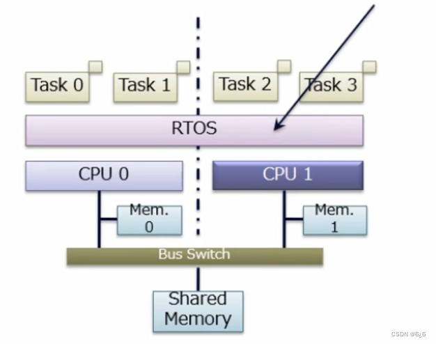
RTOS (Real Time OS) is a real-time operating system. According to the requirements of each task, it performs resource (including memory, peripherals, etc.) management, message management, task scheduling, and exception handling. In the system supported by RTOS, each task has a priority , and the RTOS dynamically switches each task according to the priority of each task to ensure the real-time requirements.
The real-time multitasking operating system runs multiple tasks in a time-sharing manner, and the switching between tasks is based on priority. Only the RTOS with priority service mode is the real real-time operating system.
In the fields of industrial control, military equipment, aerospace and other fields, there are strict requirements on the response time of the system, which requires the use of real-time systems. The embedded operating systems we often say are embedded real-time operating systems. Such as μC/OS-II , eCOS and Linux , HOPEN OS .
2.2 Introduction to uC/OS-III
uC/OS is an RTOS-like real-time operating system produced by Micrium . UCOS currently has two versions: UCOS-II and UCOS-III .
uC/OS-III (Micro C OS Three micro operating system written in C language version 3) is an upgradeable , hardenable, priority-based real-time kernel . Especially suitable for microprocessors and controllers, suitable for real-time operating systems (RTOS) of many commercial operating systems, it has no limit to number of tasks .
uC/OS-III is a third-generation system kernel that supports most of the functions expected from a modern real-time kernel. Such as resource management, synchronization, communication between tasks, and so on. However, uC/OS-III provides features that cannot be found in other real-time kernels, such as complete runtime measurement performance, sending signals or messages directly to tasks, tasks can wait for multiple kernel objects at the same time , etc. .
uC/OS-III is a scalable , curable, preemptive real-time kernel , and the number of tasks it manages is not limited. It is a third-generation kernel that provides all the features expected from a modern real-time kernel including resource management, synchronization, inter-task communication, and more. uC/OS-III also provides many features that are not available in other real-time kernels. For example, it can measure running performance at runtime, directly send signals or messages to tasks, and tasks can wait for multiple semaphores and message queues at the same time.
2.3. Components
μC/OS can be roughly divided into five parts: core , task processing, time processing, task synchronization and communication, and CPU transplantation.
-
Core part (OSCore.c) : It is the processing core of the operating system, including the initialization of the operating system, the operation of the operating system, the leading of the interrupt in and out, the clock tick, task scheduling, event processing and other parts; the parts that can maintain the here
-
Task processing part (OSTask.c) : The content in the task processing part is closely related to the operation of the task; including task creation, deletion, suspension, recovery, etc.
-
Clock part (OSTime.c) : The minimum clock unit in μC/OS-III is timetick (clock tick); operations such as task delay are completed here
-
Task synchronization and communication part : it is an event processing part, including semaphores, mailboxes, message queues, event flags, etc.; it is mainly used for interconnection between tasks and access to critical resources
-
CPU transplantation part : This part is usually written in assembly language because it involves system pointers such as SP; it mainly includes the underlying implementation of interrupt-level task switching, the underlying implementation of task-level task switching, the generation and processing of clock ticks, and the interrupt Relevant processing parts, etc.
2.4. Related concepts
- Tasks (threads) are simple programs. In a single CPU, only one task can be executed at any time .
Tasks look like C functions. In most embedded systems, tasks are usually in an infinite loop . A task cannot return a value like a C function.
In uC/OS-III , tasks are program entities , and uC/OS-III can manage and schedule these small tasks (programs). The task in uC/OS-III is made up of three parts: Task stack, task control block and task function .
- Task stack : The working environment used to save the task during context switching is the internal register value of STM32.
The task stack is an important part of the task. The stack is a continuous storage space organized in RAM according to the principle of "first in, first out (FIFO)". In order to meet the needs of saving the contents of CPU registers and calling other functions when tasks are switched and responding to interrupts, each task should have its own stack.
#define START_STK_SIZE 512 //Stack size
CPU_STK START_TASK_STK[START_STK_SIZE]; //Define an array as task stack
task stack initialization
If the task wants to switch back to the previous task and continue to run from the place where it was interrupted last time, just restore the scene, which is the internal registers of the CPU. Therefore, when creating a new task, the initial values of the CPU registers required by the system to start the task must be stored in the task stack in advance. In this way, when the task obtains the right to use the CPU, the content of the task stack is copied to each register of the CPU, so that the task can be started and run smoothly.
The work of storing the task initial data in the task stack is called task stack initialization, and uC/OS-III provides a function to complete stack initialization: OSTaskStkInit() .
Of course, users generally do not directly operate the stack initialization function, and the task stack initialization function is called by the task creation function OSTaskCreate() . Different CPUs operate differently on registers and stacks, so when transplanting uC/OS-III, users need to write task stack initialization functions according to their selected CPUs.
- Task control block : The task control block is used to record various attributes of the task.
The task control block is a data structure used to record information related to tasks , and each task must have its own task control block. When we use the OSTaskCreate() function to create a task, we assign a task control block to the task. Mission control blocks are created by the user.
OS_TCB StartTaskTCB; //Create a task control block
**USOCIII provides a function for task control block initialization: OS_TaskInitTCB(). **However, the user does not need to initialize the mission control block by itself. Because the same as the task stack initialization function, the function OSTaskCreate() will initialize the task control block of the task when creating the task.
- Task function : The task processing code written by the user. The task function is usually an infinite loop , or it can be a task that is executed only once. The parameter of the task is a void type, which can pass different types of data or even functions.
The task function is actually a C language function, but in the case of uC/OS-III, this function cannot be called by the user. When the task function is executed and when it is stopped is completely controlled by the operating system.
uC/OS-III supports time slice round-robin scheduling , so there will be multiple tasks under one priority, then we need to manage these tasks, here we use the OSRdyList[] array to manage these tasks.
Each element in the OSRdyList[] array corresponds to a priority. For example, OSRdyList[0] is used to manage all tasks under priority 0. OSRdyList[0] is of OS_RDY_LIST type. From the above OS_RDY_LIST structure, you can see the member variables: HeadPtr and TailPtr respectively point to OS_TCB . We know that OS_TCB can be used to construct a linked list , so all tasks under the same priority are through the linked list To manage , HeadPtr and TailPtr respectively point to the head and tail of this linked list, NbrEntries are used to record the number of tasks under this priority.
If there are multiple tasks at the same priority, the task pointed to by HeadPtr will always run first
2.5. Features
- Necessity ---- Embedded system software and hardware are becoming more and more complex.
- Miniaturization and reduction - the software and hardware are small and precise, just enough.
- Real-time ---- preemptive management strategy to meet the correctness of time.
- Reliability ---- Unattended, automatic equipment use requirements.
- Easy portability - easy to apply to a variety of hardware platforms.
- Microkernel ---- The code to complete the main functions of the OS is very small (additional functions need to be linked separately).
2.6. Basic functions
- Multi-task management -> Rich multi-task management functions allow target system designers to easily complete multi-task application design.
- Memory Management -> Dynamic memory management makes full use of hardware resources.
- Peripheral management -> such as I2C, UART, Timer, SPI and other device drivers.
2.7. Platform requirements for normal operation
- The processor's C compiler can generate reentrant code
- Interrupts can be turned on and off in C language
- The processor supports interrupts and can generate timed interrupts (typically between 10 and 100Hz)
- The processor supports a hardware stack capable of holding a certain amount of data (perhaps several kilobytes)
- The processor has instructions to read and store the stack pointer and other CPU registers to the stack or memory
2.8, data type
typedef unsigned char BOOLEAN;
typedef unsigned char INT8U;/无符号8位/
typedef signed char INT8S;/带符号8位/
typedef unsigned int INT16U;/无符号16位/
typedef signed int INT16S;/带符号16位/
typedef unsigned long INT32U;/无符号32位数/
typedef signed long INT32S;/带符号32位数/
typedef float FP32;/* 单精度浮点数*/
typedef double FP64;/* 双精度浮点数*/
typedef unsigned int OS_STK;/堆栈入口宽度/
typedef unsigned int OS_CPU_SR;/寄存器宽度/
2.9. Some functions used in porting
OSStartHighRdy() : This function is responsible for obtaining the stack pointer sp of the task from the TCB control block of the highest priority task after the OSStart() multitasking is started, and restores the CPU site in turn through sp, and the system will hand over the control right to The process of the task created by the user until the task is blocked or the CPU is preempted by other higher-priority tasks; this function is only executed once when multi-tasking is started, and is used to start the first one, which is the highest priority
OSCtxSw() for task-level execution : This function is a task-level context switching function. It is executed when the task actively requests and CPU scheduling because it is blocked. Obtain the stack pointer of the highest priority task, restore the CPU site of this task from the stack, and make it continue to execute, thus completing a task switching OSIntExit(
) : This function is an interrupt-level task switching function, found in the clock interrupt ISR When a high-priority task is waiting, it is necessary not to return to the interrupted task after the interrupt exits, but to directly schedule the ready high-priority task for execution; the purpose is to allow the high-priority task to be responded as soon as possible to ensure the system's Real-time performance
OSTickISR() : This function is a clock interrupt processing function. Its main task is to handle clock interrupts and call the OSTimeTick function implemented by the system . If there is a high-priority task waiting for the clock signal, it needs to be scheduled for execution at the interrupt level; The other two related functions are OSIntEnter() and OSIntExit() , both of which need to be executed in the ISR
Let's take a look at how to implement the multitasking operation under the RTOS system
3. Project creation
3.1. Create a project using STM32CubeMX
-
Open STM32CubeMX , double-click ACCESS TO MCU SELECTOR

-
Enter STM32F103C8 in the search box , double-click STM32F103C8Tx or select it and click Start Project in the upper right corner to enter the configuration interface

-
Click Pinout & Configuration , select RCC , and set HSE to Crystal/Ceramic Resonator

-
Click SYS , set Debug to Serial Wire

-
Configure the serial port USART1 , click Connectivity , click USART1 , and set Mode to Asynchronous

-
Set PA5 and PC13 as the output ports of the two LEDs , and set PA5 and PC13 as GPIO-Output

-
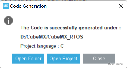
Generate the project after setting the project name, storage path and compilation environment


-
Click Open Project to open the project
3.2. Get ucOS
Link: https://pan.baidu.com/s/1P2NXc64Q_2c1tXRAvWY3xQ?pwd=2022
Extraction code: 2022
3.3. Preparations
-
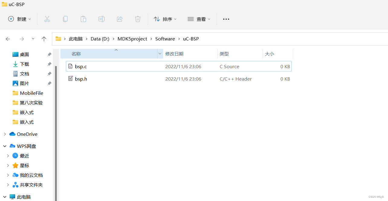
Create new bsp.c and bsp.h files in the uC-BSP folder
-
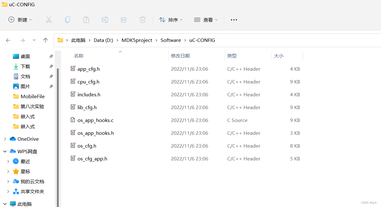
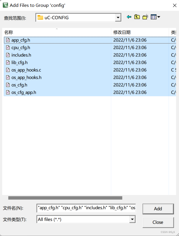
Copy app_cfg.h, cpu_cfg.h, includes.h, lib_cfg.h, os_app_hooks.c, os_app_hook.h, os_cfg.h, os_cfg_app.h to the folder uC-CONFIG
-
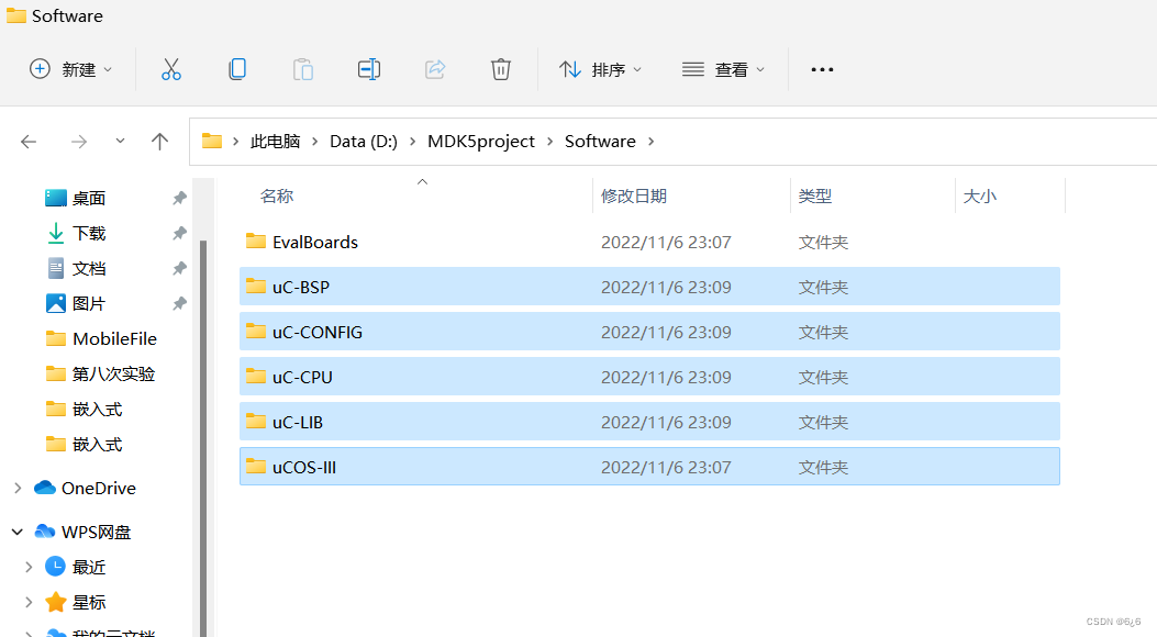
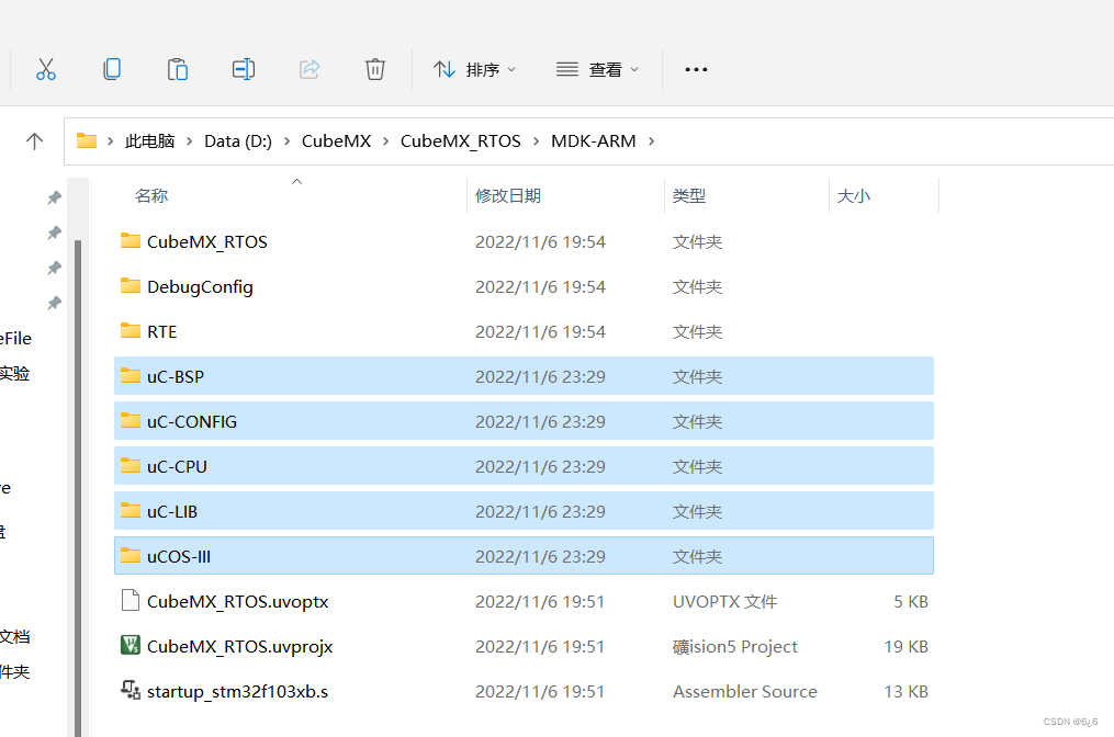
Copy the uC-BSP, uC-CONFIG, uC-CPU, uC-LIB, uCOS-III files of Software to the MDK -ARM folder of the CubeMX_RTOS project
3.4, uCOS transplantation
-
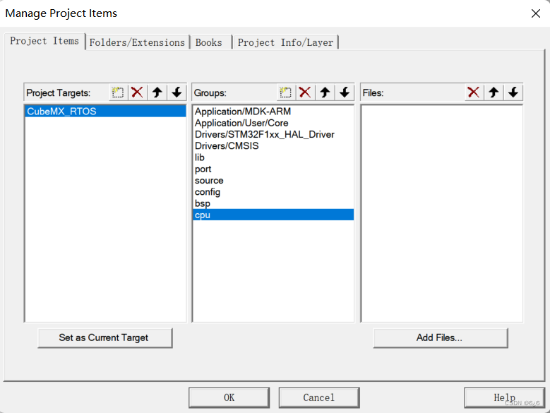
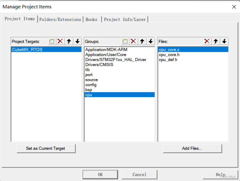
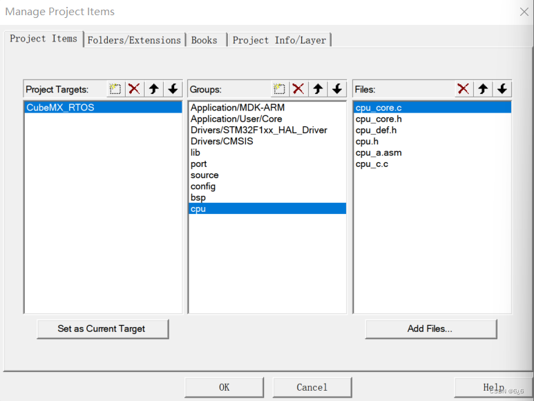
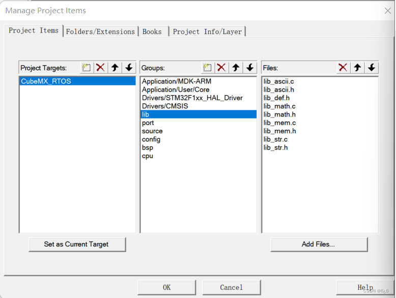
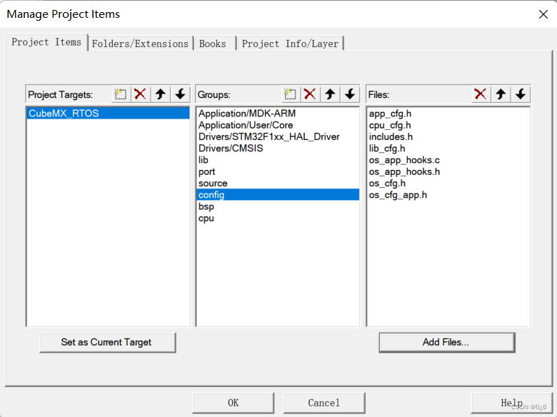
Open the project file generated using CubeMX , right-click the CubeMX_RTOS (project) file, click Manage Project Items or directly click Manage Project Items on the toolbar

-
Add the following folders under Groups
-
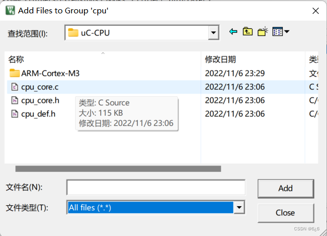
Click cpu–>Add Files... , under the MDK-ARM\uC-CPU path, select All files for the file type , select the following files, and click Add to add
-
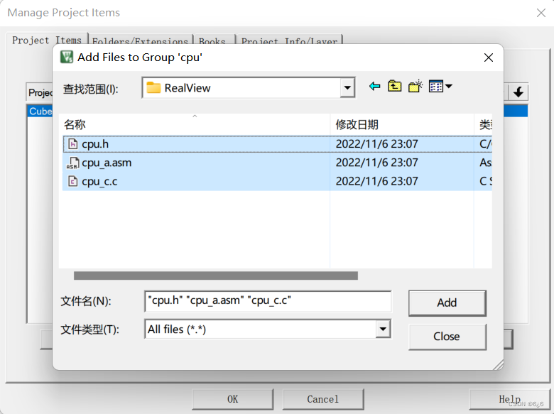
Then select the following files in the MDK-ARM\uC-CPU\ARM-Cortex-M3\RealView path, and click Add to add
-
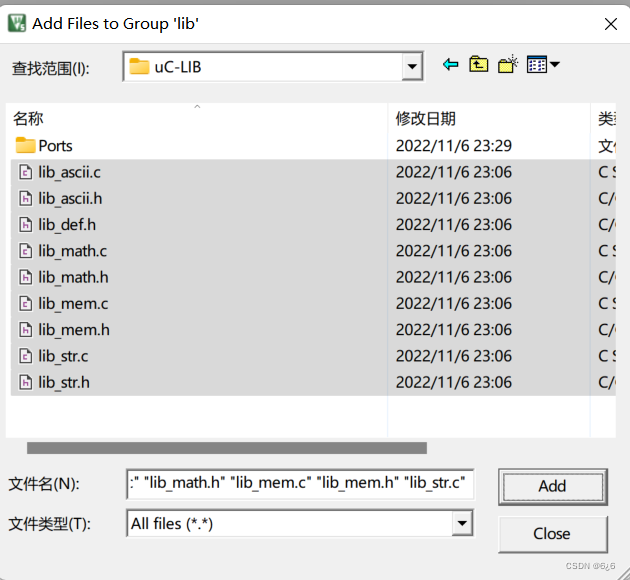
Click lib–>Add Files... , select the file below in the MDK-ARM\uC-LIB path, and click Add to add
-
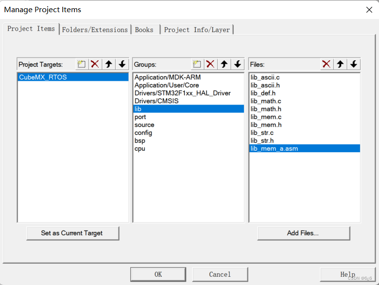
Then under the MDK-ARM\uC-LIB\Ports\ARM-Cortex-M3\RealView path, select the following files and click Add to add

-
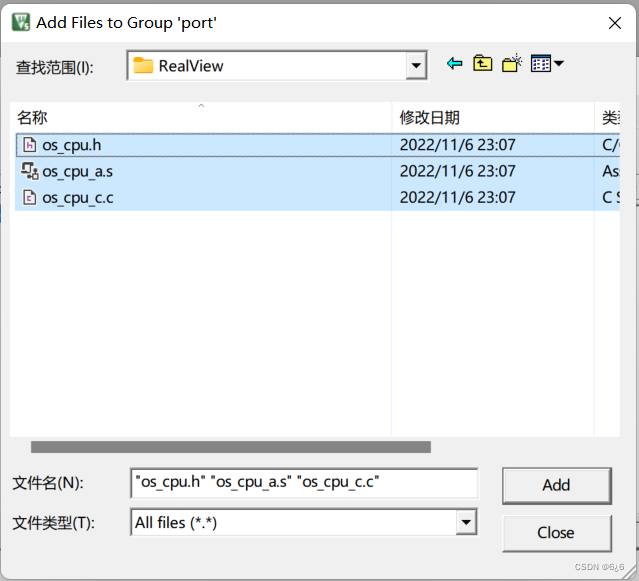
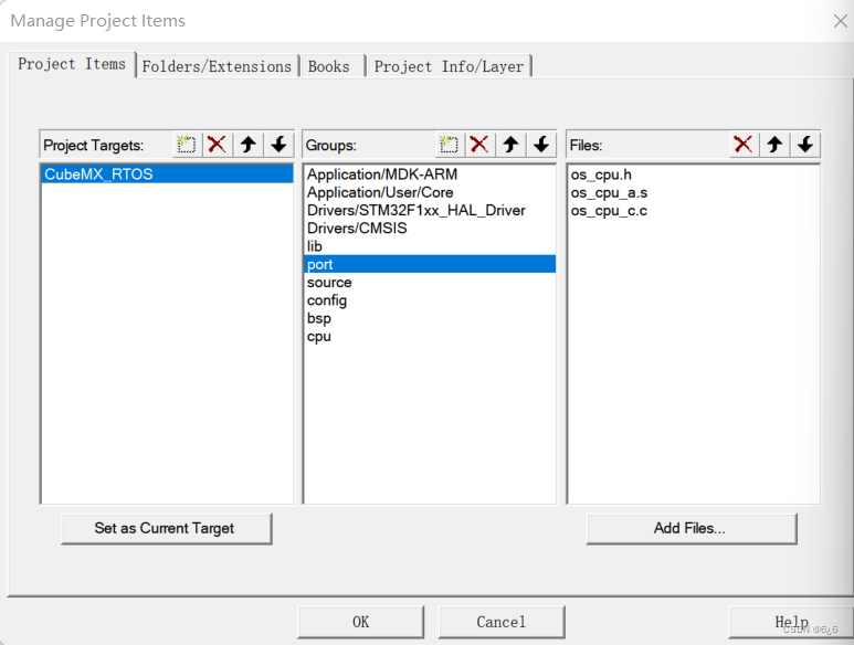
Click port–>Add Files… , in the MDK-ARM\uCOS-III\Ports\ARM-Cortex-M3\Generic\RealView path, select the following files, and click Add to add
-
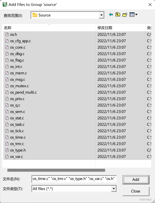
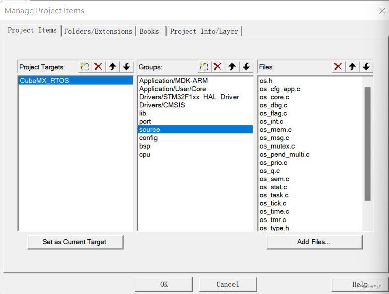
Click source–>Add Files… , select all the following .c .h files in the MDK-ARM\uCOS-III\Source path, and click Add to add
-
Click config–>Add Files… , select all files in the MDK-ARM\uC-CONFIG path, and click Add to add
-
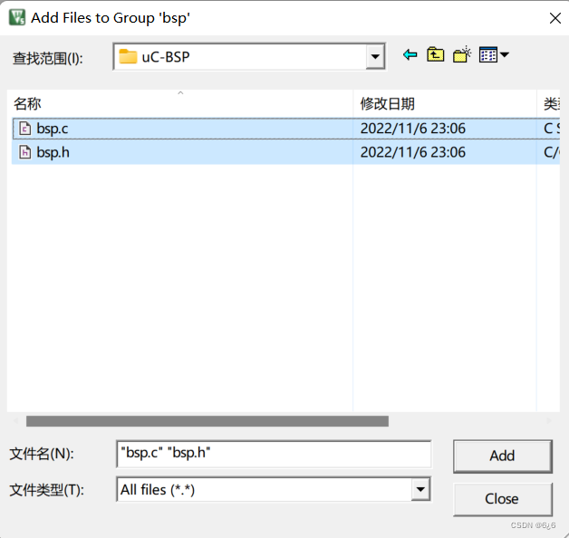
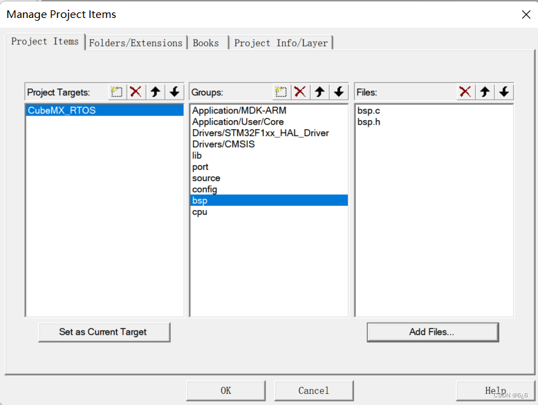
Click bsp–>Add Files… , select all files under the LMDK-ARM\uC-BSP path, and click Add to add
-
Import the file path, click Magic Wand -> C/C+±> (behind Include Paths)... -> Add , and then add the following path

4. Code writing
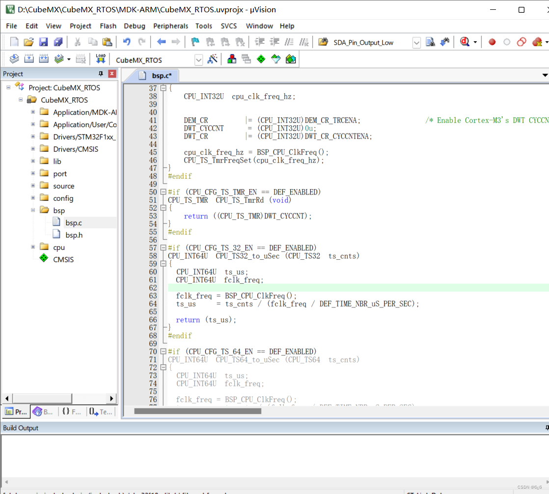
- Add the following code in bsp.c
#include "includes.h"

#define  DWT_CR      *(CPU_REG32 *)0xE0001000
#define  DWT_CYCCNT  *(CPU_REG32 *)0xE0001004
#define  DEM_CR      *(CPU_REG32 *)0xE000EDFC
#define  DBGMCU_CR   *(CPU_REG32 *)0xE0042004

#define  DEM_CR_TRCENA                   (1 << 24)
#define  DWT_CR_CYCCNTENA                (1 <<  0)

CPU_INT32U  BSP_CPU_ClkFreq (void)
{


    return HAL_RCC_GetHCLKFreq();
}

void BSP_Tick_Init(void)
{


	CPU_INT32U cpu_clk_freq;
	CPU_INT32U cnts;
	cpu_clk_freq = BSP_CPU_ClkFreq();

	#if(OS_VERSION>=3000u)
		cnts = cpu_clk_freq/(CPU_INT32U)OSCfg_TickRate_Hz;
	#else
		cnts = cpu_clk_freq/(CPU_INT32U)OS_TICKS_PER_SEC;
	#endif
	OS_CPU_SysTickInit(cnts);
}
void BSP_Init(void)
{


	BSP_Tick_Init();
	MX_GPIO_Init();
}

#if (CPU_CFG_TS_TMR_EN == DEF_ENABLED)
void  CPU_TS_TmrInit (void)
{


    CPU_INT32U  cpu_clk_freq_hz;


    DEM_CR         |= (CPU_INT32U)DEM_CR_TRCENA;                /* Enable Cortex-M3's DWT CYCCNT reg.                   */
    DWT_CYCCNT      = (CPU_INT32U)0u;
    DWT_CR         |= (CPU_INT32U)DWT_CR_CYCCNTENA;

    cpu_clk_freq_hz = BSP_CPU_ClkFreq();
    CPU_TS_TmrFreqSet(cpu_clk_freq_hz);
}
#endif

#if (CPU_CFG_TS_TMR_EN == DEF_ENABLED)
CPU_TS_TMR  CPU_TS_TmrRd (void)
{


    return ((CPU_TS_TMR)DWT_CYCCNT);
}
#endif

#if (CPU_CFG_TS_32_EN == DEF_ENABLED)
CPU_INT64U  CPU_TS32_to_uSec (CPU_TS32  ts_cnts)
{


  CPU_INT64U  ts_us;
  CPU_INT64U  fclk_freq;

  fclk_freq = BSP_CPU_ClkFreq();
  ts_us     = ts_cnts / (fclk_freq / DEF_TIME_NBR_uS_PER_SEC);

  return (ts_us);
}
#endif

#if (CPU_CFG_TS_64_EN == DEF_ENABLED)
CPU_INT64U  CPU_TS64_to_uSec (CPU_TS64  ts_cnts)
{


	CPU_INT64U  ts_us;
	CPU_INT64U  fclk_freq;

  fclk_freq = BSP_CPU_ClkFreq();
  ts_us     = ts_cnts / (fclk_freq / DEF_TIME_NBR_uS_PER_SEC);

  return (ts_us);
}
#endif
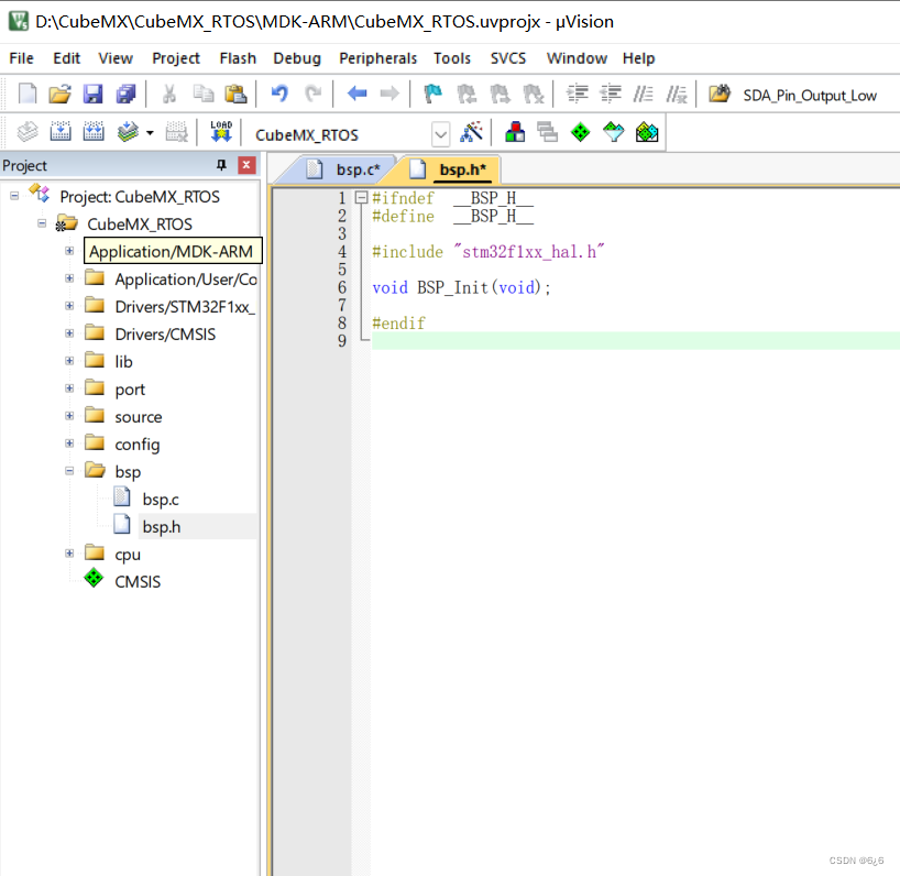
- Add the following code in bsp.h
#ifndef  __BSP_H__
#define  __BSP_H__

#include "stm32f1xx_hal.h"

void BSP_Init(void);

#endif
-
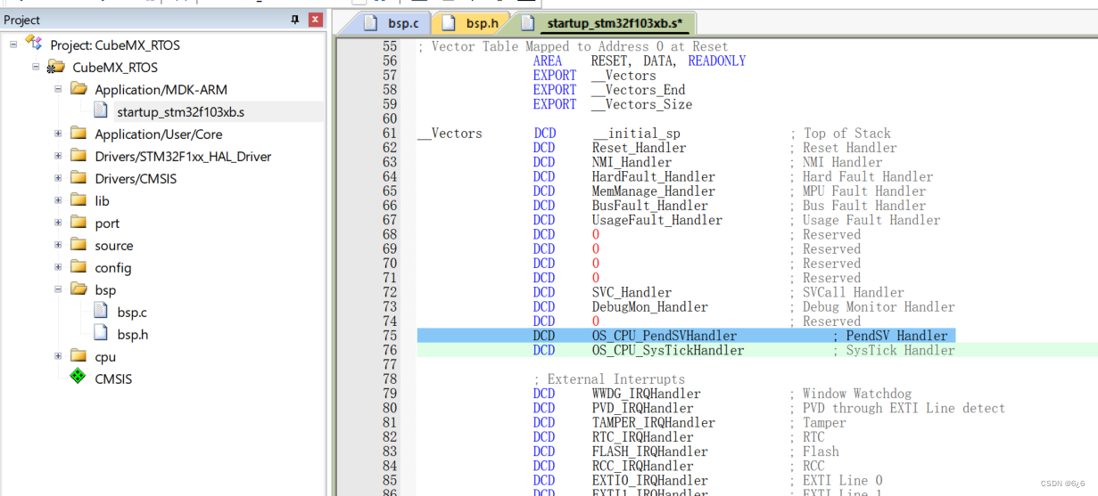
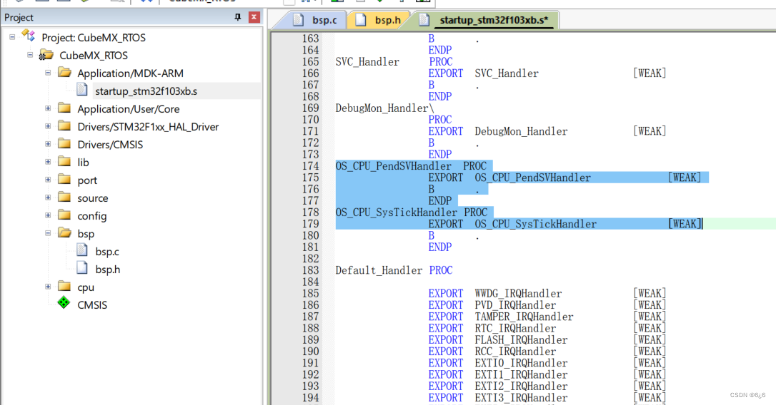
In the following two locations (lines 75, 76 and 174-179) of the startup_stm32f103xb.s (under Application/MDK-ARM) file , change
toPendSV_HandlerOS_CPU_PendSVHandlerSysTick_HandlerOS_CPU_SysTickHandler
-
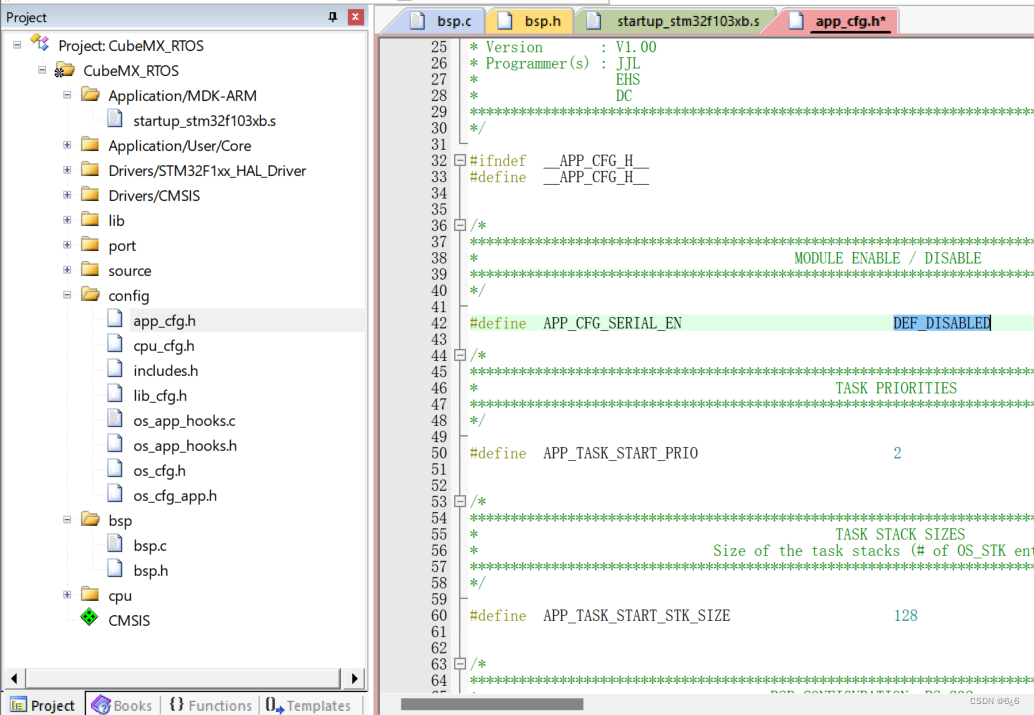
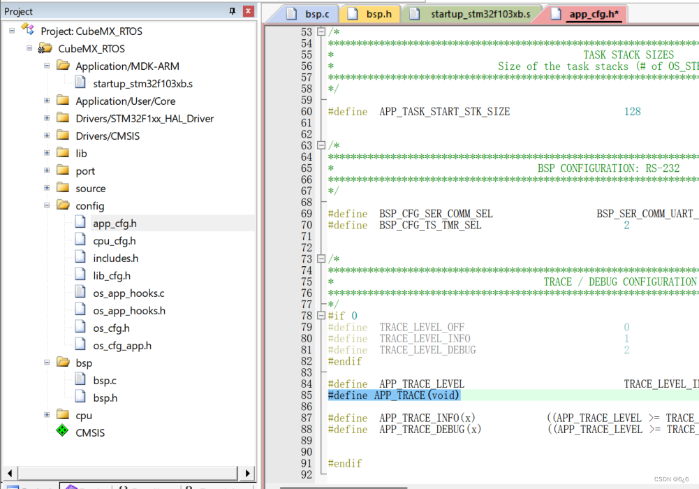
Modify the code of the app_cfg.h (under config) file:
DEF_ENABLEDchangeDEF_DISABLED
#define APP_TRACE BSP_Ser_Printfto#define APP_TRACE(void)
-
Modify the code of the includes.h file, add
#include <bsp.h>below and#include "gpio.h"change to#include "app_cfg.h"#include <stm32f10x_lib.h>#include "stm32f1xx_hal.h"

-
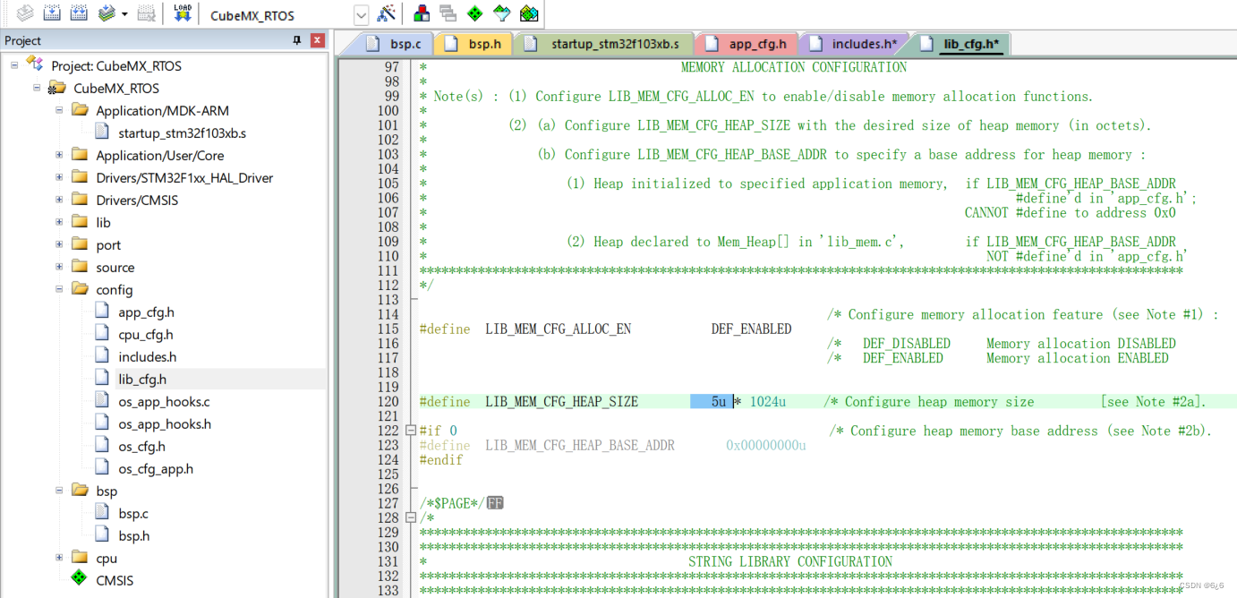
Modify the lib_cfg.h file code, modify 27u to 5u
-
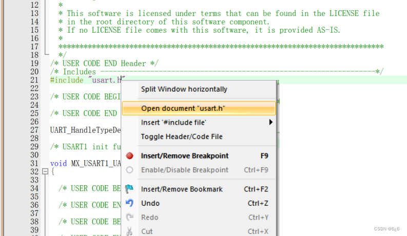
Modify the usart.c file code, add code to complete printf redirection
int fputc(int ch,FILE *f){


	HAL_UART_Transmit(&huart1,(uint8_t *)&ch,1,0xffff);
	return ch;
}

- Swipe up
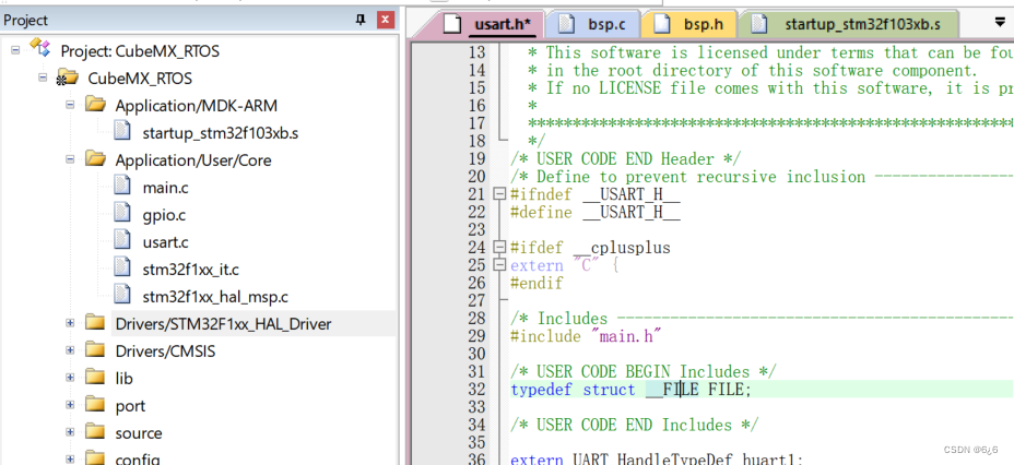
#include "usart.h", right click on the .h file, click, modify the usart.h file code, and add a definition code:
typedef struct __FILE FILE;
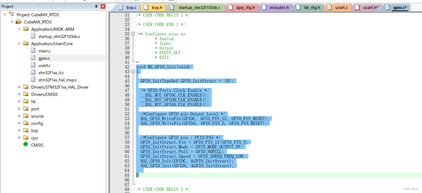
- Initialize the pins and modify the code in the gpio.c file:
void MX_GPIO_Init(void)
{


  GPIO_InitTypeDef GPIO_InitStruct = {

    0};

  /* GPIO Ports Clock Enable */
  __HAL_RCC_GPIOC_CLK_ENABLE();
  __HAL_RCC_GPIOD_CLK_ENABLE();
  __HAL_RCC_GPIOA_CLK_ENABLE();

  /*Configure GPIO pin Output Level */
  HAL_GPIO_WritePin(GPIOC, GPIO_PIN_13, GPIO_PIN_RESET);
	HAL_GPIO_WritePin(GPIOA, GPIO_PIN_5, GPIO_PIN_RESET);


  /*Configure GPIO pin : PC13|PA5 */
  GPIO_InitStruct.Pin = GPIO_PIN_13|GPIO_PIN_5;
  GPIO_InitStruct.Mode = GPIO_MODE_OUTPUT_PP;
  GPIO_InitStruct.Pull = GPIO_NOPULL;
  GPIO_InitStruct.Speed = GPIO_SPEED_FREQ_LOW;
  HAL_GPIO_Init(GPIOC, &GPIO_InitStruct);
	HAL_GPIO_Init(GPIOA, &GPIO_InitStruct);

}
- Write the code for main.c
/* Includes ------------------------------------------------------------------*/
#include "main.h"
#include "gpio.h"
#include "usart.h"
/* Private includes ----------------------------------------------------------*/
/* USER CODE BEGIN Includes */
#include <includes.h>
#include "stm32f1xx_hal.h"
/* USER CODE END Includes */
/* Private typedef -----------------------------------------------------------*/
/* USER CODE BEGIN PTD */
/* USER CODE END PTD */
/* Private define ------------------------------------------------------------*/
/* USER CODE BEGIN PD */
/* 任务优先级 */
#define START_TASK_PRIO 3
#define LED0_TASK_PRIO 4
#define MSG_TASK_PRIO 5
#define LED1_TASK_PRIO 6
/* 任务堆栈大小 */
#define START_STK_SIZE 96
#define LED0_STK_SIZE 64
#define MSG_STK_SIZE 64
#define LED1_STK_SIZE 64
/* 任务栈 */
CPU_STK START_TASK_STK[START_STK_SIZE];
CPU_STK LED0_TASK_STK[LED0_STK_SIZE];
CPU_STK MSG_TASK_STK[MSG_STK_SIZE];
CPU_STK LED1_TASK_STK[LED1_STK_SIZE];
/* 任务控制块 */
OS_TCB StartTaskTCB;
OS_TCB Led0TaskTCB;
OS_TCB MsgTaskTCB;
OS_TCB Led1TaskTCB;
/* USER CODE END PD */
/* Private macro -------------------------------------------------------------*/
/* USER CODE BEGIN PM */
/* USER CODE END PM */
/* Private variables ---------------------------------------------------------*/
/* USER CODE BEGIN PV */
/* 任务函数定义 */
void start_task(void *p_arg);
static void AppTaskCreate(void);
static void AppObjCreate(void);
static void led_pc13(void *p_arg);
static void send_msg(void *p_arg);
static void led_pa5(void *p_arg);
/* USER CODE END PV */
/* Private function prototypes -----------------------------------------------*/
void SystemClock_Config(void);
/* USER CODE BEGIN PFP */
/* USER CODE END PFP */
/* Private user code ---------------------------------------------------------*/
/* USER CODE BEGIN 0 */
/**
* @brief System Clock Configuration
* @retval None
*/
void SystemClock_Config(void)
{
RCC_OscInitTypeDef RCC_OscInitStruct = {
0};
RCC_ClkInitTypeDef RCC_ClkInitStruct = {
0};
/**Initializes the CPU, AHB and APB busses clocks
*/
RCC_OscInitStruct.OscillatorType = RCC_OSCILLATORTYPE_HSE;
RCC_OscInitStruct.HSEState = RCC_HSE_ON;
RCC_OscInitStruct.HSEPredivValue = RCC_HSE_PREDIV_DIV1;
RCC_OscInitStruct.HSIState = RCC_HSI_ON;
RCC_OscInitStruct.PLL.PLLState = RCC_PLL_ON;
RCC_OscInitStruct.PLL.PLLSource = RCC_PLLSOURCE_HSE;
RCC_OscInitStruct.PLL.PLLMUL = RCC_PLL_MUL9;
if (HAL_RCC_OscConfig(&RCC_OscInitStruct) != HAL_OK)
{
Error_Handler();
}
/**Initializes the CPU, AHB and APB busses clocks
*/
RCC_ClkInitStruct.ClockType = RCC_CLOCKTYPE_HCLK|RCC_CLOCKTYPE_SYSCLK
|RCC_CLOCKTYPE_PCLK1|RCC_CLOCKTYPE_PCLK2;
RCC_ClkInitStruct.SYSCLKSource = RCC_SYSCLKSOURCE_PLLCLK;
RCC_ClkInitStruct.AHBCLKDivider = RCC_SYSCLK_DIV1;
RCC_ClkInitStruct.APB1CLKDivider = RCC_HCLK_DIV2;
RCC_ClkInitStruct.APB2CLKDivider = RCC_HCLK_DIV1;
if (HAL_RCC_ClockConfig(&RCC_ClkInitStruct, FLASH_LATENCY_2) != HAL_OK)
{
Error_Handler();
}
}
/* USER CODE END 0 */
/**
* @brief The application entry point.
* @retval int
*/
int main(void)
{
OS_ERR err;
OSInit(&err);
HAL_Init();
SystemClock_Config();
//MX_GPIO_Init(); 这个在BSP的初始化里也会初始化
MX_USART1_UART_Init();
/* 创建任务 */
OSTaskCreate((OS_TCB *)&StartTaskTCB, /* Create the start task */
(CPU_CHAR *)"start task",
(OS_TASK_PTR ) start_task,
(void *) 0,
(OS_PRIO ) START_TASK_PRIO,
(CPU_STK *)&START_TASK_STK[0],
(CPU_STK_SIZE) START_STK_SIZE/10,
(CPU_STK_SIZE) START_STK_SIZE,
(OS_MSG_QTY ) 0,
(OS_TICK ) 0,
(void *) 0,
(OS_OPT )(OS_OPT_TASK_STK_CHK | OS_OPT_TASK_STK_CLR),
(OS_ERR *)&err);
/* 启动多任务系统,控制权交给uC/OS-III */
OSStart(&err); /* Start multitasking (i.e. give control to uC/OS-III). */
}
void start_task(void *p_arg)
{
OS_ERR err;
CPU_SR_ALLOC();
p_arg = p_arg;
/* YangJie add 2021.05.20*/
BSP_Init(); /* Initialize BSP functions */
//CPU_Init();
//Mem_Init(); /* Initialize Memory Management Module */
#if OS_CFG_STAT_TASK_EN > 0u
OSStatTaskCPUUsageInit(&err); //统计任务
#endif
#ifdef CPU_CFG_INT_DIS_MEAS_EN //如果使能了测量中断关闭时间
CPU_IntDisMeasMaxCurReset();
#endif
#if OS_CFG_SCHED_ROUND_ROBIN_EN //当使用时间片轮转的时候
//使能时间片轮转调度功能,时间片长度为1个系统时钟节拍,既1*5=5ms
OSSchedRoundRobinCfg(DEF_ENABLED,1,&err);
#endif
OS_CRITICAL_ENTER(); //进入临界区
/* 创建LED0任务 */
OSTaskCreate((OS_TCB * )&Led0TaskTCB,
(CPU_CHAR * )"led_pc13",
(OS_TASK_PTR )led_pc13,
(void * )0,
(OS_PRIO )LED0_TASK_PRIO,
(CPU_STK * )&LED0_TASK_STK[0],
(CPU_STK_SIZE)LED0_STK_SIZE/10,
(CPU_STK_SIZE)LED0_STK_SIZE,
(OS_MSG_QTY )0,
(OS_TICK )0,
(void * )0,
(OS_OPT )OS_OPT_TASK_STK_CHK|OS_OPT_TASK_STK_CLR,
(OS_ERR * )&err);
/* 创建LED1任务 */
OSTaskCreate((OS_TCB * )&Led1TaskTCB,
(CPU_CHAR * )"led_pa5",
(OS_TASK_PTR )led_pa5,
(void * )0,
(OS_PRIO )LED1_TASK_PRIO,
(CPU_STK * )&LED1_TASK_STK[0],
(CPU_STK_SIZE)LED1_STK_SIZE/10,
(CPU_STK_SIZE)LED1_STK_SIZE,
(OS_MSG_QTY )0,
(OS_TICK )0,
(void * )0,
(OS_OPT )OS_OPT_TASK_STK_CHK|OS_OPT_TASK_STK_CLR,
(OS_ERR * )&err);
/* 创建MSG任务 */
OSTaskCreate((OS_TCB * )&MsgTaskTCB,
(CPU_CHAR * )"send_msg",
(OS_TASK_PTR )send_msg,
(void * )0,
(OS_PRIO )MSG_TASK_PRIO,
(CPU_STK * )&MSG_TASK_STK[0],
(CPU_STK_SIZE)MSG_STK_SIZE/10,
(CPU_STK_SIZE)MSG_STK_SIZE,
(OS_MSG_QTY )0,
(OS_TICK )0,
(void * )0,
(OS_OPT )OS_OPT_TASK_STK_CHK|OS_OPT_TASK_STK_CLR,
(OS_ERR * )&err);
OS_TaskSuspend((OS_TCB*)&StartTaskTCB,&err); //挂起开始任务
OS_CRITICAL_EXIT(); //进入临界区
}
/**
* 函数功能: 启动任务函数体。
* 输入参数: p_arg 是在创建该任务时传递的形参
* 返 回 值: 无
* 说 明:无
*/
static void led_pc13 (void *p_arg)
{
OS_ERR err;
(void)p_arg;
BSP_Init(); /* Initialize BSP functions */
CPU_Init();
Mem_Init(); /* Initialize Memory Management Module */
#if OS_CFG_STAT_TASK_EN > 0u
OSStatTaskCPUUsageInit(&err); /* Compute CPU capacity with no task running */
#endif
CPU_IntDisMeasMaxCurReset();
AppTaskCreate(); /* Create Application Tasks */
AppObjCreate(); /* Create Application Objects */
while (DEF_TRUE)
{
HAL_GPIO_WritePin(GPIOC,GPIO_PIN_13,GPIO_PIN_RESET);
OSTimeDlyHMSM(0, 0, 1, 0,OS_OPT_TIME_HMSM_STRICT,&err);
HAL_GPIO_WritePin(GPIOC,GPIO_PIN_13,GPIO_PIN_SET);
OSTimeDlyHMSM(0, 0, 1, 0,OS_OPT_TIME_HMSM_STRICT,&err);
/* USER CODE END WHILE */
/* USER CODE BEGIN 3 */
}
/* USER CODE END 3 */
}
static void led_pa5 (void *p_arg)
{
OS_ERR err;
(void)p_arg;
BSP_Init(); /* Initialize BSP functions */
CPU_Init();
Mem_Init(); /* Initialize Memory Management Module */
#if OS_CFG_STAT_TASK_EN > 0u
OSStatTaskCPUUsageInit(&err); /* Compute CPU capacity with no task running */
#endif
CPU_IntDisMeasMaxCurReset();
AppTaskCreate(); /* Create Application Tasks */
AppObjCreate(); /* Create Application Objects */
while (DEF_TRUE)
{
HAL_GPIO_WritePin(GPIOA,GPIO_PIN_5,GPIO_PIN_RESET);
OSTimeDlyHMSM(0, 0, 3, 0,OS_OPT_TIME_HMSM_STRICT,&err);
HAL_GPIO_WritePin(GPIOA,GPIO_PIN_5,GPIO_PIN_SET);
OSTimeDlyHMSM(0, 0, 3, 0,OS_OPT_TIME_HMSM_STRICT,&err);
/* USER CODE END WHILE */
/* USER CODE BEGIN 3 */
}
/* USER CODE END 3 */
}
static void send_msg (void *p_arg)
{
OS_ERR err;
(void)p_arg;
BSP_Init(); /* Initialize BSP functions */
CPU_Init();
Mem_Init(); /* Initialize Memory Management Module */
#if OS_CFG_STAT_TASK_EN > 0u
OSStatTaskCPUUsageInit(&err); /* Compute CPU capacity with no task running */
#endif
CPU_IntDisMeasMaxCurReset();
AppTaskCreate(); /* Create Application Tasks */
AppObjCreate(); /* Create Application Objects */
while (DEF_TRUE)
{
printf("hello uc/OS!欢迎来到RTOS多任务环境! \r\n");
OSTimeDlyHMSM(0, 0, 2, 0,OS_OPT_TIME_HMSM_STRICT,&err);
/* USER CODE END WHILE */
/* USER CODE BEGIN 3 */
}
/* USER CODE END 3 */
}
/* USER CODE BEGIN 4 */
/**
* 函数功能: 创建应用任务
* 输入参数: p_arg 是在创建该任务时传递的形参
* 返 回 值: 无
* 说 明:无
*/
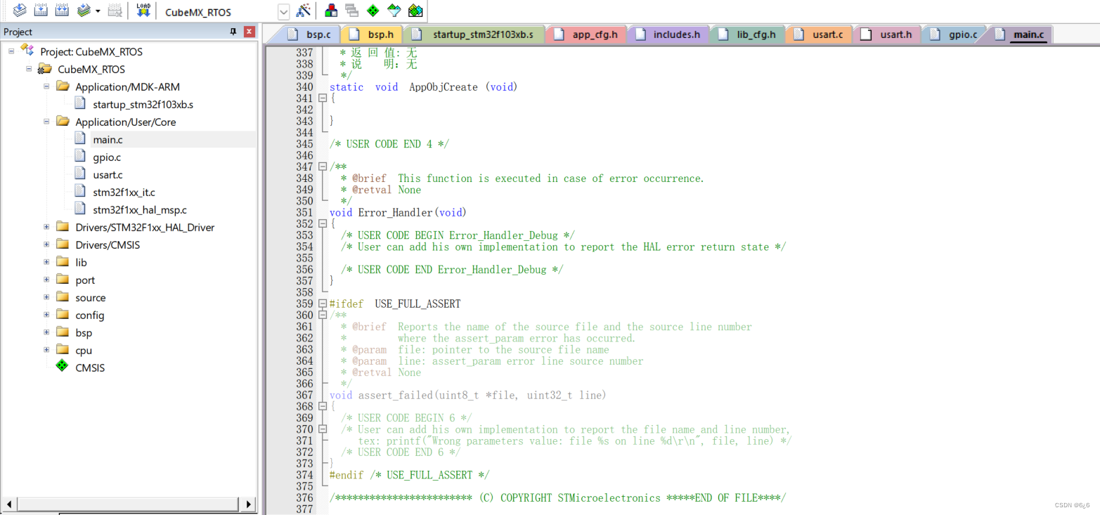
static void AppTaskCreate (void)
{
}
/**
* 函数功能: uCOSIII内核对象创建
* 输入参数: 无
* 返 回 值: 无
* 说 明:无
*/
static void AppObjCreate (void)
{
}
/* USER CODE END 4 */
/**
* @brief This function is executed in case of error occurrence.
* @retval None
*/
void Error_Handler(void)
{
/* USER CODE BEGIN Error_Handler_Debug */
/* User can add his own implementation to report the HAL error return state */
/* USER CODE END Error_Handler_Debug */
}
#ifdef USE_FULL_ASSERT
/**
* @brief Reports the name of the source file and the source line number
* where the assert_param error has occurred.
* @param file: pointer to the source file name
* @param line: assert_param error line source number
* @retval None
*/
void assert_failed(uint8_t *file, uint32_t line)
{
/* USER CODE BEGIN 6 */
/* User can add his own implementation to report the file name and line number,
tex: printf("Wrong parameters value: file %s on line %d\r\n", file, line) */
/* USER CODE END 6 */
}
#endif /* USE_FULL_ASSERT */
/************************ (C) COPYRIGHT STMicroelectronics *****END OF FILE****/
OSTimeDlyHMSM (CPU_INT16U hours, CPU_INT16U minutes, CPU_INT16U seconds, CPU_INT32U milli, OS_OPT opt, OS_ERR *p_err) function is used to delay, control the LED on and off cycle and serial communication cycle, the specific parameters are as follows: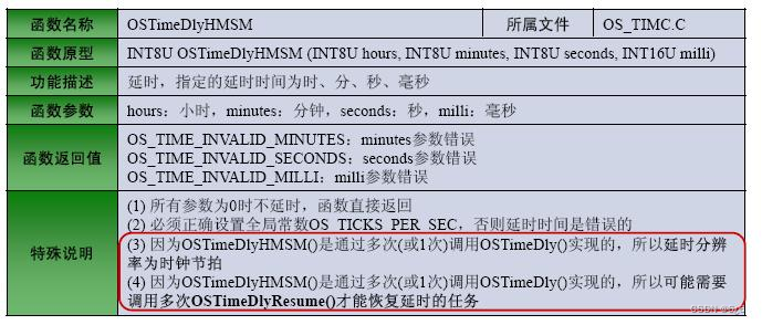
5. Compile and burn
5.1. Set up the compilation environment
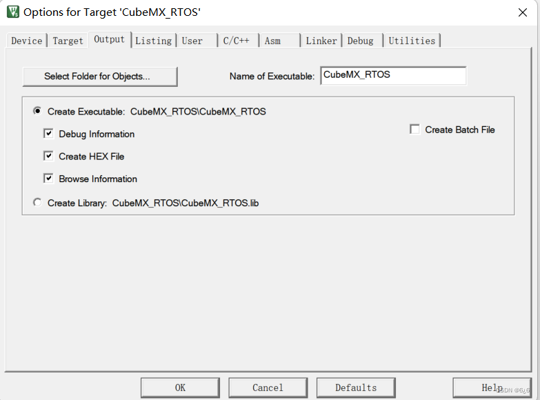
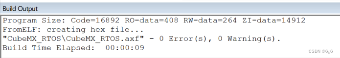
Click the magic wand, check Use MicroLIB in Code Generation under Target , and change the Size of IRAM1 to 0x8000

- Check Create HEX File under Output
5.2, compile
- Click compile to generate a HEX file
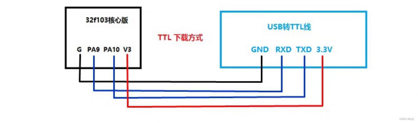
5.3. Hardware connection
| USB to TTL | STM32F103C8T6 |
|---|---|
| GND | G |
| 3V3 | 3V3 |
| RXD | PA9 |
| TXD | PA10 |
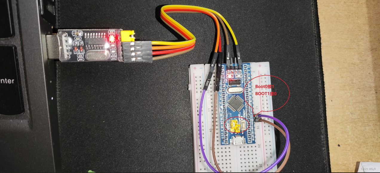
Note that BOOT0 on the core board is set to 1, and BOOT1 is set to 0
LED module connection method:
| output port | destination port |
|---|---|
| 3.3V | LED long legs |
| PA5 | LED short legs |
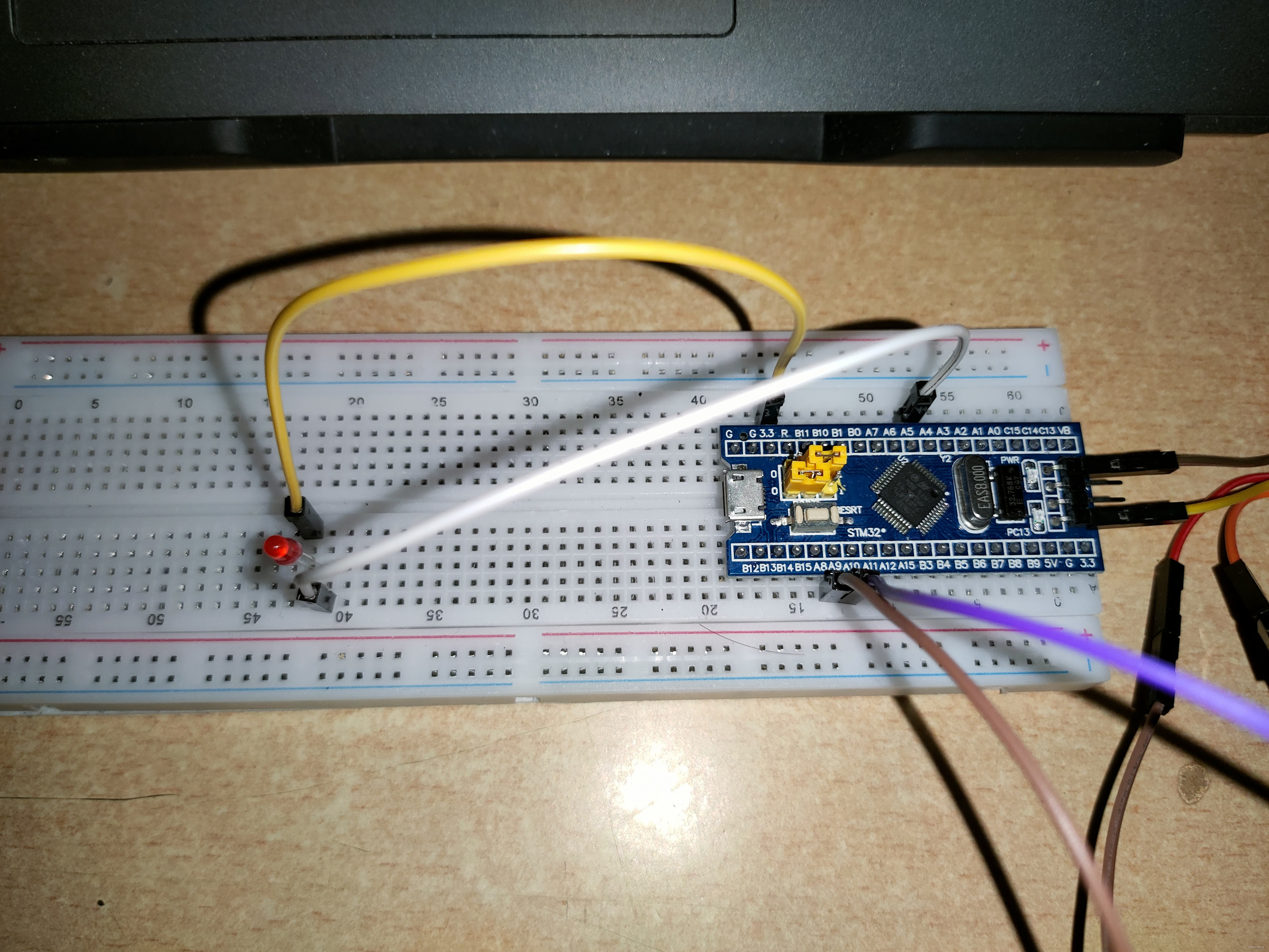
PC13 is connected to the LED on the board, so as to drive the LED on the board to realize the operation of turning on and off the light
5.4, burning
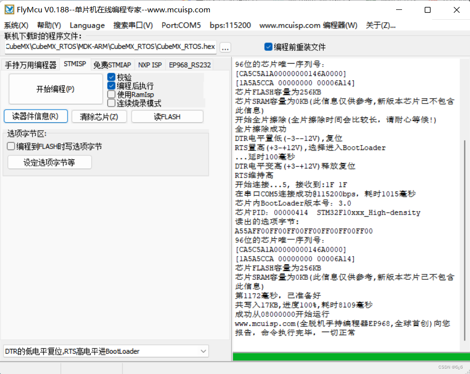
Connect the USB to TTL to the USB port of the computer, open the FlyMcu burning assistant to burn
5.5. Achievement effect
-
The LED (red) connected to PA5 turns on and off in a period of three seconds, and the LED (green) on the board connected to PC13 turns on and off in a period of one second
The red light changes once every three seconds, and the green light changes once every second
-
STM32F103C8T6 sends a sentence "hello uc/OS! Welcome to the RTOS multitasking environment!" through the serial port to the computer every two seconds!
STM32 sends information to the computer every two seconds through the serial port
6. Summary
This experiment mainly introduces the embedded real-time operating system ( RTOS ), and on the basis of theoretical knowledge, taking uc/OS as an example, it is transplanted to stm32F103C8T6 , and three tasks are realized at the same time: two of them are 1s and 1s respectively The cycle of 3s is used to control the LED lights on and off; the other is to send "hello uc/OS! Welcome to the RTOS multitasking environment!" through the serial port with a cycle of 2s .
This experiment not only deepened my understanding of real-time operating systems, but also deepened my understanding of multitasking knowledge. Many problems were encountered during the completion of this experiment, and the implementation process was cumbersome and took a lot of time. And in the process of implementation, many files need to be added. When adding, it is necessary not to add repeatedly, nor to add less, otherwise it will cause compilation errors or fail to run.
In this experiment, the OSTimeDlyHMSM function is used to control the time, which is much simpler than the previous timing, but the generated HEX file is obviously much larger than the previous file, and the compilation and burning time is longer than before.
Through this practical operation, I have improved my ability to discover, analyze and solve problems. Finally, thank you for reading, and welcome to point out the problems in this article!
Reference list:
1. STM32F103C8T6 porting uCOS based on HAL library
2. STM32F103C8T6 porting uC/OS-III based on HAL library super complete detailed process
3. STM32F103C8 porting uCOSIII (HAL library)
4. STM32F103C8T6 porting uC/OS-III and logic based on HAL library Analyzer waveform observation