Case overview
I just finished an IDC project recently and happened to have two H3Cs as storage switches to provide 10Gb iSCSI mounts. I didn’t have much contact with H3C stacking before. This time it’s just a record, including the pits that are easy to hit in the middle of the configuration.
Introduction to IRF
Different from the traditional physical stack, IRF is a logical stack, which is different from Cisco's vPC logic. Its usage and corresponding scenarios are closer to the traditional stacking mode, which is easier to understand and use. The following quotes the official introduction
:
IRF (Intelligent Resilient Framework) is a software virtualization technology independently developed by H3C. Its core idea is to connect multiple devices together through IRF physical ports, and after necessary configuration, virtualize them into a "distributed device". Using this virtualization technology can integrate the hardware resources and software processing capabilities of multiple devices to achieve collaborative work, unified management and uninterrupted maintenance of multiple devices. For ease of description, this "virtual device" is also called IRF. Therefore, IRF in this article has two meanings, one refers to IRF technology, and the other refers to IRF equipment.
IRF mainly has the following advantages:
• Simplified management: After IRF is formed, users can log in to the IRF system through any port of any member device to manage all member devices in the IRF in a unified manner.
• High reliability: The high reliability of the IRF is reflected in many aspects. For example, the IRF is composed of multiple member devices. The Master device is responsible for the operation, management and maintenance of the IRF. The Slave device can also process services while serving as a backup. Once the Master device fails, the system will quickly and automatically elect a new Master to ensure service interruption, thereby realizing the 1:N backup of the device; in addition, the IRF links between member devices support the aggregation function, and the IRF and the upper and lower device The physical links among them also support the aggregation function, and multiple links can back up each other or perform load sharing, thus further improving the reliability of the IRF.
• Powerful network expansion capability: By adding member devices, you can easily expand the number of ports and bandwidth of IRF. Because each member device has a CPU that can independently process protocol packets and forward packets, the IRF can easily expand its processing capacity.
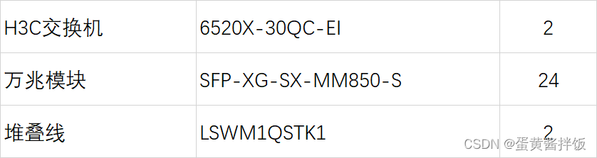
Equipment List
The following list is directly drawn from the contract, 2 sets of full 10 Gigabit optical 6520, 40Gb uplink, 2 40Gb cables with modules, directly used for IRF
Configuration Ideas and Precautions
Before configuration, you need to understand two concepts:
IRF member roles:
divided into Master and Slave, where the Master is responsible for managing the entire IRF, and the Slave operates as the backup device of the Master. When the Master fails, the system will automatically elect a new Master from the Slave to take over the work of the original Master. Both Master and Slave are elected by roles. Only one Master can exist in an IRF at the same time, and other member devices are all Slaves. Master and Slave are elected through the member priority of the device itself, the higher the priority, the greater the possibility of being elected as the Master
IRF interface: a logical interface
dedicated to IRF , which needs to be bound to a physical port to take effect
The configuration ideas are as follows:
1. Configure the IRF member numbers and priorities of the two switches.
2. Configure the IRF interfaces and corresponding physical ports of the two switches (note that the logical IRF ports of the two switches are the same as the traditional physical stack ports. Cross-tail interconnection is required, so if you configure 1/1 and 2/1, you cannot negotiate stacking normally, you need to configure 1/1 and 2/2 or 1/2 and 2/1)
3. Enable IRF and wire
configuration process
The following is the actual configuration process
Master switch configuration
#配置irf成员及优先级
[H3C]irf member 1 priority 30
[H3C]quit
<H3C>reboot
#临时关闭需要irf的相关物理接口
[H3C]interface range FortyGigE 1/0/25 to FortyGigE 1/0/26
[H3C-if-range]shutdown
[H3C-if-range]quit
#配置irf接口并将对应的物理接口加入
[H3C]irf-port 1/2
[H3C-irf-port1/2]port group interface FortyGigE 1/0/25
[H3C-irf-port1/2]port group interface FortyGigE 1/0/26
[H3C-irf-port1/2]quit
#启用物理接口
[H3C]interface range FortyGigE 1/0/25 to FortyGigE 1/0/26
[H3C-if-range]undo shutdown
[H3C-if-range]quit
[H3C]save
#启用irf配置
[H3C]irf-port-configuration active
Slave switch configuration
[H3C] irf member 1 priority 20
[H3C] irf member 1 renumber 2
Renumbering the member ID may result in configuration change or loss. Continue? [Y/N]:y
[H3C]interface range FortyGigE 2/0/25 to FortyGigE 2/0/26
[H3C-if-range]shutdown
[H3C-if-range]quit
[H3C]irf-port 2/1
[H3C-irf-port2/1]port group interface FortyGigE 2/0/25
[H3C-irf-port2/1]port group interface FortyGigE 2/0/26
[H3C-irf-port2/1]quit
[H3C]interface range FortyGigE 2/0/25 to FortyGigE 2/0/26
[H3C-if-range]undo shutdown
[H3C-if-range]quit
[H3C]save
[H3C]irf-port-configuration active
Finally, 25-25, 26-26 connect the two 40Gb, the switch will automatically complete the election and restart work, after all the interface configuration and related irf information can be seen in currentconfig:
#
 irf mac-address persistent timer
 irf auto-update enable
 undo irf link-delay
 irf member 1 priority 30
 irf member 2 priority 20
#
irf-port 1/2
 port group interface FortyGigE1/0/25
 port group interface FortyGigE1/0/26
#
irf-port 2/1
 port group interface FortyGigE2/0/25
 port group interface FortyGigE2/0/26
#
Finally, some other conventional configurations such as Hostname, vlan, stp and other configurations will not be discussed in this article.