There is too little knowledge about the powerlink protocol on the Internet, and it is too scattered and fragmented, which makes it easy for people to plunge into it and get confused. Novices may not know what the purpose is when they see the demo source code. In fact, the use of the Powerlink protocol is quite simple, especially for those who have experience in using the Canopen protocol. Here is an overview of the use of the powerlink protocol as a whole, and share it with more interested partners to participate in improving the ecology of Powerlink. The following content will be continuously improved and supplemented and updated irregularly.
The following describes what Powerlink is, what its advantages are, what it can be used for, and how to use it, etc., to see and grasp it from a global perspective. Let newcomers avoid detours and understand and use the powerlink protocol faster.
Introduction to Powerlink
POWERLINK was first developed and launched by B&R in 2001, and the initial intellectual property rights belonged to B&R. Similar to Siemens, B&R has a complete product system. Its original intention was to provide a complete set of hardware and software solutions just like Siemens. The single problem is that the customer base of the product is not as extensive as Siemens, and later the "bureau" therCat appeared, so POVERLTNK lost its monopoly and closed foundation. So B&R gave up the patent and intellectual property rights of POWERLINK in 2009, so POWERLINK has become an open source technology like Linux.
It is an efficient industrial Ethernet fieldbus protocol. Powerlink simply modifies the standard Ethernet data link layer and disables the CSMA/CD mechanism, so that the master station completely controls the data sending and receiving process on the network, thereby ensuring strict time characteristics and realizing real-time communication functions. The software implementation of Powerlink only modifies the network driver of the traditional operating system, removes the interrupt-based network IO process, and only retains the network card initialization and sending and receiving functions. The sending of the network data of the master station is triggered by a high-precision clock, and the IO operation is performed with the slave station at regular intervals. Generally, the master-slave station directly uses the form of the master station to poll the slave station to transmit real-time synchronous data, and transmits ordinary data that is not required by real-time in the latter part of a cycle.
The Powerlink protocol is very open, including an open source software and FPGA to implement openPowerlink, and there is an open source OpenConfigurator software to configure the entire network, which can save part of the code development work and can reconfigure the entire network when the network is running. network.
The Powerlink protocol uses the CanOpen protocol at the application layer, and user programming is basically an object dictionary, PDO (process data object) and SDO (service data object) and the definition of their mapping relationship. The object corresponds to the data unit on our device, such as an 8bit input data, 32bit long integer data, and string, time, temperature and so on. A set of data objects constitutes an object dictionary. PDO is a synchronous real-time data object, and SDO is asynchronous and non-real-time. CanOpen defines some industrial automation equipment specifications, which will describe in detail which data types, indexes, and sub-indexes a certain type of equipment should support. Generally speaking, developing a powerlink device should implement the definition of the specification in the same way as developing a CanOpen device.

Principle of Powerlink
In order to avoid conflicts and maximize the use of bandwidth in the transmission of Powerlink network packets, the data exchange between devices is based on time slots. A device in the powerlink network is called the management node (MN), which controls the communication function. It defines the synchronous clock pulses of all nodes and assigns the transmission rights to each slave device. The remaining nodes are called slave control nodes (CN).
The powerlink cycle is divided into four time periods (figure):
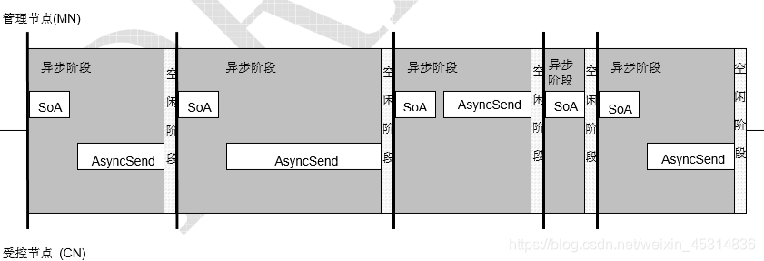
If no node (including MN) is assigned, the next POWERLINK short cycle starts without waiting for any timeout.
The allocation mechanism used for asynchronous phases in isochronous POWERLINK cycles shall also apply to short POWERLINK cycles.
The data link layer of POWERLINK is the core of POWERLINK, mainly including the following functions:
-
Construct/analyze data frames, control the delimitation of data frames, network synchronization, and the sequence of sending and receiving data frames.
-
Flow control, error detection, and data encapsulation of raw data at the physical layer during transmission.
-
Transport control for real-time communications.
-
Network state machine.
In the POWERLINK network, at least one device acts as the master station (MN), and other devices act as slave stations (CN).
Each slave device has a unique node number (NodeId), which is used to distinguish devices in the network, and the value range is 1-239. The node number of the master station equipment (MN) is 240. The function of the master station is to coordinate each slave station, reasonably allocate the right to use the bus, avoid conflicts, and realize real-time communication.
POWERLINK's real-time communication mechanism: POWERLINK has two communication mechanisms, based on request/response mode and based on timing active reporting mode (PRC mode).
Any topology can be implemented by using hubs. The number of hubs is no longer limited due to the fact that only one device sends at a time and no collisions occur. From a design point of view, this is a clear advantage, if the PowerLink device already has an integrated 2-port hub line structure can easily implement Ethernet for the application interface. powerlink V2 is based on the canopen communication protocol DS301 CAN defined mechanism in automation (EN50325-4). This opens up a wide range of ready-to-use device and application profiles for powerlink, canopen and enables continuity of communication services between powerlink systems, facilitating the migration from canopen to ethernet powerlink at the software level.
Advantages of Powerlink
1. Open source is free, whether it is open source c code or VHDL implementation code, it is available for study, research and commercial application.
2. The solution is flexible. For occasions where the real-time requirement is not very high at the millisecond level, a complete software solution is sufficient. For occasions that require subtle levels, there are FPGA solutions that can be substituted.
3. The performance is extremely high. If FPGA and Gigabit network card are used, the cycle time of 9us can be achieved.
4. Implemented CANopen (CANopen is an application layer protocol, which provides a unified interface for applications, so that there is a unified access method between different devices and applications).
5. It has a good reputation and technical support in China, and some units and organizations work together to build an ecology.
6. Conducive to innovation and patent mining. Based on the open source protocol stack, anyone can publish their own research results. At present, there are many papers and invention patents based on the PowerLink protocol.
7. There are many mature cases.
Maixin's 400us, 8-axis servo control system based on PowerLink protocol:

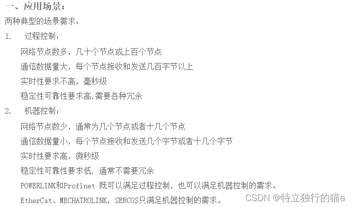
Although there are various bus technologies such as can bus and 485 bus, they also have advantages and disadvantages. The following are several typical application scenarios of powerlink:
openPOWERLINK Introduction
openPOWERLINK is the open source c code implementation of the POWERLINK protocol stack. It is a platform-independent highly modular real-time communication solution. In addition to the previously supported operating system platforms such as Linux, Windows, VxWorks and FPGA slave stations, the new version 2.0 supports Besides ALETRA and XILINX, the new scheme also includes the realization of TI's Sitara chip.
More introductions and source codes about openPOWERLINK can be obtained from Sourceforge:
openPOWERLINK :: openPOWERLINK
Development preparation
Overview of the development process
Development of the slave station
Development of the master station
The use of demos
Slave demo code
Main station demo code
test verification
Code flow analysis
Introduction to openCONFIGURATOR tool
Introduction to CANopen protocol standard
About CIA301 and CIA402 standards
The CANopen protocol is based on the CIA (CANopen Protocol International Association) standard, which includes many sub-protocols, and the two most commonly used sub-protocols are CIA 301 and CIA 402. CIA 301 is the basic protocol in the CANopen protocol, which mainly defines the physical layer, data link layer and object dictionary of the CANopen network. It defines the data format, frame format, data transmission, command and response of the CAN bus, and defines the structure and rules of the object dictionary. All CANopen devices must follow the CIA 301 standard. CIA 402 is a device preset protocol for motion control that defines specific functions for controlling motor drives and position control. On the basis of CIA 301, it adds some object dictionaries and operation codes related to motion control, and specifies some special requirements for motion control equipment. CIA 402 defines a variety of drive and actuator control methods, including speed control, position control, current control and other control modes, making the CANopen protocol applicable to a wide range of automation control fields. To sum up, CIA 301 is the basic protocol in the CANopen protocol, which specifies the basic rules that all CANopen devices must follow, while CIA 402 is an important sub-protocol in the CANopen protocol, which defines the The specific function of position control makes the CANopen protocol applicable to a wide range of automation control fields.
Comply with the CIA (CANopen International Association) protocol standard to ensure compatibility and interoperability with other devices in the network. These standards define the format, structure and communication protocols used by different devices in the network, ensuring that all devices can communicate with each other even if they are made by different manufacturers. If you want to customize the data and functions, in addition to the CANopen protocol provides a standardized object dictionary for defining the parameters, configuration and status information of the device. You can also add custom objects to the dictionary to define the functionality you want to achieve. However, before any modifications are made to the network, it must be ensured that these modifications do not violate CIA standards and do not affect the compatibility or interoperability of other devices on the network.
In the CANopen protocol, starting from the basic CiA 301 specification, there are different sub-protocols for different types of CANopen devices, as shown in the figure below.
1. CiA 301 series: basic protocol
2. CiA 401 series: IO equipment
3. CiA 402 series: motion equipment (including servo drives, inverters, stepper motor drives, etc.)
4. CiA 421 series: Train vehicle control system Vehicle control system
5, CiA 423 series: Diesel engine control system diesel engine control system
6, CiA 424 series: Door control system door control system
7, CiA 426 series: Exterior light control system exterior light control system
8, CiA 430 series: Auxiliary equipment control system auxiliary equipment control system
9, CiA 433 series: Interior light control system interior light control system
CiA301, CiA401, CiA402, CiA421, CiA423, CiA424, CiA426, CiA430, CiA433 and many other sub-protocols constitute the CANopen protocol.
For some other protocols, it is recommended to refer to CAN in Automation (CiA): Controller Area Network (CAN)
CAN dictionary download: https://www.can-cia.org/fileadmin/resources/documents/publications/can_dictionary_v9_cn
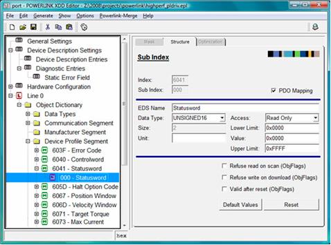
XDD file introduction
In POWERLINK, the XDD file is an extension of the CANopen Device Description File (Device Description File), which is used to describe the object dictionary structure, parameters and description information, device manufacturer information, etc. of the POWERLINK device. In POWERLINK, XDD files are usually provided by device manufacturers, and developers need to obtain them from device manufacturers.
How to make an XDD file
Steps to make an XDD file:
1. Determine the object dictionary: Determine the object dictionary of the device according to the specification or actual configuration of the device, and define it in the XDD file.
2. Add object parameters: define objects, parameters and their description information in the object dictionary. You can specify the type, unit, access rights, default value, etc. of the parameter.
3. Fill in the device description information: Add device description information, including device model, manufacturer information, device version number, etc.
4. Editing with an XML editor or CANopen Toolbox: Use the appropriate tool to edit and create the XDD file.
5. Verify and test the XDD file: Use the CANopen toolbox or other tools to verify and test to ensure that the format of the XDD file is correct and error-free.
The above are the basic steps for making XDD files.
In short, the XDD file is an extension of the CANopen device description file, which is used in POWERLINK to describe the object dictionary structure, parameters and description information, manufacturer information, etc. of the device.
XDD files are usually provided by device manufacturers. If you are a developer, you can also create them manually, or use tools to create them easily.
To make an XDD file, you need to determine the object dictionary, fill in parameters and description information, add device description information, etc. XDD files can be created and edited using various existing XML editors or the CANopen toolbox, with tools for verification and testing. Using the openCONFIGURATOR tool, creating a project will provide a default xdd file to be loaded, which can be used for manual modification. If you find it troublesome to modify manually, you can use tools. It can be edited with third-party tools, such as CANopen Magic, CANeds, etc. These tools all support CANopen information and parameter description, and can easily edit and manage XDD description files caneds3.6.92 tool download:
Introduction to tools for making XDD files
For previous generations of POWERLINK devices, although the EDS file based on CANopen has been able to meet the needs, XDD has become the current standardized file. port, a specialist in CAN- and Ethernet-based fieldbus systems, can now offer dedicated configuration tools designed for Windows and Linux operating systems, which greatly facilitate the generation of XDD files.
But helplessly, these tools are still charged. Introduction to other tools: Toolkit
In the CAN /CANopen product development process, configuring the object dictionary is a very important part. Users need to know enough about the CANopen protocol to know the possible variables and transmission types in the device. It is also necessary to ensure that the relevant definitions of the CANopen protocol are not violated during the design process. The process of designing the object dictionary often takes a long time, is prone to mistakes, or reworks because it does not meet expectations, or needs to design multiple functions and repeat work many times. When configuring the object dictionary, a professional and efficient CANopen design tool is needed. CANopen DeviceDesigner can not only help in the design, but also generate the code suitable for the object dictionary definition part of the emotas protocol stack according to the object dictionary.
The following tools are recommended
Ethernet POWERLINK XDD Tool Suite: Provides eclipse plug-ins for XDD editing, verification and OD generation. Download address: Find out more about Ethernet POWERLINK XDD Tool Suite | SourceForge.net
Eclipse download
Since the latest configuration tools openCONFIGURATOR and XDD editor of the master and slave stations are based on Eclipse, Eclipse needs to be downloaded and installed. It is recommended to install Eclipse IDE for Eclipse Committers after 4.x
Official website download: Eclipse Packaging Project (EPP) Releases | Eclipse Packages
Domestic image download address: Index of /eclipse/technology/epp/downloads/release/ .
other resources
(2) PowerLink theoretical knowledge_ty_xiumud's blog-CSDN blog
CANOPEN usage experience 1-cia301, cia402 brief summary_Jomb's Blog-CSDN Blog