TIM encoder interface
Before we dealt with the rotary encoder, it was interrupted once when it was rotated, which consumed resources.
We can use the encoder function of TIM to take the value of the rotator at intervals to make cnt++ or –, so as to judge the rotation position and calculation speed, which saves resources compared to interrupts. It is equivalent to connecting an external clock with direction.
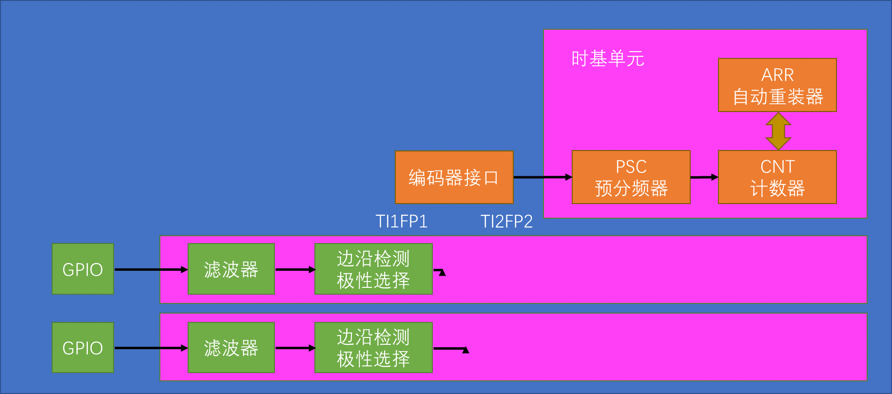
The encoder can receive the quadrature encoder signal to control the self-increment and self-decrement of cnt.

By judging the rising/falling edge of one of the phases, the other phase is high or low to determine the direction of rotation.
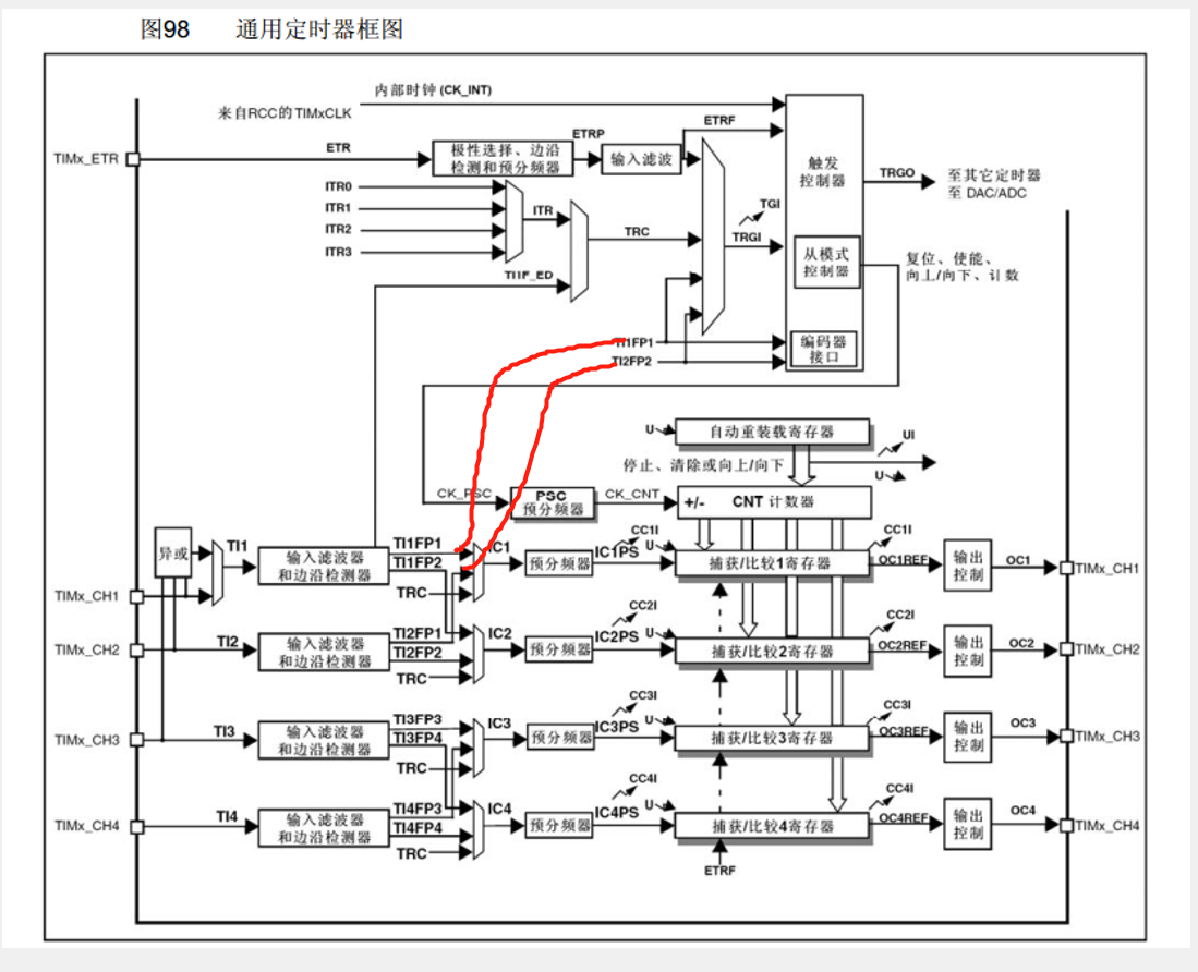
Encoder interface judgment is positive and negative, control cnt++ or –. arr is set to 65535, so that when cnt=0, it will become 65535 when it is decremented, and it will be -1 when it is converted into a signed number.
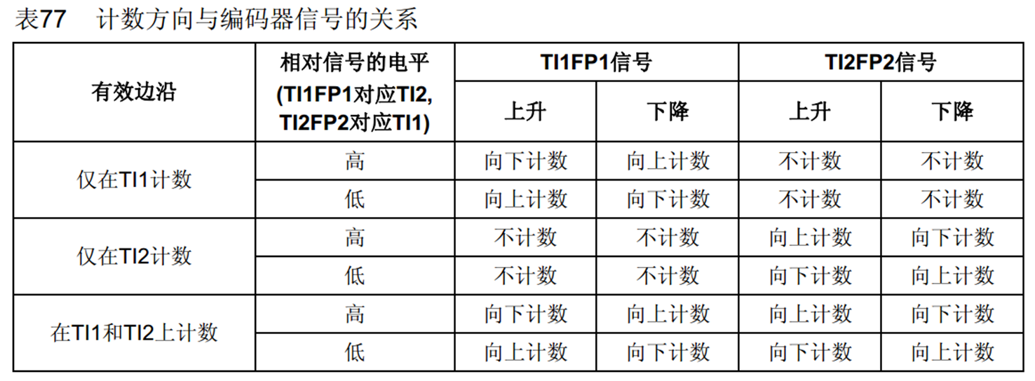
The last one is commonly used and has high precision.
The content here is the judgment corresponding to the AB phase. For example, in the figure, FP1 rises to FP2 high level, if 1 is A phase and 2 is B phase, that is, when A is rising, B is at high level, which corresponds to inversion, so it counts down.
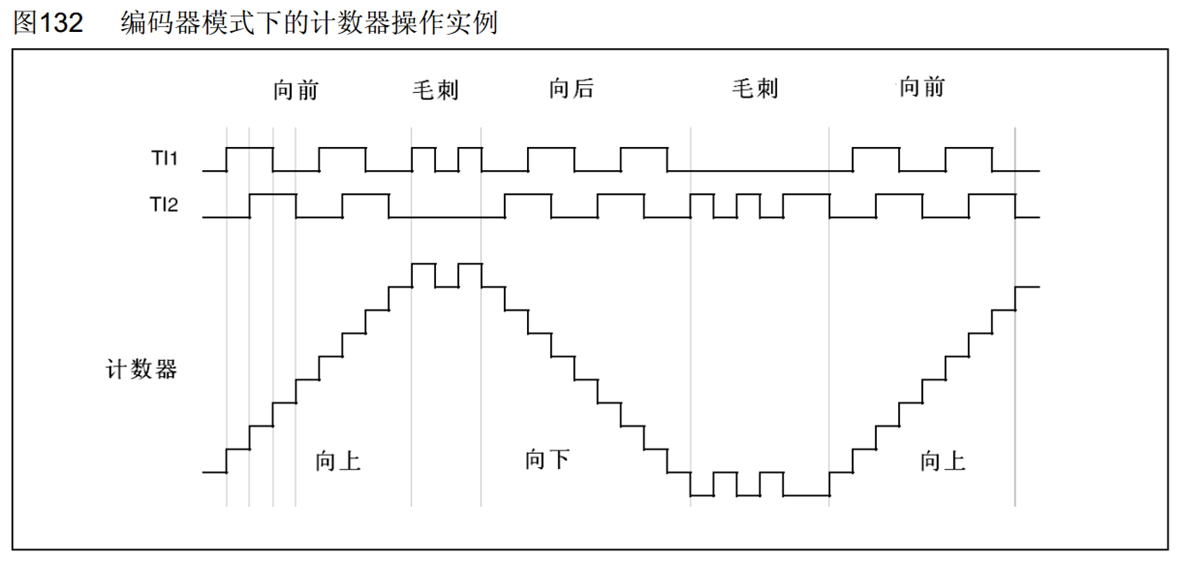
If one signal transitions, the other signal state is the same as the last transition, indicating a glitch. The count value swings back and forth to filter noise.
Code: Timer-based tachable encoder
Most are still IC-based codes. New function: TIM_EncoderInterfaceConfig, configures the encoder interface.
#include "stm32f10x.h"

void Encoder_Init(){


    //rcc, gpio, time base, ic(只配置滤波器和极性), TIM_Cmd 启动
    RCC_APB1PeriphClockCmd(RCC_APB1Periph_TIM3, ENABLE);
    RCC_APB2PeriphClockCmd(RCC_APB2Periph_GPIOA, ENABLE);
    GPIO_InitTypeDef GPIO_InitStructure;
    GPIO_InitStructure.GPIO_Mode=GPIO_Mode_IPU;
    GPIO_InitStructure.GPIO_Pin=GPIO_Pin_6|GPIO_Pin_7;
    GPIO_InitStructure.GPIO_Speed=GPIO_Speed_50MHz;
    GPIO_Init(GPIOA, &GPIO_InitStructure);

    TIM_TimeBaseInitTypeDef TIM_TimeBaseInitStructure;
    TIM_TimeBaseInitStructure.TIM_ClockDivision=TIM_CKD_DIV1;//滤波器采样,频率越低,采样点数越多,滤波效果越好。不过延迟也越大。采样频率就是内部时钟和这个分频参数共同作用的结果
    TIM_TimeBaseInitStructure.TIM_CounterMode=TIM_CounterMode_Up;
    //比如我们想定1s中断一次,CK_CNT_OV = CK_CNT / (ARR + 1) = CK_PSC / (PSC + 1) / (ARR + 1),也就是72M / (PSC + 1) / (ARR + 1) = 1
    //所以两者赋值可以是10000-1和7200-1,只要两者都在65535以内就行,赋值不唯一
    TIM_TimeBaseInitStructure.TIM_Period=65536-1;
    TIM_TimeBaseInitStructure.TIM_Prescaler=1-1;//预分频器值,不分频
    TIM_TimeBaseInitStructure.TIM_RepetitionCounter=0;//重复计数器值,高级计数器才用
    TIM_TimeBaseInit(TIM3, &TIM_TimeBaseInitStructure);

    //PA6 7对应定时器3,oc channel1 channel2.
    TIM_ICInitTypeDef TIM_ICInitStructure;
    TIM_ICStructInit(&TIM_ICInitStructure);
    TIM_ICInitStructure.TIM_Channel=TIM_Channel_1;//PA6对应定时器3 ch1
    //TIM_ICInitStructure.TIM_ICPolarity=TIM_ICPolarity_Rising;//下面一行配置的极性会覆盖上面的配置,所以这里不用写
    TIM_ICInitStructure.TIM_ICFilter=0xF;//滤波消除毛刺,越大效果越好,看需求
    TIM_PWMIConfig(TIM3, &TIM_ICInitStructure);
    TIM_ICInitStructure.TIM_Channel=TIM_Channel_2;//PA7对应定时器3 ch2
    //TIM_ICInitStructure.TIM_ICPolarity=TIM_ICPolarity_Rising;
    TIM_ICInitStructure.TIM_ICFilter=0xF;//滤波消除毛刺,越大效果越好,看需求
    TIM_PWMIConfig(TIM3, &TIM_ICInitStructure);

    TIM_EncoderInterfaceConfig(TIM3, TIM_EncoderMode_TI12,TIM_ICPolarity_Rising,TIM_ICPolarity_Rising);

    TIM_Cmd(TIM3, ENABLE);
}

uint16_t Encoder_Get(){


    return TIM_GetCounter(TIM3);
}
Because of turning one grid, AB each has a falling edge and a rising edge, so ±4.
If you want to measure the speed, you can manually clear it after getting it in the get function, and add a delay to get it in the main, such as once every 1000ms.
while(1){
        OLED_ShowNum(4,1,Encoder_Get(),5);
        Delay_ms(1000);
}
However, writing the delay in the main function will affect the operation of other parts of the program, so it is best to write an interrupt function.
void TIM2_IRQHandler(void){


    if(TIM_GetITStatus(TIM2,TIM_IT_Update)==SET){


        cnt=Encoder_Get();
        TIM_ClearITPendingBit(TIM2,TIM_IT_Update);
    }
}