[Graduation project] 8-Design and implementation of water quality/turbidity detector based on STM32 (schematic + source code + physical photos + answer essay)
Article Directory
mission statement
Main contents:
1. With STM32 microcontroller as the core, cooperate with water quality module;
2. Mainly complete the system's function control, status display, information detection, and the selection of components such as single-chip microcomputers and sensors required for the construction of alarm hardware;
3. Complete the software design and programming of system control;
4. Realize the functions of water quality detection, temperature inspection and early warning.
Methods and requirements:
system scheme and overall design: the main content of the design is to complete the drawing of the module circuit diagram and circuit board, complete the writing of the corresponding program, realize the transmission of remote data, and complete the control software design and the drawing and design of the circuit drawing. Contains:
1. Determination of the overall plan; 2. 3. The choice of hardware; Design of each module circuit; 4. Design of software part; 5. Debugging and running;
data link
原理图工程文件
PCB工程文件
源码工程文件
实物照片
答辩论文低重复率,23035字
design manual
Summary
Quality testing technology and development and application all involve sensor technology, electrical control technology and intelligent control technology. Intelligent control technology is a comprehensive technical subject, and it has become more and more extensive in the field of contemporary research control. In this design a water quality testing equipment. This design needs to realize the selection of components such as single-chip microcomputer and sensors required for the main completion of the system's energy control, status display, information detection, and alarm hardware; complete the software design and programming of the system control; realize the water quality detection, temperature detection, and early warning. Function. It is necessary to design the system function planning system to complete the hardware circuit part, software programming part, welding assembly part, debugging and testing part of the system, and finally complete the research and design of this paper.
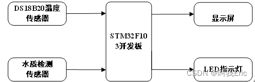
This system is mainly composed of hardware and software. The hardware part consists of the smallest system unit of STM32 single-chip microcomputer, temperature detection circuit unit, water quality detection unit and alarm unit, human-computer interaction unit, power supply unit, and liquid crystal display unit. The stability and reliability of the system need to be considered in the design of the hardware. The software part draws the overall flow chart of the system software, and draws each sub-control driver, and then writes the driver program to complete the design of the system program. In the design of hardware and software, we choose to design according to functional partitions, so that the design can be organized and run reliably. The system design and fabrication of physical objects are completed. Finally, the temperature detection and water turbidity detection are completed, and the threshold value can be adjusted to realize the customized alarm setting of the system to prevent false alarms.
When the system is designed, the overall cost performance and functionality of the system are fully considered. After the functions are completed, functional interfaces are reserved to expand the system functions. And this design keeps up with the trend of social development, and has promotional significance in relation to the health care industry.
Design framework
Preface 1
Chapter 1 Introduction 2
Section 1 Research Background 2
Section 2 Research Significance 3
Section 3 National Water Quality Standard 3
Section 4 Introduction to Sensor Development 4
Section 5 Main Research Contents of this Paper 7
Section 6 Summary of this Chapter 8
Second Chapter Water Quality Detection System Scheme 9
Section 1 System Implementation Function Analysis 9
Section 2 System Design Ideas 9
Section 3 Main Controller Selection 10
Section 4 Main Components Introduction 10
1. Water Quality Detection Module 11
2. Temperature Sensor
13 Chapter 5 Summary of this Chapter 15
Chapter 3 Water Quality Detection Hardware Circuit Design 16
Section 1 STM32 Minimum System Board Introduction 16
Section 2 Power Circuit Design 17
Section 3 Water Quality Detection Circuit Design 18
Section 4 Temperature Sensor Circuit Design 19
Section 5 OLED Display circuit design 20
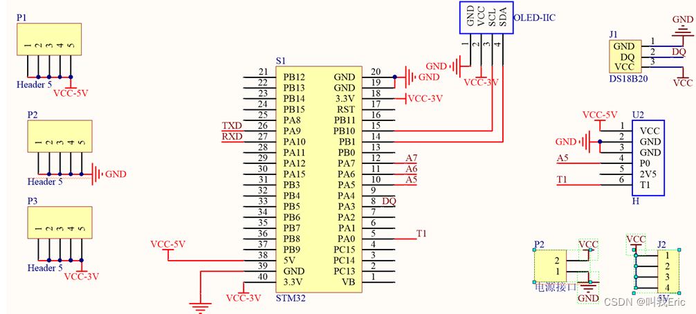
Section 6 System general circuit diagram 21
Section 7 Summary of this chapter 22
Chapter 4 Water quality testing software design 23
Section 1 Keil MDK software introduction 23
Section 2 Software main program design 24
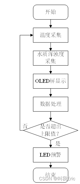
1. Main program design process 24
2. Main program source code 25
Section 3 OLED display program design 26
1. OLED display program flow 26
2. OLED display program source code 28
Section 4 Water quality testing program design 29
1. Water quality testing program flow 29
2. Water quality testing program source code 31
Section 5 Temperature testing program design 32
1. Temperature testing program flow 32
2. Temperature testing Program source code 33
Section 6 Summary of this chapter 34
Chapter 5 Implementation of water quality detection system 35
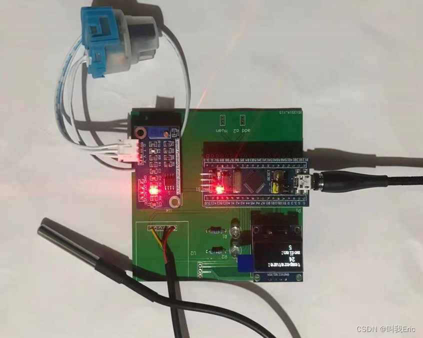
Section 1 Physical welding and debugging 35
Section 2 System function test 37
1. Water quality detection function test 37
2. Temperature detection test 38
Section 3 Summary of this chapter 40
Summary 41
Acknowledgments 42
References 43 Appendix
45
1. Original English text 45
2. English translation 48
3. Engineering drawings 51
4. Source code 52
Design instructions and design documents
Word count: 23035 words
Source code display
#include "delay.h"
#include "sys.h"
#include "oled.h"
#include "led.h"
#include "usart.h"
#include "adc.h"
#include "ds18b20.h"
#include "temp.h"
#include "timer.h"
#define ARRY_LENGTH 10
#define median_filtering_length 3
float num[2];16 median_filtering(void);
 int main(void)
  {
		float temperature;      //温度值
		float hui;         //H2采集的数字量

		delay_init();	    	 //延时函数初始化
		NVIC_Configuration();//设置NVIC中断分组2:2位抢占优先级,2位响应优先级
		Adc_Init();	         //AD初始化
		uart_init(9600);	   //串口初始化
    Timer4_Init(4999,7199);
		OLED_Init();			   //初始化OLED
		OLED_Clear(); 	     //Clear screen
		LED_Init();
 	while(DS18B20_Init())	//DS18B20初始化
	{
		OLED_ShowString(0,0,"DS18B20 Error",16);	//初始化失败,检查连线
		delay_ms(200);														//延时等待数据稳定
	}
		OLED_Clear(); 	     											//清屏

	while(1)
	{
		OLED_ShowString(0,0,"temperature:",16);
		temperature=DS18B20_Get_Temp();						//采集温度
		temperature=temperature/10;
		OLED_ShowNum(0,2,temperature,4,16);  			//显示温度
	  printf("温度:%d  \r\n",(int)temperature);
		if(temperature>25){LED2=0;}
		else LED2=1;
		hui=median_filtering();
	 	hui=hui*(3.3/4096);
		hui = hui*100/3.3;
		if(hui > 100) hui = 100;
		hui=100-hui;
		OLED_ShowString(0,4,"median:",16);
	 OLED_ShowNum(0,6,hui,4,16);  			//显示浑浊度
	 printf("浑浊度:%d  \r\n",(int)hui);
	 if(hui>41)LED3=0;
	 else LED3=1;
	}
}
u16 median_filtering(){
  int senseV[median_filtering_length];
  int i,k;
  for(i = 0; i < median_filtering_length; i++){
    senseV[i] = Get_Adc_Average(6,5);
		delay_ms(3);
  }
  for(i = 0; i < median_filtering_length; i++ ){
    for(k = i; k <median_filtering_length; k++ ){
      if(senseV[i] > senseV[k]){
          int tmp = senseV[i];
          senseV[i] = senseV[k];
          senseV[k] = tmp;
      }
    }
  }
  return senseV[median_filtering_length/2];
}
#include "ds18b20.h"
#include "delay.h"
//复位DS18B20
void DS18B20_Rst(void)
{
	DS18B20_IO_OUT(); //SET PA0 OUTPUT
    DS18B20_DQ_OUT=0; //拉低DQ
    delay_us(750);    //拉低750us
    DS18B20_DQ_OUT=1; //DQ=1
	delay_us(15);     //15US
}
//等待DS18B20的回应
//返回1:未检测到DS18B20的存在
//返回0:存在
u8 DS18B20_Check(void)
{
	u8 retry=0;
	DS18B20_IO_IN();//SET PA0 INPUT
    while (DS18B20_DQ_IN&&retry<200)
	{
		retry++;
		delay_us(1);
	};
	if(retry>=200)return 1;
	else retry=0;
    while (!DS18B20_DQ_IN&&retry<240)
	{
		retry++;
		delay_us(1);
	};
	if(retry>=240)return 1;
	return 0;
}
//从DS18B20读取一个位
//返回值:1/0
u8 DS18B20_Read_Bit(void) 			 // read one bit
{
    u8 data;
	DS18B20_IO_OUT();//SET PA0 OUTPUT
    DS18B20_DQ_OUT=0;
	delay_us(2);
    DS18B20_DQ_OUT=1;
	DS18B20_IO_IN();//SET PA0 INPUT
	delay_us(12);
	if(DS18B20_DQ_IN)data=1;
    else data=0;
    delay_us(50);
    return data;
}
//从DS18B20读取一个字节
//返回值:读到的数据
u8 DS18B20_Read_Byte(void)    // read one byte
{
    u8 i,j,dat;
    dat=0;
	for (i=1;i<=8;i++)
	{
        j=DS18B20_Read_Bit();
        dat=(j<<7)|(dat>>1);
    }
    return dat;
}
//写一个字节到DS18B20
//dat:要写入的字节
void DS18B20_Write_Byte(u8 dat)
 {
    u8 j;
    u8 testb;
	DS18B20_IO_OUT();//SET PA0 OUTPUT;
    for (j=1;j<=8;j++)
	{
        testb=dat&0x01;
        dat=dat>>1;
        if (testb)
        {
            DS18B20_DQ_OUT=0;// Write 1
            delay_us(2);
            DS18B20_DQ_OUT=1;
            delay_us(60);
        }
        else
        {
            DS18B20_DQ_OUT=0;// Write 0
            delay_us(60);
            DS18B20_DQ_OUT=1;
            delay_us(2);
        }
    }
}
//开始温度转换
void DS18B20_Start(void)// ds1820 start convert
{
    DS18B20_Rst();
	DS18B20_Check();
    DS18B20_Write_Byte(0xcc);// skip rom
    DS18B20_Write_Byte(0x44);// convert
}
//初始化DS18B20的IO口 DQ 同时检测DS的存在
//返回1:不存在
//返回0:存在
u8 DS18B20_Init(void)
{
 	GPIO_InitTypeDef  GPIO_InitStructure;

 	RCC_APB2PeriphClockCmd(RCC_APB2Periph_GPIOA, ENABLE);	 //使能PORTG口时钟

 	GPIO_InitStructure.GPIO_Pin = GPIO_Pin_0;				//PORTG.11 推挽输出
 	GPIO_InitStructure.GPIO_Mode = GPIO_Mode_Out_PP;
 	GPIO_InitStructure.GPIO_Speed = GPIO_Speed_50MHz;
 	GPIO_Init(GPIOA, &GPIO_InitStructure);
 	GPIO_SetBits(GPIOA,GPIO_Pin_0);    //输出1
	DS18B20_Rst();
	return DS18B20_Check();
}
//从ds18b20得到温度值
//精度:0.1C
//返回值:温度值 (-550~1250)
short DS18B20_Get_Temp(void)
{
    u8 temp;
    u8 TL,TH;
	short tem;
    DS18B20_Start ();                    // ds1820 start convert
    DS18B20_Rst();
    DS18B20_Check();
    DS18B20_Write_Byte(0xcc);// skip rom
    DS18B20_Write_Byte(0xbe);// convert
    TL=DS18B20_Read_Byte(); // LSB
    TH=DS18B20_Read_Byte(); // MSB
    if(TH>7)
    {
        TH=~TH;
        TL=~TL;
        temp=0;//温度为负
    }else temp=1;//温度为正
    tem=TH; //获得高八位
    tem<<=8;
    tem+=TL;//获得底八位
    tem=(float)tem*0.625;//转换
	if(temp)return tem; //返回温度值
	else return -tem;
}