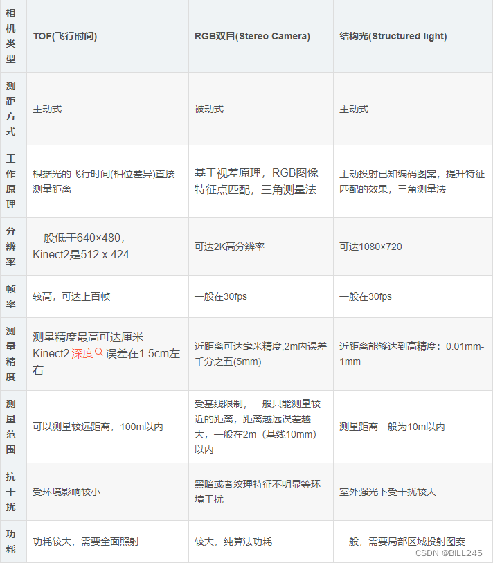
Although this article is named as a comparison document, there are still many contents that are not particularly meaningful in comparison—such as the errors of the three 3D technologies—in other words, this article aims to compare the characteristics and characteristics of the three 3D technologies. Summarize. The information is mainly from the Internet, and some relevant references will be attached at the end of the article. Due to limited time, some pictures have multiple watermarks, if there is any infringement, please contact the author to delete. The author's study time is about one week, and there are many literatures and Internet materials to browse, so there are inevitably gaps in the references. This article is the author's learning summary and is used for personal learning records. If readers have any insights, please feel free to enlighten me.
Table of contents
1. Overview of three 3D technologies
2. Components of three 3D technologies
2.2 Dual-purpose computing process
3. Principle comparison of three 3D technologies
3.1.2 iToF (continuous wave modulation)
3.3.2.1 De Bruijn sequence (De Bruijn) sequence
3.3.2.2 Two-dimensional spatial encoding
4. Errors of the three 3D technologies
5. Advantages and disadvantages of three 3D technologies
5.1.1 Direct measurement method
5.1.2 Indirect measurement method
7.2 Dual-purpose partial references
7.3 Some reference materials of structured light
7.4 Some references for the comparison of three 3D technologies
1. Overview of three 3D technologies
1.1 ToF
ToF (Time of flight), that is, the time of flight method, is a method of depth measurement with an accuracy of centimeters. The principle of ToF is simple, the module is small in size, the measurement distance range is large, and the anti-interference ability is strong. The ToF ranging method belongs to the two-way ranging technology, which mainly uses the flight time of the signal to and fro between two asynchronous transceivers (Transceiver) (or reflected surface) to measure the distance between nodes.
According to different modulation methods, ToF can be divided into two types: Pulsed Modulation and Continuous Wave Modulation. Pulse modulation measures the time of flight directly, so it is also called dToF (direct); continuous wave modulation calculates the time of flight through phase difference, so it is also called iToF (indirect).
1.2 Binocular
Binocular stereo vision (Binocular Stereo Vision) is an important form of machine vision. It is based on the principle of parallax and uses imaging equipment to obtain two images of the measured object from different positions. By calculating the position deviation between corresponding points of the image, A method to obtain the three-dimensional geometric information of the object.
Binocular stereo vision combines the images obtained by the two eyes and observes the differences between them, so that we can obtain a clear sense of depth, establish the correspondence between features, and correspond to the image points of the same physical point in different images. This difference is called a disparity image.
The binocular stereo vision measurement method has the advantages of high efficiency, appropriate accuracy, simple system structure, and low cost, and is very suitable for on-line, non-contact product inspection and quality control at the manufacturing site. In the measurement of moving objects (including animals and human body), the stereo vision method is a more effective measurement method because the image acquisition is completed in an instant. The binocular stereo vision system is one of the key technologies of computer vision, and obtaining the distance information of the spatial three-dimensional scene is also the most basic content in computer vision research.
1.3 Structured light
Structured light technology is to use pre-designed patterns with special structures (such as discrete light spots, streaked light, coded structured light, etc.), and then project the pattern onto the surface of a three-dimensional space object, and use another camera to observe the imaging on the three-dimensional physical surface . distortion. If the structured light pattern is projected on the surface of the object as a plane, then the observed structured light pattern in the imaging is similar to the projected pattern, without deformation, but with a certain scale change according to the distance. However, if the surface of the object is not flat, the observed structured light pattern will be distorted differently due to the different geometric shapes of the object surface, and it will be different according to the distance. According to the known structured light pattern and the observed Deformation, the three-dimensional shape and depth information of the measured object can be calculated according to the algorithm.
Generally speaking, structured light can be divided into line-scan structured light and area array structured light, and the former will not be discussed in this article. For area structured light, it can be roughly divided into two categories: random structured light and coded structured light. Random structured light is simpler and more commonly used. The projector projects point-like structured light with uneven brightness and random distribution into the measured space, and the binocular image is imaged by the binocular camera. The resulting binocular image is corrected by the epipolar line and then subjected to binocular dense matching to reconstruct the corresponding depth map. Random structured light is not discussed in this article , because it is similar to the ordinary binocular algorithm . Some additional considerations are hardware and optical issues such as whether to add a filter to the camera, how high the spot density should be, and so on.
Here we mainly discuss coded structured light. Coded structured light can be divided into two categories: temporal coded and spatially coded.
2. Components of three 3D technologies
Due to the development and innovation of technology, it is difficult for us to rigidly frame the components of the three 3D technologies. This section is only for reference to understand the three technologies.
2.1 ToF
TOF cameras use active light detection and usually include the following parts:
1. Irradiation unit
The irradiation unit needs to pulse modulate the light source before emitting, and the modulated light pulse frequency can be as high as 100MHz. As a result, the light source is turned on and off thousands of times during image capture. Each light pulse is only a few nanoseconds long. The camera's exposure time parameter determines the number of pulses per image.
To achieve accurate measurements, the light pulses must be precisely controlled to have exactly the same duration, rise time, and fall time. Because even a deviation of only 1 ns can produce a distance measurement error of up to 15 cm. Such a high modulation frequency and precision can only be achieved by using sophisticated LEDs or laser diodes. Generally, the irradiation light source is an infrared light source that is invisible to the human eye.
2. Optical lens
It is used to gather reflected light and form an image on an optical sensor. However, unlike ordinary optical lenses, a bandpass filter needs to be added here to ensure that only light with the same wavelength as the illumination source can enter. The purpose of this is to suppress incoherent light sources, reduce noise and prevent the photosensitive sensor from being overexposed to external light interference.
3. Imaging sensor
The core of the TOF camera. The structure of the sensor is similar to that of an ordinary image sensor, but it is more complex than an image sensor. It contains 2 or more shutters to sample reflected light at different times. Therefore, the pixel size of the TOF chip is much larger than that of the general image sensor, generally about 100 μm.
4. Control unit
The sequence of light pulses triggered by the camera's electronic control unit is precisely synchronized with the opening/closing of the chip's electronic shutter. It performs readout and conversion of the sensor charges and directs them to the analysis unit and data interface.
5. Calculation unit
The computing unit can record precise depth maps. A depth map is usually a grayscale image, where each value represents the distance between the light-reflecting surface and the camera. In order to get better results, data calibration is usually performed.
2.2 Dual-purpose computing process
Due to the distinction between active binoculars and passive binoculars, the composition of binoculars is different. For example, the active infrared binocular includes an IR projector and an IR camera, and the passive binocular includes two visible light cameras, etc. (in fact, the active binocular can be regarded as a combination of traditional passive binocular and structured light). The following is a brief introduction to the calculation process of binocular stereo vision.
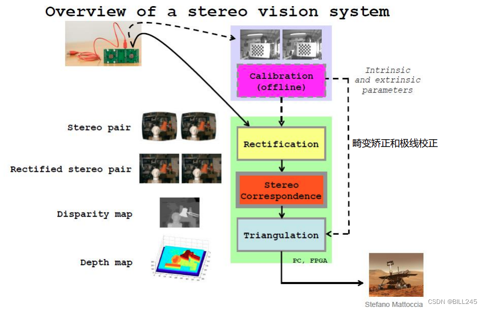
Figure 2.1 Flow chart of binocular calculation
As shown in Figure 2.1, first obtain the internal and external parameters of the camera through dual-target calibration (calibrate the internal parameters of the two cameras and the external parameters between the two cameras), after calibration (including distortion correction and epipolar correction, in the process of consulting data It is found that correction and correction are often replaced, but in "Learning OpenCV" P430 page, there is such an explanation: distinguish between "correction undistortion" and "correction rectification". Correction: remove lens distortion mathematically. Correction: mathematically transform the image Orderly rows.
I personally think that rectification means "removing or correcting the wrong", and rectification means "rearranging the chaos or making it orderly through calculation". ) After binocular positioning, we get the pose relationship between the two cameras, namely the rotation matrix R and the translation matrix T. Before performing stereo matching, the most core step of binocular 3D vision, through epipolar correction, we usually adjust two non-coplanar cameras into coplanar alignment through stereo correction, that is, adjust the imaging planes of the two cameras To the same plane, ensure that each row of the two auxiliary images is corresponding. This will turn the two-dimensional search problem into a one-dimensional search problem, so when looking for the matching relationship, you only need to search on the same line of the two images, and at the same time, the problem of solving the depth can be transformed into the problem of solving the parallax . Then by solving the difference of the abscissa of the same point on the two images, the depth of this point in the real space is determined. The most common correction method is the Bouguet correction algorithm: decompose the calibrated external parameter matrices R and T into the rotation and translation matrices R1, T1 and R2, T2 of the left and right cameras that rotate half each. The principle of decomposition is that the distortion caused by the reprojection of the left and right images is the smallest, and the common viewing area of the left and right views is the largest, as shown in Figure 2.2.
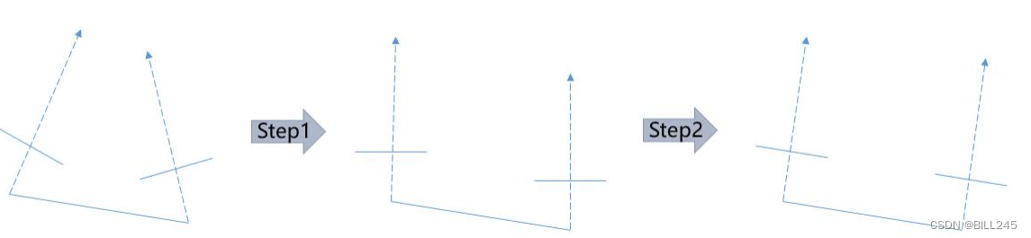
Figure 2.2 Schematic diagram of Bouguet algorithm
After correction, it is stereo matching. Stereo matching uses a camera with known external parameters to find the same-named point in the real space according to the epipolar constraints, and then estimates the depth of the point in this space. Stereo matching includes matching cost calculation, cost aggregation, disparity calculation and disparity optimization/post-processing.
See Figure 2.3 and Figure 2.4 for information about stereo matching (picture articles, etc.).
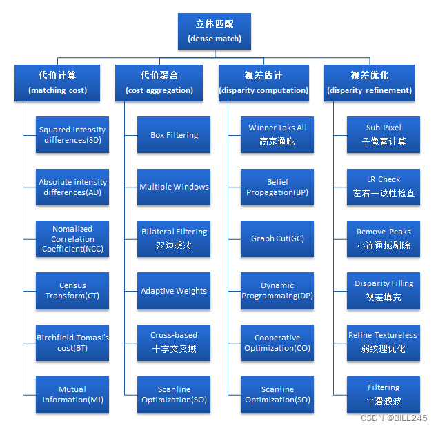
Figure 2.3 Four parts of stereo matching
Figure 2.4 Classification of stereo matching
The relevant knowledge of stereo matching is sorted out in considerable detail in the following blog post:
Getting Started with Binocular Stereo Matching [1] (Theory)
2.3 Structured light
The whole system of 3D structured light includes structured light projection equipment, camera, image acquisition and processing system. The process is that the projection device emits light onto the measured object, the camera captures the three-dimensional light pattern formed on the measured object, and the captured image is processed by the acquisition and processing system to obtain the surface data of the measured object. In this system, when the relative position of the camera and the projection device is constant, the degree of distortion of the light projected on the measured object depends on the depth of the surface of the object, so a light image with depth can be obtained in the captured image.
The essence of 3D structured light is to obtain the three-dimensional structure of the object to be photographed by optical means, and then use this information for more in-depth applications.
3. Principle comparison of three 3D technologies
3.1 ToF
The basic principle of ToF is to continuously emit light pulses (generally invisible light) to the measured object, and then receive the light pulses reflected back from the object, and calculate the distance between the measured object and the camera by detecting the flight (round trip) time of the light pulse. distance.
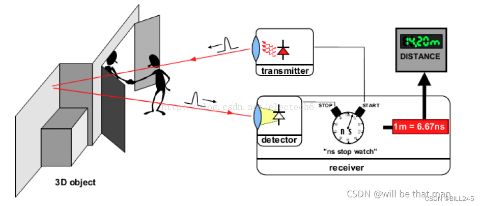
Figure 3.1 Schematic diagram of the basic principle of time-of-flight depth measurement
The principle of ToF will be introduced respectively according to the two types of ToF.
3.1.1 dToF (pulse modulation)
Pulse modulation measures distance directly from the time difference between pulse transmission and reception. Figure 3.2 is a schematic diagram of pulse modulation ranging:
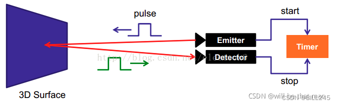
Figure 3.2 Schematic diagram of pulse modulation ranging
The illumination light source of the pulse modulation scheme generally adopts square wave pulse modulation, this is because it is relatively easy to realize with digital circuit. Each pixel at the receiving end is composed of a photosensitive unit (such as a photodiode), which can convert incident light into current. The photosensitive unit is connected to multiple high-frequency switches (G0, G1 in the figure below) to guide the current into different In the capacitor that can store charge (Figure 3.3S0, S1).
A control unit on the camera turns the light source on and off, sending out a pulse of light. At the same moment, the control unit opens and closes the electronic shutter at the receiving end. The charge received at the receiving end is stored in the photosensitive element.
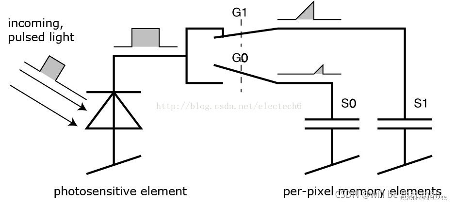
Figure 3.3 Receiver unit circuit diagram
Then, the control unit switches the light source on and off a second time. This time the shutter is opened later, that is, at the time when the light source is turned off, and the newly received charge S1 is also stored. The specific process is shown in Figure 3.4.
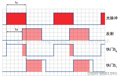
Figure 3.4 Pulse waveform diagram
Because the duration of a single light pulse is so short, this process is repeated thousands of times until the exposure time is reached. The values in the light sensor are then read and the actual distance can be calculated from these values.
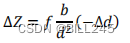
Note that the speed of light is c, tp is the duration of the light pulse, S0 represents the charge collected by the earlier shutter, and S1 represents the charge collected by the delayed shutter, then the distance d can be calculated by the following formula:
The smallest measurable distance is: during the earlier shutter period S0 all charges are collected, and during the delayed shutter period S1 no charge is collected, ie S1=0. Substituting into the formula will give the minimum measurable distance d=0.
The largest measurable distance is where all charge is collected in S1 and no charge is collected at all in S0. The formula then yields d = 0.5 x c x tp. The maximum measurable distance is therefore determined by the light pulse width. For example, tp=50ns, substitute into the above formula to get the maximum measurement distance.
It should be noted that when the reflection time exceeds the duration of the light pulse, the above measurement method is useless. So we set the shutter S2 to solve this problem, as shown in Figure 3.5. And when the reflection time is within the light pulse duration, the shutter S2 can also test the influence of ambient light.
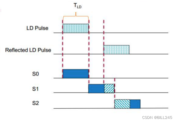
Figure 3.5 Direct measurement method
advantage:
The measurement method is simple and the response is fast;
Due to the high energy of the transmitting end, the interference of background light is reduced to a certain extent.
shortcoming:
The transmitter needs to generate high-frequency and high-intensity pulses, which have high requirements on the performance of physical devices;
Higher requirements for time measurement accuracy;
The ambient scattered light has a certain influence on the measurement results.
3.1.2 iToF (continuous wave modulation)
In practical Since the phase offset of the sine wave at the receiving end and the transmitting end is proportional to the distance of the object from the camera (see the derivation later), the phase offset can be used to measure the distance. Figure 3.6 is a schematic diagram of the principle of continuous wave modulation:
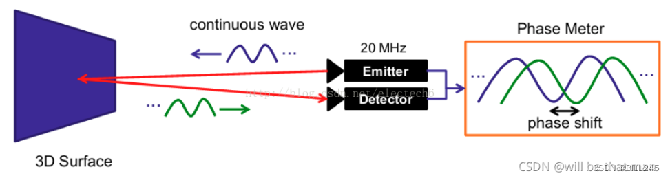
Figure 3.6 Schematic diagram of continuous wave modulation ranging
In fact, the method of measuring the distance phase difference by phase shifting is basically the same as the derivation of the four-step phase shifting method. The following figure is a schematic diagram of the transmitted sine wave and the received sine wave:
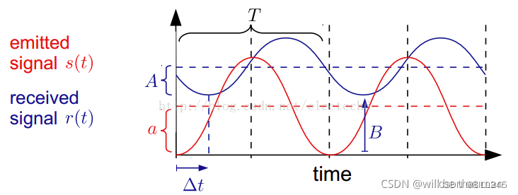
Figure 3.7 Schematic diagram of transmitting and receiving sine waves
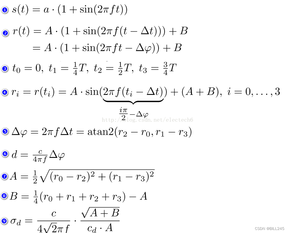
Continuous sine wave modulation measurement method, the specific derivation process is as follows. Numbers 1-9 correspond to formulas 1-9 in the figure below.
- Suppose the amplitude of the transmitted sinusoidal signal s(t) is a, and the modulation frequency is f
- The signal received after the time delay △t is received r(t), the amplitude after attenuation is A, and the intensity offset (caused by ambient light) is B
- The four sampling time intervals are equal, all are T/4
- According to the above sampling time, four equations can be listed
- Thus the phase offset △φ of the transmitted and received sinusoidal signals can be calculated
- According to this, the distance d between the object and the depth camera can be calculated according to the formula in 6
- Calculation result of the amplitude A after attenuation of the received signal
- Calculated result of received signal strength offset B, reflecting ambient light
- The values of A and B indirectly reflect the depth measurement accuracy, and the depth measurement variance can be approximated by Equation 9.
advantage:
(r2-r0) and (r1-r3) in the phase offset (Equation 5) eliminate fixed deviations due to measurement devices or ambient light relative to the pulse-tuning method;
The accuracy (variance) of the depth measurement results can be estimated indirectly according to the amplitude A and intensity offset B of the received signal;
It is not required that the light source must be a short-time high-intensity pulse, and different types of light sources and different modulation methods can be used.
shortcoming:
Multiple sampling integration is required, and the measurement time is long, which limits the frame rate of the camera;
Multiple sampling integration is required, and motion blur may occur when measuring moving objects.
3.2 Binocular
Before introducing binocular ranging, let's take a look at the general monocular camera model
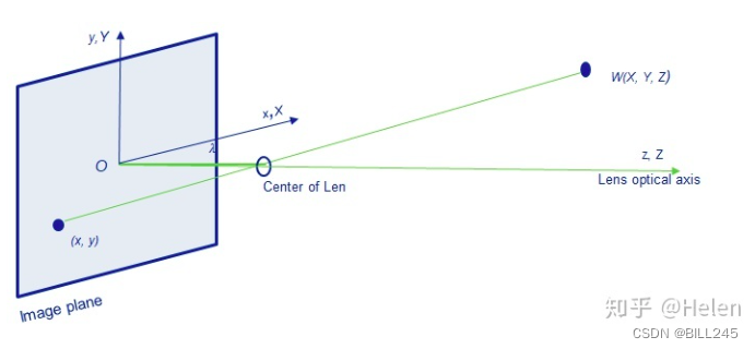
Figure 3.8 Schematic diagram of a general monocular camera model
In the general camera model, X, Y, Z are the world coordinate system, (x, y, z) is the camera coordinate system, according to the similarity of the x triangle:

Binocular ranging principle: triangulation/parallax principle
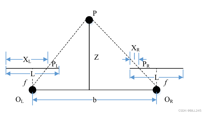
Figure 3.9 Schematic diagram of parallax
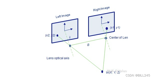
Figure 3.10 Schematic diagram of binocular ranging
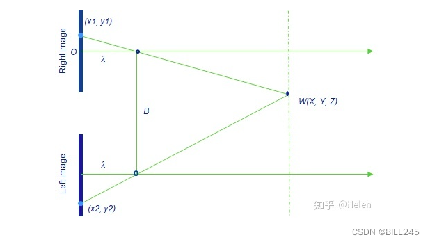
Figure 3.11 Schematic diagram of binocular ranging
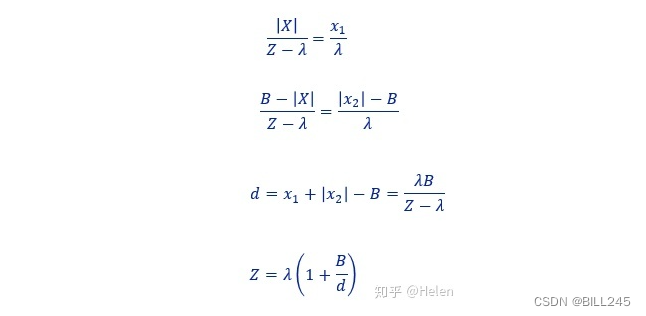
Depth Z is calculated as follows:
3.3 Structured light
3.3.1 Timing Encoding
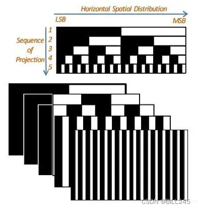
Figure 3.12 Schematic diagram of time sequence coding structured light
As shown in Figure 3.12 , the time-sequence coded structured light is to project a series of structured light with different brightness and darkness to the measured space through the projector within a certain time range, and each projection is imaged by the camera. Assume that there are n images in total, and set the encoding value of the part covered by the shadow to 1, and the encoding value of the part not covered is 0. At this point, each pixel corresponds to a unique binary code of length n, and the problem of searching for matching pixels in the binocular image becomes finding pixels with the same coded value. If the binocular image has been epipolar corrected, then the projected structured light only needs to be non-repeatable in the x direction.
As shown in Figure 3.13, the code of the pixels in the red frame is 0110, and it is 6 when converted to decimal. At this point, it is only necessary to retrieve the pixel with the coded value 6 on the same row in the right image. The encoding method in Figure 3.13 is called binary code (binary code), and each area is divided into two continuously until the coded width of the projection is equal to the pixel width of the camera. For an image with a width of 1024, at least 10 images are required for encoding.
(The coding of the three columns on the right in Figure 3.13 is wrong, it should be 0010, 0001, 0000)
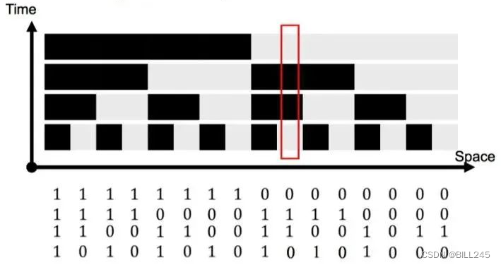
Figure 3.13 Coding conversion diagram
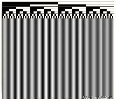
Figure 3.14 Binary Code
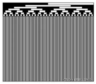
Figure 3.15 Gray Code
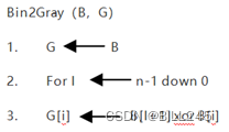
An improvement of Binary Code is Gray Code. Gray Code has better robustness than Binary Code, which makes the difference between two adjacent pixels 1bit. For a detailed introduction of Gray Code and the conversion between it and Binary Code, please refer to Wikipedia.
Pay attention to observation and you can see the difference between gray code and binary code in the first few lines of pixels
Conversion algorithm:
Naturally, besides the binary 0-1 encoding, more color-level encodings can also be used. Assuming that M different gray levels are used for encoding, the effect of M^N strips can be obtained by shooting N images. As shown in the figure below, when M = 3 and N = 3, there are 27 bands in the figure.
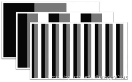
Figure 3.16 Two-dimensional encoding of three gray levels of three images
From the above introduction, the advantages and disadvantages of time-sequence coded structured light can also be obtained:
advantage:
High precision.
shortcoming:
Good for static scenes only; requires a lot of footage.
3.3.2 Spatial encoding
To meet the needs of dynamic scenes, spatially encoded structured light can be used. We talked about random structured light earlier, which means projecting random textures without coding information, but the spatially coded structured light discussed here refers to the projected mathematically coded, non-repetitive structured light within a certain range of light spots in the measured space. Thus, the code value of a certain point can be obtained through its neighborhood. Among them, the number of pixels (window size) that contains a complete spatial code determines the accuracy of the reconstruction.
3.3.2.1 De Bruijn sequence (De Bruijn) sequence
The De Bruin sequence (Wikipedia) B(k, n) means that k symbols (such as binary, k = 2) are used to represent a cyclic code of length , and n is the length of a coded value. Example: the simplest, when k = 2, use binary symbols (0, 1), and the length of the coded value n = 2, you can get a cyclic sequence of length: [0, 0, 1, 1]. At this point, we get 4 different codes of length 2: [0, 0], [0, 1], [1, 1], [1, 0]. Therefore, some kind of structured light can be coded according to the De Bruin sequence. In the obtained structured light image, the encoding of the above four pixels is [0, 0, 1, 1], which can be obtained through a sliding window of size 2 (assuming that the width of a structured light spot or beam is one pixel) An encoded value for each pixel. Similarly, if it is a binocular image that has undergone epipolar correction, you only need to search for the corresponding row. At this time, it is only required that the encoding is not repetitive on the x-axis. The structured light at this time is in the shape of vertical strips.
Of course, in order to improve coding efficiency, projection methods such as grayscale images and color images that have more possible coding values than 0-1 coding can also be used. For example, for RGB images, if binary encoding is used (that is, there are only two states for a certain color), there are a total of color combinations, and (0, 0, 0) is removed, and there are 7 colors left. Therefore, k = 7, n = 3, so that a strip sequence with a length of 343 can be obtained. For this sequence, the only constraint is that adjacent strips cannot be the same color. Otherwise, it is easy to cause errors for the decoding algorithm. The image below shows a structured light sequence using only 5 colors (k = 5, n = 3):
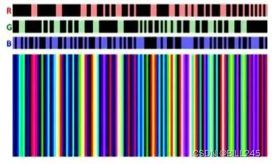
Figure 3.17 Structured light sequence of 5 colors
3.3.2.2 Two-dimensional spatial encoding
The De Bruin sequence is a one-dimensional code that can be extended to a two-dimensional space, so that for a two-dimensional space of x * y size, the coded value contained in a sub-window of w * h size is in this Appears only once in the entire 2D-coded sequence.
Figure 3.18 4 * 6M-arrays sequence
As in the 4 * 6 M-arrays sequence above, each 2 * 2 window contains unique encoding values.
Similarly, RGB information can also be used for two-dimensional encoding, and there are related algorithms to generate some pseudo-random two-dimensional encoding. As shown in the figure below, a 6*6 two-dimensional matrix is shown on the left, and the size of the sub-window is 3*3. The algorithm first randomly fills in various colors in the 3*3 sub-window in the upper left corner; then a 3*1 sliding window moves to the first blank space on the right, and randomly fills in 3 colors; after filling in the generated Before randomizing the color, the algorithm will first verify that the unique performance of the encoding of the sub-window cannot be guaranteed. If not, it will regenerate 3 random colors; in this way, the size of the sliding window in the vertical direction becomes 1 * 3, Until the entire 6*6 matrix is filled. The image on the right is an example of a pseudo-random 2-D code produced by the algorithm .
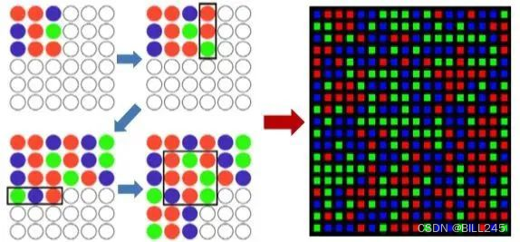
Figure 3.19 RGB two-dimensional coding
Through the above discussion of spatial coding, we can also see some advantages and disadvantages of spatial coding structured light:
advantage:
Instead of multiple photos, only one pair of images is needed for 3D reconstruction. It can satisfy real-time processing and be used in a dynamic environment.
shortcoming:
Susceptible to noise interference; due to reflections, lighting and other reasons, coding information such as some areas may be missing during imaging; it is sensitive to occlusion in space; compared with time-series coding structured light, the accuracy is lower.
4. Errors of the three 3D technologies
4.1 ToF
4.1.1 Systematic errors
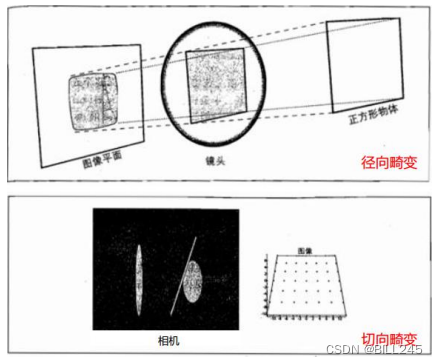
Figure 4.1 Schematic diagram of lens distortion
Lens distortion , including radial distortion and tangential distortion, wherein radial distortion comes from the shape of the lens, which can be further divided into pincushion distortion and barrel distortion according to the form of distortion; tangential distortion comes from the entire camera assembly process, For example, the lens is not very parallel to the sensor (generally, the tangential distortion is small).
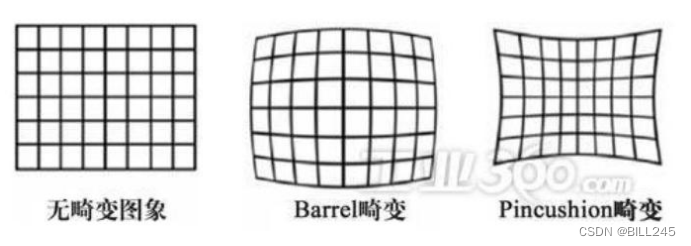
Figure 4.2 Schematic diagram of lens distortion
FPPN fixed phase pattern noise, also known as gradient error . The Sensors are arranged in arrays, which brings about a problem, that is, the time from the signal to the signal on each array is different, which leads to a certain amount of time delay between each Pixel. In addition, there is a certain time delay between the exposure and the reference signal, which will lead to an overall upward deviation. Therefore, FPPN is actually composed of two parts, the overall upward bias and the local difference between each Pixel.
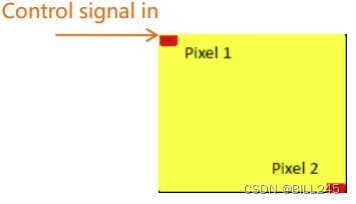
Figure 4.3 Schematic diagram of Sensor and Pixel
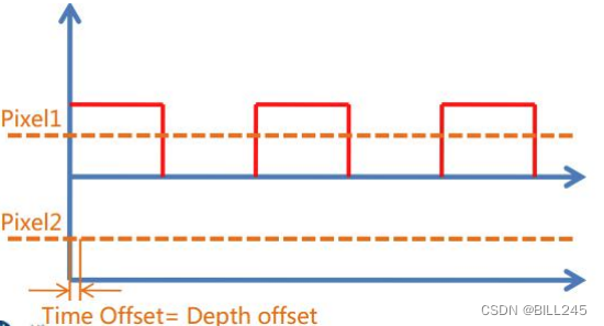
Figure 4.4 Local differences between Pixels
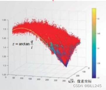
Figure 4.5 Overall Upward Deviation
Cyclic error , because the modulating wave is not a perfect sine wave, or even a square wave. Since all signals can be represented as a combination of harmonics and fundamentals, the error can be expressed as the sum of the fundamental and several harmonics:
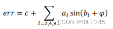
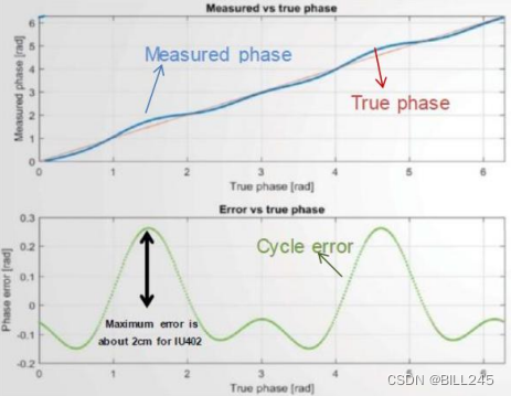
Figure 4.6 Cycle error waveform diagram
Temperature drift , the driver signal of vcsel will be delayed with the increase of temperature, which will lead to the change of measurement distance. Generally speaking, there is a linear relationship between temperature drift and ranging error.
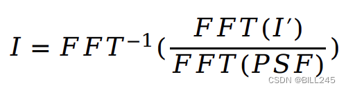
Stray light , when there are obstacles in the environment, the signal will be superimposed, causing the phase to change. Filtering compensation can be done by point spread function (PSF). The point spread function describes the response of an imaging system to a point source of light (object). The general term for PSF is system response, which is the shock response of a focusing optical system. The original image is restored by fast Fourier transform and inverse fast Fourier transform.
4.1.2 Non-systematic errors
Flying pixel (flying point) , for the depth image, the edge of the object in the foreground is connected to the background. Due to the large pixel size, the same pixel may receive the signal reflected by the background and the foreground, and the two signals Fusion occurs, resulting in continuous linear noise at the edge of the object point cloud. This kind of linear noise is generally larger than the point cloud, so it can be filtered by the threshold that changes with the distance. When the distance exceeds the threshold, it is considered as noise, and when the distance is less than the threshold, it is considered as valid information.
Amplitude-related errors , exposure at different heights (or integration time) will cause accuracy problems in ranging (more biased towards accuracy). Can be improved with the auto exposure function.
Interference between multiple devices . When multiple devices are working at the same time, the projected light sources of multiple devices interfere with each device. At present, it can be solved by time division multiplexing or space multiplexing.
Multipath interference is similar to stray light in systematic errors. The difference is that stray light comes from the reflection between the lens and sensor, while multipath interference usually comes from multiple reflections between external target objects. The resulting excess distance can cause greater interference. There is no better solution yet.
Motion blur , both direct and indirect, requires more than 4 exposures. In this process, if the object moves at a certain speed, abnormal detection may occur on the edge, which is called motion blur.
The impact of object material/reflectivity on ranging : mainly reflected in the error of ranging when the received signal strength is too strong or too weak.
Ambient light interference , when the external light is strong, will have a greater impact on ranging. That is, when the external ambient light is strong, it is impossible to judge which part is emitted by the light source.
4.2 Binocular
When the focal length and the baseline are fixed, the error of the depth data Z is only related to the calculation of the parallax d.
Calculate the relationship between the parallax d and the distance Z, and get the matlab simulation diagram as follows:
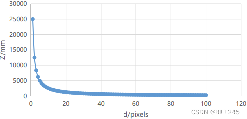
Figure 4.7 The relationship between parallax d and distance Z
As shown in Figure 4.8, the smaller the angle between the two rays and the farther the distance, the greater the error.
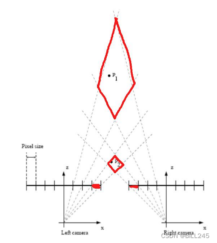
Figure 4.8 Schematic diagram of binocular ranging error
4.3 Structured light
The main sources of system measurement errors are system modeling errors, calibration errors and image processing errors. Due to the limited length of the article, the detailed analysis, derivation and calculation process can be seen:
Xu Li, Zeng Dan, Zhang Zhijiang. Error Analysis of Structured Light Measurement System[J]. Optoelectronic Engineering, 2008(10):26-31+97.
5. Advantages and disadvantages of three 3D technologies
5.1 ToF
5.1.1 Direct measurement method
- Higher requirements on the stability of the optical signal;
- less calculation;
- The measurement distance can be improved by adjusting the pulse period;
- Data jitter is relatively large;
- Fast (~10ns) high performance global exposure is required.
5.1.2 Indirect measurement method
- Relatively loose requirements on the stability of optical signals;
- The amount of calculation is relatively large;
- It is necessary to expand the measurement distance through multiple frequency calculations;
- Data jitter is relatively less.
5.2 Binocular
5.2.1 Advantages
- Due to its passive characteristics, passive binocular has low hardware power consumption;
- The short-distance accuracy is millimeter level, and the error is five thousandths (5mm) within 2m;
- Low hardware requirements and low cost;
- Can be used indoors and outdoors;
- The resolution can reach a higher 2k resolution;
5.2.2 Disadvantages
- Very sensitive to ambient light. Light changes lead to large image deviations, which will lead to matching failure or low accuracy;
- Not suitable for scenes that are monotonous and lack texture. Binocular vision performs image matching based on visual features, and no features will cause matching failure;
- High computational complexity. This method is a purely visual method, which has high requirements on the algorithm and a large amount of calculation;
- Baselines limit the range of measurements. The measurement range is proportional to the baseline (distance between the two cameras), making miniaturization impossible.
5.3 Structured light
5.3.1 Advantages
- Because structured light actively projects coded light, it is ideal for use in poorly lit (or even no-light) scenes that lack texture.
- The structured light projection pattern is generally carefully designed, so it can achieve high measurement accuracy within a certain range.
- The technology is mature, and the depth image can achieve relatively high resolution.
5.3.2 Disadvantages
- The outdoor environment is basically unusable. This is because it is easily affected by strong natural light outdoors, causing the projected coded light to be flooded. Increasing the power of the projection light source can alleviate this problem to a certain extent, but the effect is not satisfactory.
- The measurement distance is relatively close. The farther the object is from the camera, the larger the projected pattern on the object and the lower the accuracy (imagine a flashlight shining far away), and the corresponding lower measurement accuracy. Therefore, the measurement accuracy of the depth camera based on structured light decreases significantly as the distance increases. Therefore, it is often applied more in close-range scenes.
- Susceptible to reflections from smooth surfaces.
6. Post-processing
6.1 ToF
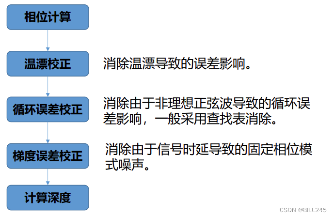
Most systematic errors can be resolved by calibration techniques. Calibration can quantify and model errors, summarize errors into specific values or models, and use them in later calculations and corrections.
6.1.1 Depth data correction
According to the calibrated parameters, it is compensated in the depth calculation. The specific process needs to be consistent with the calibration process.
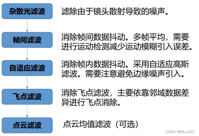
6.1.2 Filtering
Due to reasons such as Flying Pixel or data jitter, the imaging of point cloud images is not perfect. We handle this by filtering.
6.1.3 Automatic Exposure
The goal of the automatic exposure algorithm is to adjust the exposure time in an appropriate way to control the image amplitude to avoid overexposure and underexposure, especially to control the amplitude of the saturated area to keep it within a constant range (corresponding to non-systematic errors Amplitude-dependent errors).
Calculate the recommended exposure value for the next frame by using the ratio (gain) of the reference amplitude and the actual measured amplitude of the current frame. The formula is as follows:
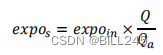
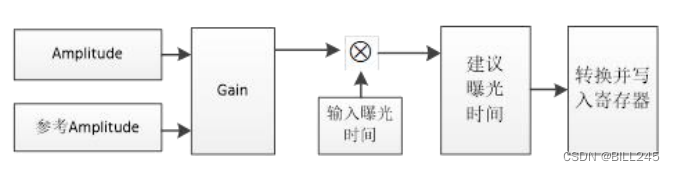
Figure 6.1 Flow chart of automatic exposure
6.1.4 HDRZ
The HDRZ function is realized by setting long and short exposure frames + depth data fusion. According to the functions of different TOF schemes, the methods of long and short exposure can be divided into: front and rear frame long and short exposure and same frame long and short exposure.
In general, fixed exposure is used for long exposures, and automatic exposure is used for short exposures to ensure that there will be no overexposure at close range. Finally, the long-exposure and short-exposure depth data are fused to achieve the goal of HDRZ - both close-range and long-distance targets can be captured.
6.2 Binocular
Left-Right Consistency (LRC) check
The function of LRC check is to realize occlusion detection (Occlusion Detection) and obtain the corresponding occlusion image.
The specific method: according to the two input images, two disparity maps are respectively obtained. For a point p in the left picture, the obtained disparity value is d1, then the corresponding point of p in the right picture should be (p-d1), and the disparity value of (p-d1) is recorded as d2. If |d1-d2|>threshold, p is marked as an occluded point.
Occlusion Filling
A binary occlusion image is obtained, and then a reasonable disparity value is assigned to all black occlusion points. For the left image, occlusion points generally exist where the background area and the foreground area meet. Occlusion occurs precisely because the foreground has a larger offset than the background, thus covering the background.
The specific assignment method is: for an occluded point p, find the first non-occluded point horizontally to the left and right, denoted as pl, pr. The disparity value of point p is assigned to the smaller one of the disparity values of pl and pr. d(p)=min(d(pl),d(pr)) (Occluded pixels have the depth of the background).
Median Filtering
This simple Occlusion Filling method is effective in occlusion area assignment, but it is highly dependent on the rationality and accuracy of the initial parallax. And there will be horizontal streaks similar to the dynamic programming algorithm, so it is often followed by a median filtering step to eliminate the streaks.
For complete and detailed content and pictures, see the following link:
Subsequent processing of stereo matching: left and right detection + occlusion filling + median filtering_lphbtm's column-programmer ITS401
https://its401.com/article/lphbtm/17953347
7. Materials and references
I found some summary comparison charts on the Internet, and put them in this part with reference materials.
7.1 Some references of ToF
The principle and application of Tof
https://blog.csdn.net/qq_42676511/article/details/120723131
Radial error, eccentric error and thin prism error_Hali_Botebie's Blog-CSDN Blog
https://blog.csdn.net/djfjkj52/article/details/121122845
Full Interpretation of ToF Technology_Image Algorithm AI Blog-CSDN Blog_tof Positioning Algorithm
7.2 Dual-purpose partial references
Getting Started with Binocular Stereo Matching [1] (Theory)
Binocular Stereo Matching
https://blog.csdn.net/m0_37604894/article/details/81020846
Vehicle-mounted binocular ADAS (5): The principle, composition, application and challenges of binocular vision technology_bobuddy's blog-CSDN blog_The principle of binocular vision obstacle avoidance
Binocular Stereo Vision (1) Basic Principles and Steps_CodeIsCoding's Blog-CSDN Blog_Binocular Stereo Vision
Machine vision - basic knowledge of binocular vision (parallax depth, calibration, stereo matching)
The principle of binocular vision (summary of thousands of words, including Halcon code)_happylife_mini's Blog-CSDN Blog_Binocular Vision
Explain in simple terms the active binocular stereo vision - Zhihu (zhihu.com)
https://zhuanlan.zhihu.com/p/158051630
7.3 Some reference materials of structured light
Detailed Explanation of the Principle of Structured Light in 3D Vision
The Principle and Application of Structured Light 3D Imaging
https://blog.csdn.net/qq_42722197/article/details/119770044
Error Analysis of Structured Light - CSDN Search
3D-camera structured light principle_wujianming_110117's Blog-CSDN Blog
7.4 Some references for the comparison of three 3D technologies
Analysis of the pros and cons of TOF, RGB binocular, and structured light - Programmer Sought
3D Camera Technology Research (TOF+Binocular+Structured Light)_PKing666666's Blog-CSDN Blog_Structured Light 3d Camera
https://panjinquan.blog.csdn.net/article/details/119649838