Article directory
foreword
Yesterday, through the configuration of the general output mode, the operation of turning on, extinguishing, and running water of the LED light was realized, and the problem of the general output was solved. Today, we will use the most common input module, the button to realize the function of controlling the LED with a button. The key point It is to configure GPIO as input mode and how to detect the input level of GPIO.
module introduction
schematic diagram
The smallest system I use has three independent buttons, which can be operated. First of all, the first step is to look at the schematic diagram to determine the ports and pins we need to use. It can be seen that K_UP uses PA0, K0 uses PE4, KEY1 uses PE3.
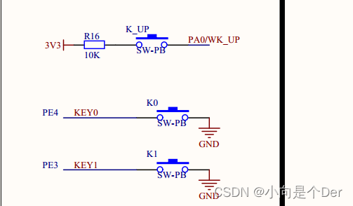
Pay attention to the circuit of these three buttons. Among them, KEY0 and KEY1 have no pull-up resistors, only press the button and directly ground this level mode. We mentioned this when we explained the GPIO mode before. If there is no external pull-up If you want to realize the detection of high and low levels, you need to implement internal programming to achieve pull-up and pull-up. These two buttons need to use internal pull-ups, so that the default PE4 and PE3 ports are high-level by default, which is 1. Only the button is pressed It will be pulled to a low level, that is, 0.
And K_UP, just the opposite, only has a pull-up circuit. When the button is pressed, it is at a high level. When it is not pressed, its default state should be low, that is to say, we need to configure a pull-down for it.
programming ideas
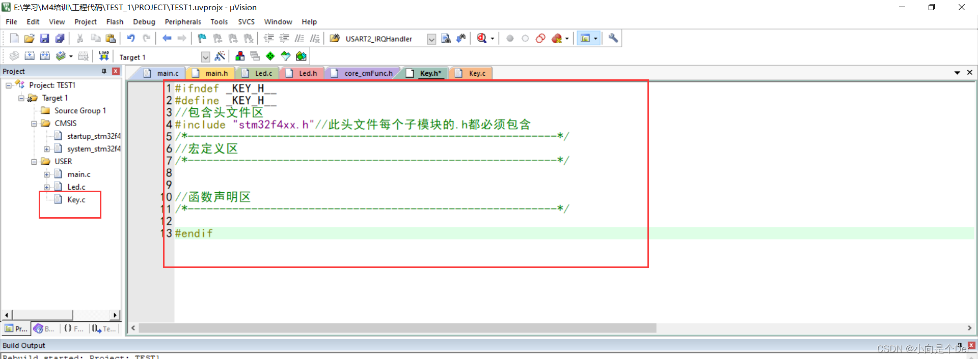
After seeing the detection principle clearly, you need to sort out the programming ideas. According to yesterday’s keystroke skills, you first need to create a new file, name and save key.c in the src folder, key.h in the inc folder, and then save the Key. c is added to the project, and then the header file is defined, and the initialization function is written.
Write initialization code:
Pseudo-code:
① Write comment:
/************************************** ************************************
*Function name: Key_Init
*Function function: the pipe used by the key Pin initialization configuration
*Function parameters: None
*Function return value: None
*Function description:
KEY_UP------PA0------General input mode, the default state is internal pull-down, press the key to be high level
K0----------PE4------General input mode, the default state is internal pull-up, press the button is low level
K1----------PE3-- ----Universal input mode, the default state is internal pull-up, press the button is low level
***************************** *************************************************/
②Initialization Function
void Key_Init(void)
{ ③ Enable the clock corresponding to the port, there are two, one is GPIOA (used yesterday), the other is GPIOE; GPIOA corresponds to the 0th bit, and GPIOE corresponds to the 4th bit. (First check the clock bus connected to it in the data sheet, and then find the corresponding enable in Chapter 6 RCC for configuration)
④Set the mode of the corresponding pin, which is the general input mode, and configure it in two groups. A0: should be configured with two bits of MODER 0 and 1 of GPIOA, and write 00; E3E4 should be configured with bits 9 8 7 6 of MODER of GPIOE Write 0000;
⑤Set pull-up and pull-down, where PA0 is set to pull-down mode, you should write 10 to the 1 0 bits of the PUPDR of GPIOA; PE4, PE3 should write 0101 to the 9 8 7 6 bits of the GPIOE PUPDR register.
}
Well, it can be found that the whole configuration process is a little simpler than yesterday's input configuration, and the registers used for output yesterday are useless for key input.
Let's take a look at the code next.
//注释
void Key_Init(void)
{


	//打开AHB1上GPIOA端口
	RCC->AHB1ENR |= (1<<0);
	//打开GPIOE端口对应的AHB1时钟
	RCC->AHB1ENR |= (1<<4);
	//配置GPIOA0为通用输入模式
	GPIOA ->MODER &=~(3<<0);//清0  GPIOA_MODER寄存器为00通用输入模式
	GPIOA ->PUPDR &=~(3<<0);//清0  GPIOA_PUPDR寄存器为00 浮空
	GPIOA ->PUPDR|=(1<<1);//清0  GPIOA_PUPDR寄存器为10 下拉

	GPIOE->MODER &= ~(0XF<<6);//通用输入
	GPIOE->PUPDR &= ~(0XF<<6);//清零
	GPIOE->PUPDR |=  (0X5<<6);//写入0101配置为上拉模式
}
Detect the level of the IO port
When GPIO is used for output, the output of low level and high level is achieved by writing 0 and 1 to the corresponding bit of the ODR register of the corresponding port. Obviously, if you need to obtain the input status of GPIO, you must only use The way of reading, then, how to read it, referring to the output, there must be a corresponding input data register to obtain the status of the GPIO. When introducing the GPIO register, I mentioned a register called IDR. Its function is Store the high and low levels of GPIO. That is to say, when obtaining the input signal, what needs to be directly operated is the corresponding bit of the IDR register.
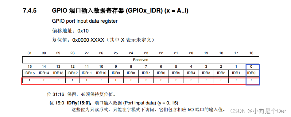
Among them, Key_Up uses the 0th bit of GPIOA->IDR;
K0 uses the fourth bit of GPIOE->IDR; K1 uses the third bit of GPIOE->IDR;
it can be found that this register itself is read-only, So you can't use the '=' assignment statement for it when programming.
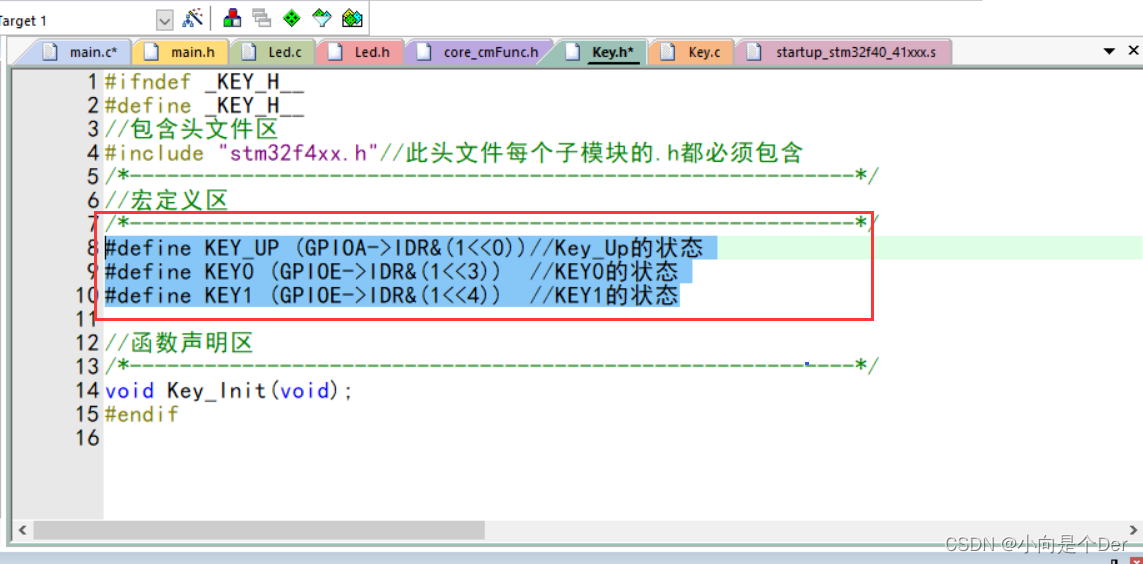
Since it is necessary to obtain the high and low of the corresponding bit of the IDR, consider using the & operation to place 1 on the corresponding bit &, and output 1 when the corresponding bit in the register is 1; output 0 when the corresponding bit in the register is 0; the specific implementation
method as follows:
#define KEY_UP (GPIOA->IDR&(1<<0))//Key_Up的状态
#define KEY0 (GPIOE->IDR&(1<<3))  //KEY0的状态
#define KEY1 (GPIOE->IDR&(1<<4))  //KEY1的状态
The method of macro definition is used, so that the condition can be used to judge whether KEY1, KEY0, and KEY_UP are true to know whether the key is pressed. Since KEY1 and KEY0 are pulled up by default, they are high when they are not pressed. At this time, KEY1 and KEY0 are non-positive. 0, only when the button is pressed is the low level, at this time KEY1 and KEY0 are 0; and KEY_UP is in the pull-down state by default, the default is low level, that is, KEY_UP is 0; only when the button is pressed, GPIO becomes high Level, KEY_UP is non-zero.
Remember to put the macro definition back into the header file of Key.h.
Then call it in the main function (remember to add Key.h into main.h).
1. To detect the state of the button, it must be detected by real-time refresh, so the relevant judgment must be placed in the main loop of While (1), rather than the single-run area above; 2. The detection principles of the three buttons are different
. KEY0 and KEY1 need to detect low level, so the statement to judge is if(!KEY0) and if(!KEY1); while KEY_UP needs to detect high level, so the statement is if(KEY_UP); 3. In
order To see the effect, you need to define three variables, Key_Up, k0, and k1 (use ST-LINK to simulate, use iWatch to view data, of course, you can also use LED lights); 4. Before using a module, you must call the corresponding module in the initialization area
. The module's initialization function.

The code of main.c:
#include "main.h"
u8 Led_Speed=5;
u8 Key_Up=0;
u8 k0=0;
u8 k1=0;
int main(void)
{


/*------------------变量定义区--------------------------*/

/*------------------初始化外设区------------------------*/
	Led_Init();
	Key_Init();
/*------------------单次运行区--------------------------*/

	while(1)//防止程序跑飞
	{


/*------------------主循环区--------------------------*/
			if(KEY_UP)Key_Up++;
			if(!KEY0)k0++;
			if(!KEY1)k1++;
	}
}
After adding the code according to the above steps and location, compile and pass, and then start debugging with iWatch.
DebugDebugging
After the compilation is passed, click the position of 1, and wait for the software to load to enter the following interface. This is the interface for debugging and simulation. In order to see the effect intuitively, now add the Key_Up, k0, and k1 defined above to Watch. The function of this box is It is convenient to view the value of the variable during the simulation process. The adding steps are shown in the figure below:
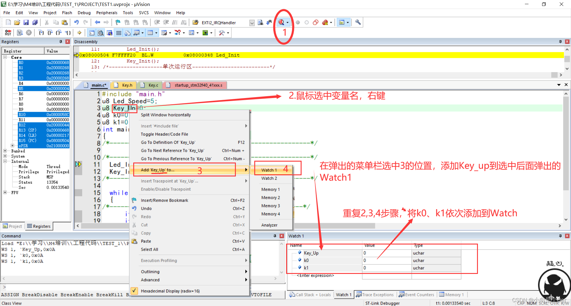
According to the logic of the above code, it should be that pressing the corresponding button will increase the value by 1. According to the imagination, the value should be automatically increased by pressing the button once. 1. Will the actual effect be like this? As shown in the figure below:

It can be found that the actual effect is not that the variable is incremented by one each time the button is pressed, but tens or even hundreds are incremented by each press, which is obviously problematic. So what is the reason for this phenomenon? In fact, it is the main frequency problem mentioned above. According to our code logic, as long as the corresponding IO is detected to be high or low, it will increase automatically. Since the main frequency of STM32F4 reaches 168MHZ , that is to say, it can run 168M machine instructions in 1 second. When we press the button, it starts to increase until we release the button. It is very short for the naked eye and feeling, but this time, The single-chip microcomputer has repeated operations many times, and the phenomenon in the above picture will appear, so how to solve this problem. This requires the use of the button scan function.
key scan function
The above problem occurs because the condition of if() has been true for a period of time after the button is pressed, causing the variable to keep increasing, so how to solve the problem of self-incrementing? And the flag bit is locked to solve this problem, first look at the code:
/*******************************************
*函数名    :Key_Scanf
*函数功能  :按键扫描
*函数参数  :void
*函数返回值:key_value键值
*函数描述  :
告诉主函数按下的是哪个按键。
判断案件是否按下,并返回对应键值。
*********************************************/
u8 Key_Scanf(void)
{


		u8 key_value=0;//初始键值
		static u8 Key_Flag=0;
		if(KEY_UP && Key_Flag == 0)//判断按键是否按下
		{


				key_value=1;//对按下的按键进行赋值
				Key_Flag=1;
		}
		if(!KEY_UP)//判断按键是否松开
		{


			Key_Flag =0;
		}
		return key_value;//返回键值
}
By adding a Key_Flag to realize the judgment and locking of the key, after detecting that the key is pressed, the flag position is set to 1, so that even if the KEY_UP is always true during the entire pressing period, due to the limitation of the subsequent flag, it cannot be affected. The Key_Flag is not released until it is detected that the key is released, which also ensures that the next time the key is pressed will not be affected. Call in the main function, and then repeat the above Debug simulation.

this time, it can be clearly seen that it is incremented by 1 each time, but there is still a problem, that is, sometimes it is obviously only pressed once, and two or three numbers are added consecutively, which is due to the physical vibration of the button Caused.
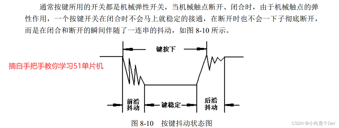
In order to solve this problem, there are also two ways, one is to eliminate the hardware by connecting capacitors in parallel at both ends of the button, but in actual use, it is rare to do this, after all, it can save money; the main reason is that the other way is Use the code to delay the solution, and no material cost is required.
delay function
Here is an introduction to the simple delay function of STM32. As mentioned earlier, STM32F407 can run 168M machine instructions in one second, 168,000 in 1ms, and 168 machine instructions in 1us. It should be noted that a machine instruction is not equal to a C statement. According to rumors, a C statement can be approximated It is equivalent to 4 machine instructions, but that is a rumor after all, not necessarily accurate.
According to the above logic, we let the STM32F407 MCU run 168 machine instructions to get a function of approximately 1us, but where can we find this machine instruction? In fact, there is a machine instruction in the project, which is __nop, so we have the following The us delay and millisecond delay function:
/*******************************************
*函数名    :Delay_us
*函数功能  :机器指令微妙延时函数
*函数参数  :微秒数u32 us
*函数返回值:无
*函数描述  :
利用机器指令nop实现延时
1s---------168M条机器指令
1ms---------168 000 条机器指令
1us---------168条机器指令
*********************************************/
void Delay_us(u32 utime)
{


	while(utime--)
	{


		//1us的延时时长
		__nop();__nop();__nop();__nop();__nop();__nop();__nop();__nop();__nop();__nop();
		__nop();__nop();__nop();__nop();__nop();__nop();__nop();__nop();__nop();__nop();
		__nop();__nop();__nop();__nop();__nop();__nop();__nop();__nop();__nop();__nop();
		__nop();__nop();__nop();__nop();__nop();__nop();__nop();__nop();__nop();__nop();
		__nop();__nop();__nop();__nop();__nop();__nop();__nop();__nop();__nop();__nop();
		__nop();__nop();__nop();__nop();__nop();__nop();__nop();__nop();__nop();__nop();
		__nop();__nop();__nop();__nop();__nop();__nop();__nop();__nop();__nop();__nop();
		__nop();__nop();__nop();__nop();__nop();__nop();__nop();__nop();__nop();__nop();
		__nop();__nop();__nop();__nop();__nop();__nop();__nop();__nop();__nop();__nop();
		__nop();__nop();__nop();__nop();__nop();__nop();__nop();__nop();__nop();__nop();
		__nop();__nop();__nop();__nop();__nop();__nop();__nop();__nop();__nop();__nop();
		__nop();__nop();__nop();__nop();__nop();__nop();__nop();__nop();__nop();__nop();
		__nop();__nop();__nop();__nop();__nop();__nop();__nop();__nop();__nop();__nop();
		__nop();__nop();__nop();__nop();__nop();__nop();__nop();__nop();__nop();__nop();
		__nop();__nop();__nop();__nop();__nop();__nop();__nop();__nop();__nop();__nop();
		__nop();__nop();__nop();__nop();__nop();__nop();__nop();__nop();__nop();__nop();
		__nop();__nop();__nop();__nop();__nop();__nop();__nop();__nop();
	}
}


/*******************************
函数名:Delay_ms
函数功能:机器指令实现ms延时
函数形参:u32 mtime
函数返回值:void
备注:
1s  168M
1MS 168k
1us 168
********************************/
void Delay_ms(u32 mtime)
{


	while(mtime--)
	{


		//1ms的延时
		Delay_us(1000);
	}
}
Similarly, in order to facilitate subsequent management, it is also necessary to create a new Delay.c and Delay.h, then add .c to the project, and include .h into the header file of main.h.
Then add delay debounce in the Key_Scanf() function, and add the remaining two keys. The final Key_Scanf function is as follows:
/*******************************************
*函数名    :Key_Scanf
*函数功能  :按键扫描
*函数参数  :void
*函数返回值:key_value键值
*函数描述  :
告诉主函数按下的是哪个按键。
判断案件是否按下,并返回对应键值。
*********************************************/
u8 Key_Scanf(void)
{


		u8 key_value=0;//初始键值
		static u8 Key_Flag=0;
		if(KEY_UP && Key_Flag == 0)//判断按键KEY_UP是否按下
		{


			Delay_ms(10);//消抖
			if(KEY_UP)
			{


				key_value=1;//对按下的按键进行赋值
				Key_Flag=1;
			}
		}

		else if(!KEY0 && Key_Flag == 0)//判断按键KEY0是否按下
		{


			Delay_ms(10);//消抖
			if(!KEY0)
			{


				key_value=2;
				Key_Flag=1;
			}
		}
		else if(!KEY1 && Key_Flag == 0)//判断按键KEY1是否按下
		{


			Delay_ms(10);//消抖
			if(!KEY1)
			{


				key_value=3;
				Key_Flag=1;
			}
		}

		if(!KEY_UP&& KEY0 && KEY1)//判断按键是否松开
		{


			Key_Flag =0;
		}
		return key_value;//返回键值
}
function realization
Through the above process, the input detection of the key is basically done. Next, a small requirement is realized. Press the key KEY_UP, the small light 1 is on, press the KEY0, the small light 2 is on, and press the KEY1, the two small lights are off together.
The specific implementation of main.c is as follows:
int main(void)
{


/*------------------变量定义区--------------------------*/
 u8 K_Value=0;
/*------------------初始化外设区------------------------*/
	Led_Init();
	Key_Init();
/*------------------单次运行区--------------------------*/

	while(1)//防止程序跑飞
	{


/*------------------主循环区--------------------------*/
		K_Value=Key_Scanf();
		switch(K_Value)
		{


			case 1:Key_Up++;LED_1_ON;break;
			case 2:k0++;LED_2(1);break;
			case 3:k1++;LED_1_OFF;LED_2(0);break;
			default : break;
		}

	}
}
final effect:

Summarize
This article mainly records the function of configuring GPIO as input mode and detecting key input. If you have any questions, please raise them. In addition, if there are any deficiencies in the article, you are also welcome to criticize and correct.