external interruption
foreword
In the previous article, the interrupt management and specific configuration of STM32 were introduced. This article uses the previous configuration process to realize the external interrupt function.
Introduction to EXTI
What is EXTI
It’s still an old routine. First, let’s figure out what EXTI is. EXTI is the external interrupt of STM32. Since it is called an external interrupt, then its interrupt must come from outside the kernel. The description in the figure below says that it can be used to detect external events, but it is not. It's too complete. It will be clear after reading the block diagram. In fact, external interrupts can also be triggered by software.
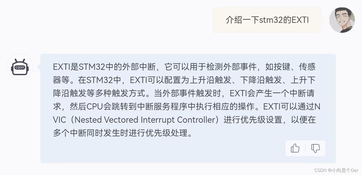
The description in the above figure also mentioned that EXTI can be configured as rising edge trigger, falling edge trigger, rising and falling edge trigger and other trigger modes. These are the interrupt signals mentioned in the previous article, that is, each branch of the entire external interrupt switch.
Main features of EXTI
quantity
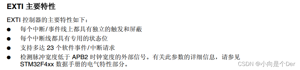
The external interrupt/event controller contains up to 23 edge detectors for generating event/interrupt requests. The
main function is to generate interrupt requests through edge detection. It has 23 EXTI interrupt lines
, of which 0~15 are interrupt lines It is used to handle the edge detection corresponding to the GPIO port, and
16~22 is used to handle other on-chip peripherals, such as RTC and the like.
Corresponding to the naming of the interrupt source
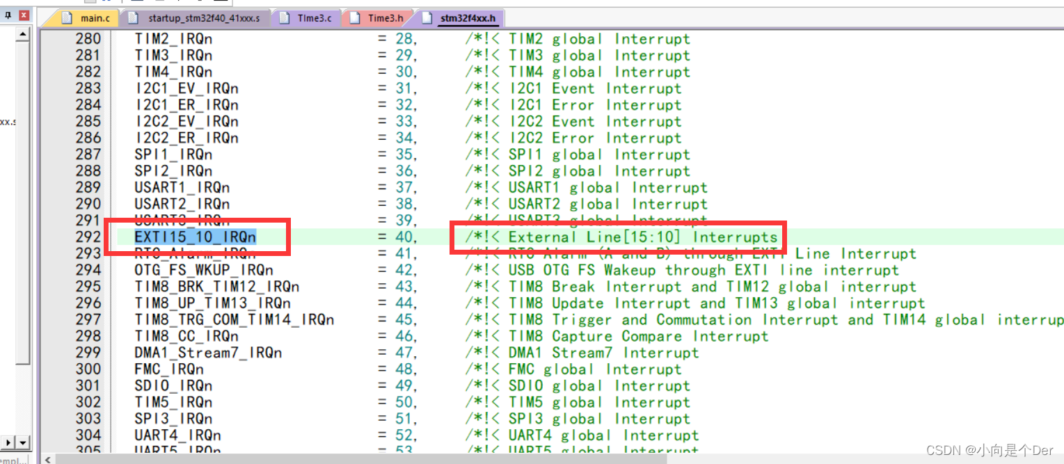
As we mentioned in the previous article, the corresponding interrupt will have a unified interrupt source name, so what is the naming of the external interrupt source here? You can see it in stm32f4xx.h, EXTI0, EXTI1 EXTI2, EXTI3 , EXTI4 is an independent interrupt source, while EXTI5_9 uses the same interrupt source, and EXTI15_10 uses the same interrupt source; as for the other 16-22, we will talk about it later.
One thing needs to be clarified here, that is how the GPIO port and the EXTI interrupt are connected,
for example:
external interrupt line: EXTI1 corresponding GPIO pin: PA1 PB1 PC1 PD1 PE1 PF1 PG1 PH1 PI1
That is to say: every One interrupt line corresponds to pins 0–15 of the GPIO port, and the interrupt line corresponds to GPIO0~15 pins.
PA0 corresponds to EXTI0; PC9 corresponds to EXTI9; PD9 corresponds to EXTI9.
Block Diagram of EXTI
After understanding some basic information of external interrupts, according to the previous routine, we must understand how to configure external interrupts, and the first task in the middle is to understand its block diagram, and figure out its general workflow and programming process.
The official block diagram is shown below, but since we mainly use external interrupts, the time control part in the red box can be ignored directly.
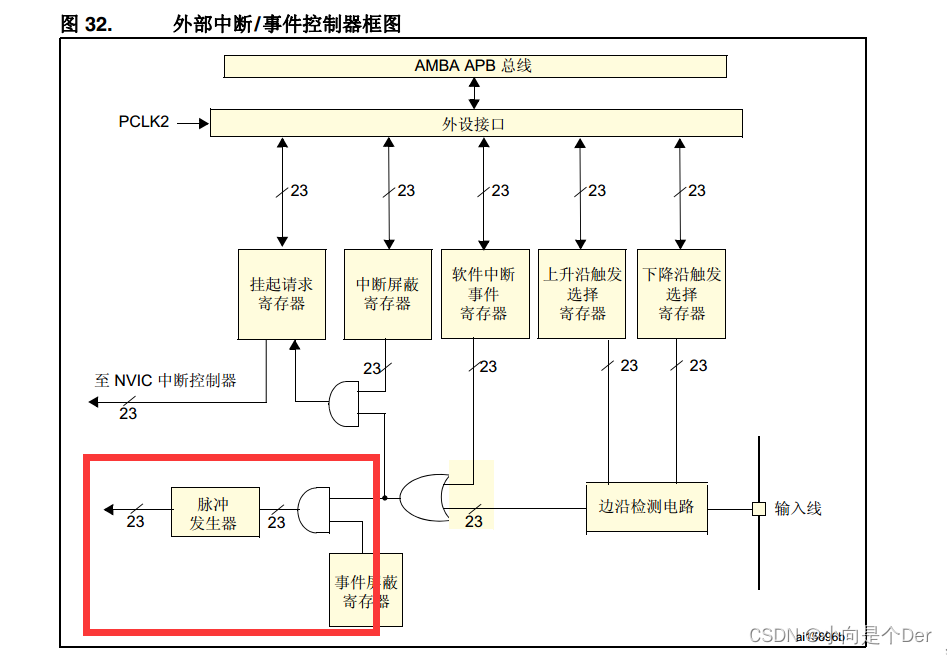
After simplification, it is shown in the figure below:
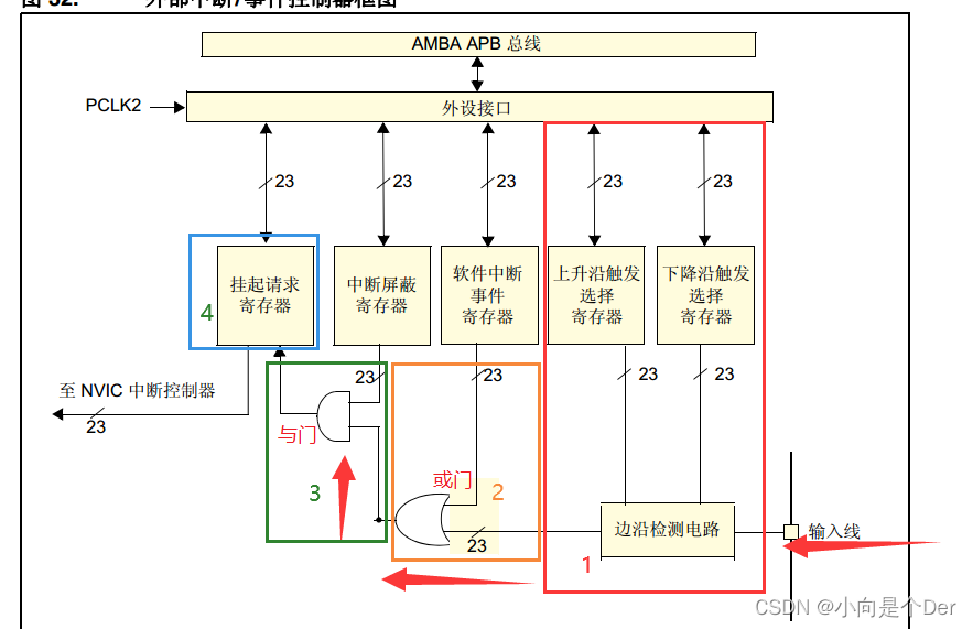
sort out the process according to the input direction.
1. The input signal first reaches the edge detection circuit in the red box No. 1 through the input line. This circuit is controlled by the two registers above, one is the rising edge trigger selection register , and the other is the falling edge trigger selection register . The programmer programs to select the rising edge , falling edge or both modes of rising and falling edges at the same time
; 2. After passing the edge detection circuit, it comes to the position of No. 2 orange frame, where there is an OR gate, the OR gate The logic is that if any of the two inputs is established, you can go backwards. That is to say, if you did not configure edge detection in the previous step, configuring a software interrupt event directly here can also trigger an external interrupt. This is just mentioned, external interrupt It not only has the function of detecting the edge, it can also use software to trigger an interrupt. This software interrupt register is also controlled by the programmer. As long as the corresponding value is written to the register, it will trigger an interrupt; 3. After 2
boxes After the OR gate, there is an AND gate. The logic of this AND gate is that when both inputs are established at the same time, there will be a corresponding output. Here, one input is from the previous edge detection or software trigger, and the other input is from a Interrupt mask registerThat is to say, when the programmer is operating, this register must be set to 1, so that the entire circuit can continue to execute, and its effect is equivalent to the enable bit mentioned above, which must be enabled Can perform the following functions.
4. After the previous operation and configuration, the signal came to something called the suspend request register, and then directly entered the interrupt controller. It can be seen that this register must be used to monitor the state of the signal, which can be passed It is used to determine whether an interrupt has occurred.
The /23 in the figure represents 23 external interrupt lines.
configuration process
Through the above block diagram analysis, we can roughly analyze the configuration process of the external interrupt:
① Determine what value needs to be written to the interrupt line corresponding to the IO port
② Configure the edge trigger of the corresponding EXTI line
③ Enable the interrupt enable of the EXTI line
④ Configure the interrupt source enable of the EXTI line
⑤ Write interrupt service function
Register introduction
After analyzing the configuration process, you need to study the specific register description. Note that the EXTI register is in Chapter 10, Section 3 of the Chinese Reference Manual.
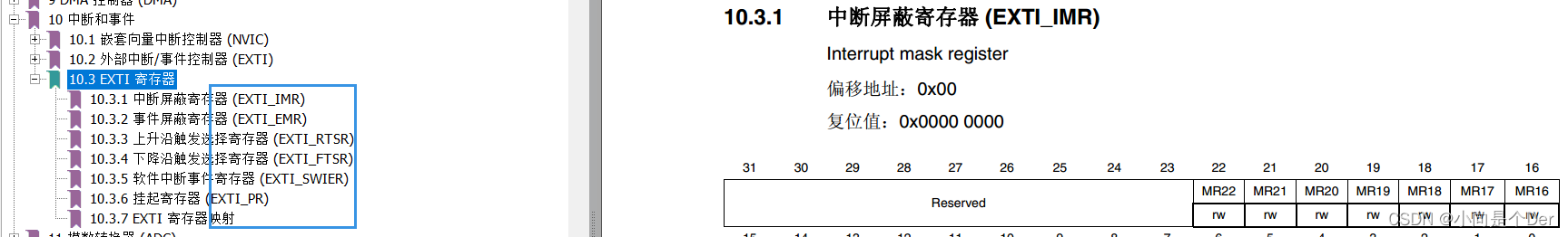
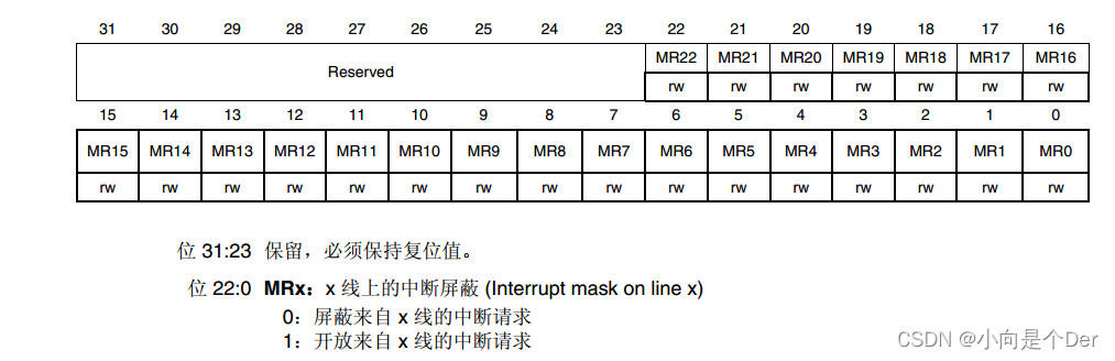
1. Interrupt mask register EXTI_IMR
writing method: EXTI-> IMR
function: each bit x indicates that the corresponding EXTIx
opens the corresponding interrupt line interrupt request (interrupt enable). Write 1 to the corresponding bit to open the corresponding interrupt line enable.
2. As the name implies, the event mask register (EXTI_EMR)
is just the opposite of the function of the previous register. It can be used to mask the request of the related interrupt line. Generally, it is not used, and there is no need to mask it.
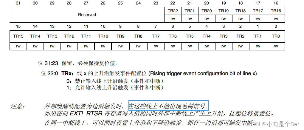
3. Rising edge trigger selection register (EXTI_RTSR)
writing method: EXTI-> RTSR
function: Each bit x indicates that the corresponding EXTIx
opens the corresponding interrupt line rising edge triggering, and the corresponding position 1 can enable the rising edge triggering.
4. Falling edge trigger selection register (EXTI_FTSR)
writing: EXTI-"FTSR
function: each bit x indicates that the corresponding EXTIx
opens the corresponding interrupt line falling edge triggering, and the corresponding position 1 can enable the falling edge triggering.
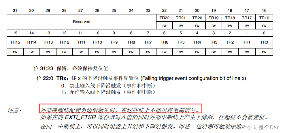
Note that glitch signals cannot be used during edge detection, that is to say, the input waveform must be smooth without jitter.
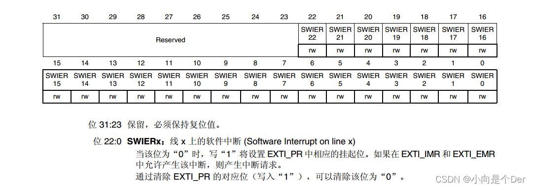
5. Software interrupt event register (EXTI_SWIER)
writing method: EXTI->SWIER
function: each bit x indicates the corresponding EXTIx
to make the corresponding EXTI line generate an interrupt request, and the effect of a software triggering an external interrupt can be realized by setting the software to one.
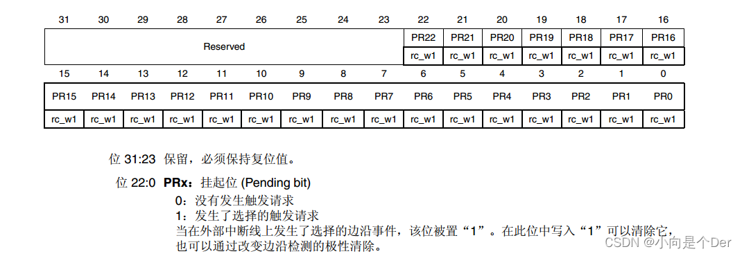
6. The writing method of the pending register (EXTI_PR)
: EXTI->PR
function: each bit x indicates that the interrupt line corresponding to the corresponding EXTIx
generates an interrupt, then set 1
and write 1 to clear the status bit, the interrupt flag bit, If an interrupt occurs on the corresponding line, the corresponding register will be set to one, and this is used as a flag when judging the interrupt.
The above parts can be found in the block diagram. In fact, a register is required to use the external interrupt. As mentioned earlier, an EXTI line will correspond to multiple pins, so how does the system know which pin is mapped to it? As for the corresponding EXTI line,
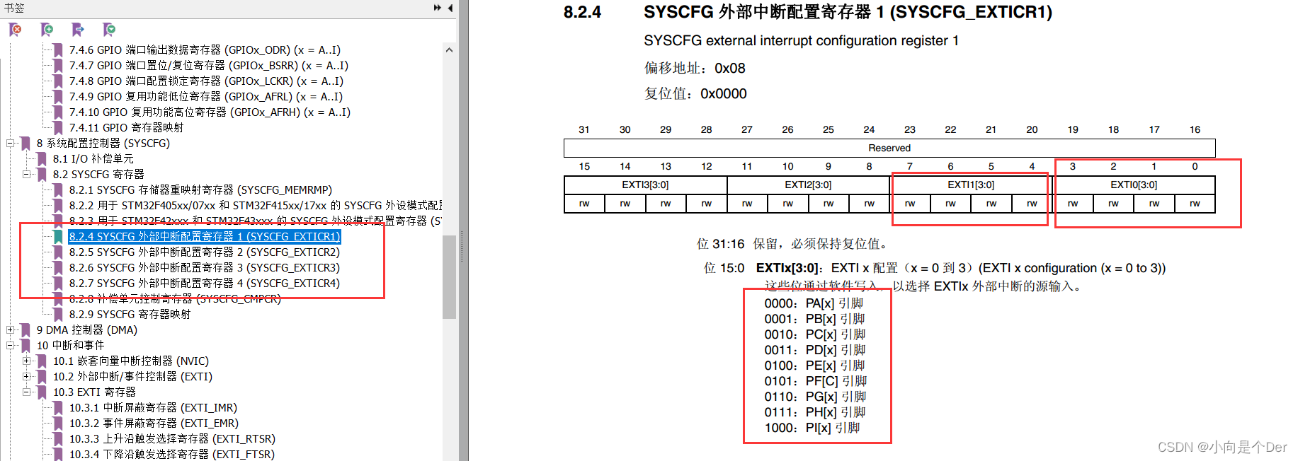
this requires the use of the external interrupt configuration register : SYSCFG->EXTICR, in Chapter 8 of the manual, as shown in the figure below, each of the four corresponds to an EXTI line, write to these four bits The corresponding value can be selected to the corresponding pin.
Take a chestnut:
We need to configure the external interrupt of PA0. First, the external short-term line corresponding to PA0 is EXTI0, and the corresponding external interrupt configuration register is 0-3 bits of SYSCFG_EXTICR1, and the PA port should be written as 0000.
Specifically written:
SYSCFG->EXTICR[0] &=~(0xf<<0);
注意SYSCFG_EXTICR1的写法是SYSCFG->EXTICR[0];
SYSCFG_EXTICR2的写法是SYSCFG->EXTICR[1],依次类推。
To give another example
, the external interrupt of PE4 needs to be configured. First, the corresponding external interrupt line is EXTI4, and its corresponding external interrupt configuration register is 0-3 bits of SYSCFG_EXTICR2, PE port, so it should be written to 0100; so its
specific It is written as follows:
SYSCFG->EXTICR[1] &= ~(0xf<<0);   //先清零
		SYSCFG->EXTICR[1] |=  (0X4<<0);   //GPIOE4映射到EXTI4
programming ideas
Well, the configuration process of the external interrupt has been roughly cleared so far. Note, don’t forget that the interrupt is used, so it is necessary to have the configuration related to the NVIC controller yesterday. Here is a summary of a specific pseudocode:
新建exti文件
配置思路:
EXTI的初始化函数
{


  //打开时钟 PA时钟  SYSCFG时钟
  //IO口配置    属于特殊的映射  不需要配置
  //EXIT控制器
   SYSSFG_EXTICR寄存器 IO映射
   上下边沿检测
   中断使能
  //NVIC控制器
   优先级配置
   中断源使能
}

在nvic.c写中断服务函数 中断服务函数根据使用EXTI线
Void 中断服务函数(void)
{


   判断触发
   {


      //清除标志位
      //紧急事件
   }
}
programming
According to the above requirements, create a new corresponding file, and then add the code. I won’t post all the code here. If you need it, please send a private message. The effect achieved by the author is three buttons. Pressing the corresponding variable will automatically increase
Exti.c
#include "Exti.h"

u16 K_UP_cnt,K0_cnt,K1_cnt;
/*******************************************
*函数名    :Exti0_Init
*函数功能  :外部中断0初始化函数
*函数参数  :无
*函数返回值:无
*函数描述  :
PA0——对应EXTI0中断线,上升沿触发
PE3——对应EXTI3中断线,下降沿触发
PE4——对应EXTI4中断线,下降沿触发
*********************************************/
void Exti0_Init(void)
{


		u32 pri;//存储优先级合成函数返回的优先级
		RCC->AHB1ENR  |= (1<<0);		//打开AHB1上GPIOA端口
		RCC->APB2ENR  |= (1<<14);   //打开SYSCFG的时钟使能,
/*---------------------------------------------------------------------------------*/
		//IO配置GPIOA,通用输入,可不配置

/*-----------------------------------------------------------------------------------*/
		SYSCFG->EXTICR[0] &= ~(0xf<<0);  //配置GPIOA0与EXTI0映射连接——第八章系统配置控制器 (SYSCFG)

		SYSCFG->EXTICR[0] &= ~(0XF<<12); //先清零
		SYSCFG->EXTICR[0] |=  (0X4<<12);  //(GPIOE3映射到EXTI3)

		SYSCFG->EXTICR[1] &= ~(0xf<<0);   //先清零
		SYSCFG->EXTICR[1] |=  (0X4<<0);   //GPIOE4映射到EXTI4

		EXTI->RTSR  |= (1<<0);//配置EXTI0为上升沿有效——第十章 10.3 EXTI 寄存器
		EXTI->FTSR  |= (1<<3);//配置EXTI3为下升沿有效
		EXTI->FTSR  |= (1<<4);//配置EXTI4为下升沿有效

		EXTI->IMR   |= (1<<0);//使能EXTI0的中断
		EXTI->IMR   |= (1<<3);//使能EXTI3的中断
		EXTI->IMR   |= (1<<4);//使能EXTI4的中断
/*------------------------------------------------------------------------------------*/
		//NVIC控制器配置EXTI0
		pri=NVIC_EncodePriority(7-2,0,2);
		NVIC_SetPriority(EXTI0_IRQn,pri);
		NVIC_EnableIRQ(EXTI0_IRQn);

				//NVIC控制器配置EXTI3
		pri=NVIC_EncodePriority(7-2,1,0);
		NVIC_SetPriority(EXTI3_IRQn,pri);
		NVIC_EnableIRQ(EXTI3_IRQn);
				//NVIC控制器配置EXTI4
		pri=NVIC_EncodePriority(7-2,1,1);
		NVIC_SetPriority(EXTI4_IRQn,pri);
		NVIC_EnableIRQ(EXTI4_IRQn);

}


/*******************************
函数名:EXTI0_IRQHandler
函数功能:EXTI0的中断服务函数函数
函数形参:无
函数返回值:void
备注:
********************************/
void EXTI0_IRQHandler(void)
{


	if(EXTI->PR & (1<<0))//EXTI0产生了上升沿中断
	{


		EXTI->PR |= (1<<0);
		K_UP_cnt++;
	}
}


/*******************************
函数名:EXTI3_IRQHandler
函数功能:EXTI3的中断服务函数函数
函数形参:无
函数返回值:void
备注:
********************************/
void EXTI3_IRQHandler(void)
{


	if(EXTI->PR & (1<<3))//EXTI3产生了下升沿中断
	{


		EXTI->PR |= (1<<3);
		K0_cnt++;
	}
}

/*******************************
函数名:EXTI4_IRQHandler
函数功能:EXTI4的中断服务函数函数
函数形参:无
函数返回值:void
备注:
********************************/
void EXTI4_IRQHandler(void)
{


	if(EXTI->PR & (1<<4))//EXTI3产生了下升沿中断
	{


		EXTI->PR |= (1<<4);
		K1_cnt++;
	}
}
Ex.h
#ifndef _EXTI_H__
#define _EXTI_H__
#include "stm32f4xx.h"
void Exti0_Init(void);
#endif
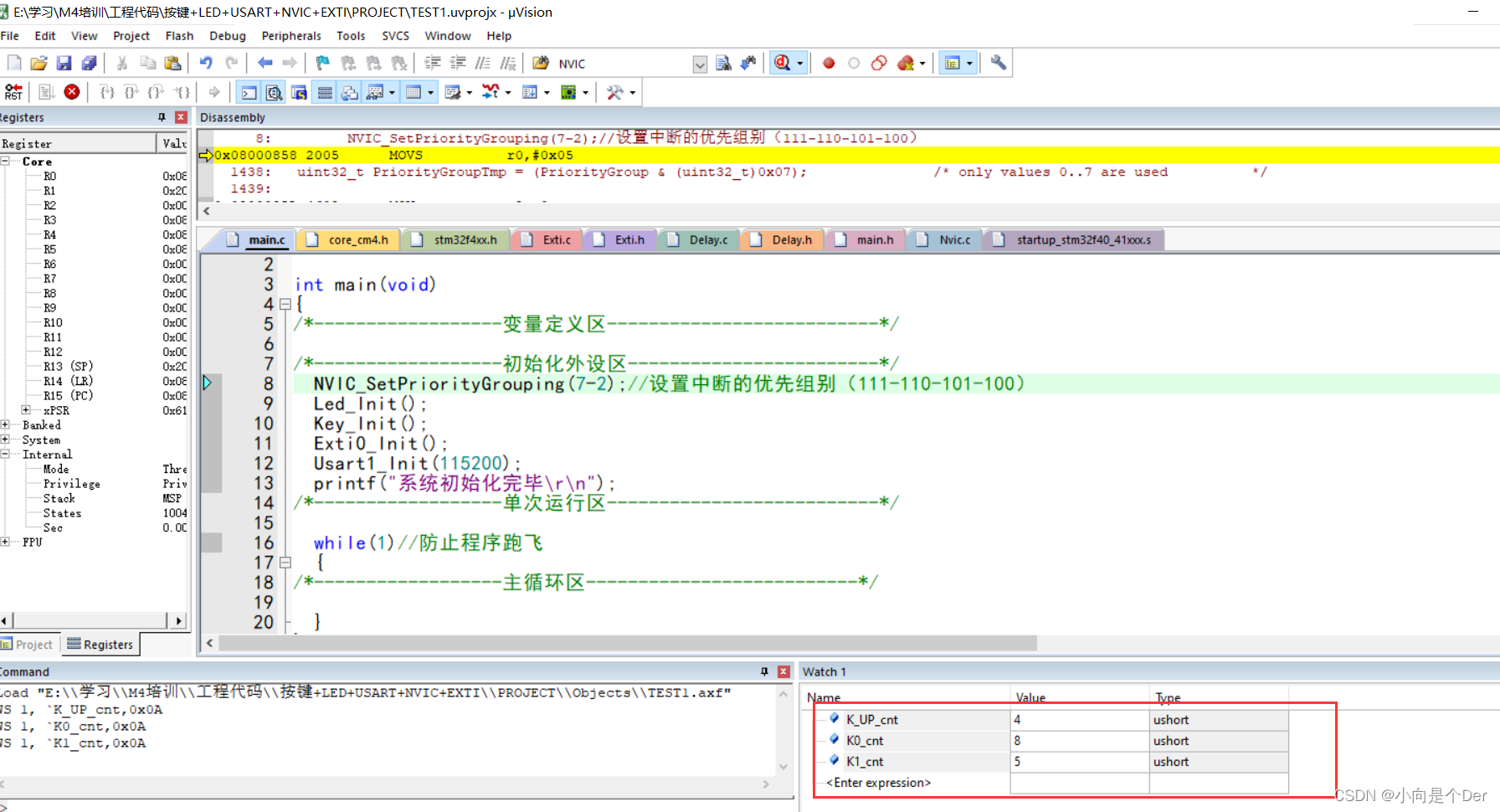
Effect
Press the corresponding button, and the value of WATCH in the lower right corner will increase accordingly.