1661[Bi She Course Design] Design of Intelligent Fingerprint Attendance System Based on 51 MCU-Schematic Diagram-PCB-Program-Report
Summary
With the continuous development of science and technology, the status of the electronic industry is getting more and more important. Now electronic products can be seen in almost all fields of society. The development of these technologies effectively drives the development of social productivity and the improvement of informatization, and electronic products are becoming more and more intelligent.
As the beginning of biometric technology research and development, fingerprint recognition technology has been widely used. It can be seen everywhere in our daily life. The most common one is the fingerprint unlocking of mobile phones today. This kind of fingerprint recognition technology can identify unique fingerprint characteristics, so as to determine the identity of the owner. Compared with the traditional RFID card swiping method, this kind of fingerprint recognition system can avoid the feature of punching cards.
Key words: 51 single-chip microcomputer; fingerprint identification; liquid crystal display
2 System hardware solution selection
This chapter mainly introduces the selection and comparison of the devices used in the system, and makes a comprehensive comparison to select a group of solutions that are most suitable for this design.
2.1 Selection of hardware solutions
Before the construction of the hardware circuit, the design scheme must be clarified, and the most suitable hardware for this design can be selected through comparison between various modules, so as to maximize the effectiveness of the device.
2.1.1 Selection of main control chip
Option One:
STC89C52 microcontroller is used as the main control chip. STC89C52 is a low-power, high-performance eight-bit CMOS microprocessor produced by Hongjing Technology Co., Ltd., with 8k in-circuit programming Flash memory on-chip. The core of the STC89C52 single-chip microcomputer adopts the MCS-51 core, and the instructions are fully compatible with the MCS-51. However, the more upgraded the single-chip microcomputer, the chip has many functions that the traditional 51 single-chip microcomputer does not have. For example, the chip also has 4K EEPROM storage. When it is necessary to use the power-down storage data, the internal storage of the single-chip microcomputer can be directly used, and no external storage chip is required for storage. STC89C52 MCU is a very good choice for its simple development, online programming download, and low cost.
Option II:
MSP430 microcontroller is used as the main control chip. The MSP430 single-chip microcomputer is called a mixed-signal processor. It can integrate multiple analog circuits, digital circuit modules and microprocessors with different functions on one chip. A 16-bit ultra-low power consumption, with a reduced instruction set (RISC) mixed signal processor (Mixed Signal Processor). This series of microcontrollers are mostly used in portable instruments that require battery power. However, it is relatively difficult to develop and expensive. Therefore, it should not be used in some simple designs.
third solution:
The PIC16F877A microcontroller is used as the main control chip. PIC16F877A is a new product produced and developed by Microchip Company. It belongs to the 8-bit single-chip microcomputer of the PICmicro system. It has the function of Flash program memory and can repeatedly erase and write programs. However, the development cost is high and the difficulty is relatively large.
Based on the above description, considering the reasonable utilization of resources, cost and the difficulty of development, it is finally decided to use the STC89C52 single-chip microcomputer of Hongjing Technology as the main control chip.
2.1.2 Selection of fingerprint module
The AS608 fingerprint recognition module is adopted. The AS608 fingerprint recognition module contains high-speed DSP processing to realize the collection and recognition of fingerprints. The common serial port communication protocol is used between the single-chip microcomputer and the module, which makes the design simple. Operations such as fingerprint collection, recognition, deletion, and addition can be controlled through the serial port.
/*************************************************************
                         指纹考勤系统

补充说明:
***************************************************************/
#include<reg52.h>            //头文件
#include<LCD12864.h>
#include<AT24C02.h>
#include<KEY.h>
#include<AS608.h>
#include<DS1302.h>

#define uchar unsigned char    //宏定义
#define uint unsigned int
#define ulong unsigned long

#define AT24Cxx_MAX 255//AT24Cxx最大地址
#define MAX 34         //指纹最大数量

#define ID_MAX 3 //输入ID最大位数

/*****************变量定义*********************/
uchar mode=0;    //0正常打卡,1管理界面,2注册模式,3删除模式
                 //4查询模式,5修改密码,6校准时钟,7工作时间

uchar mode_num=0;

uint ID=0;          //存储输入编号ID
uchar n=0;         //输入的位数
bit zhiwen_f=0;     //1=标记进入指纹采集
uchar chaxun_num=0;//查询编号

uchar a;         //存储按键值
uchar num;         //记录输入的密码位数
bit   in_f;         //输入密码的标志
bit   reset_f;     //重设密码的标志
bit   input_f;     //六位密码按完的标志
uchar reset_num; //标记修改密码阶段,=1输入旧密码,=2输入新密码,=3再次输入新密码

ulong low_mima=0;//系统密码
ulong in_mima=0; //暂存输入的密码
ulong new_mima=0;//暂存输入新密码

uchar set_f=0;     //设置选择变量
uchar temp[5]="    \0";//显示暂存变量
uint fen[5]={0}; //存储工作时间
uchar date=0;    //0今天,1昨天,2前天
uchar day[2];     //记录查询的日期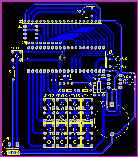


1660[Complete Course Design] Smartphone Charger Design Based on 51 MCU and MAX1898
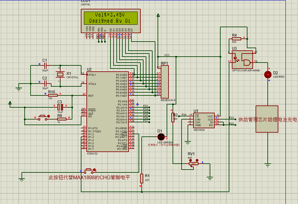
This design takes the single-chip microcomputer 89C51 as the core, and uses the intelligent management chip MAX1898 of the lithium battery to intelligently control the charging process, and combines the 6N137 optocoupler chip to protect the battery by fully charging and power-off. And it adopts ADC0832 analog-to-digital conversion chip combined with LCD1602 liquid crystal display to display the charging voltage status, and adds SIM300 module to send full information to the user when it is fully charged. This post contains all the information of the design, including Proteus simulation of the effect of the main control module, Altium designs the general schematic diagram, and designs the PCB diagram from the schematic diagram.
此体系的硬件设计包含以单片机89C51和充电芯片MAX1898为主要的控制的模块,SIM300模块是系统中发送短信息的模块。其它硬件部分包括电源转换部分、由ADC0832为核心的电压采集模块、6N137光耦控制模块、LCD1602显示模块等。软件设计包括主程序、读取电压子程序、显示数据子程序、SIM300信息收发信息程序。


1661[毕设课设]基于51单片机的智能指纹考勤系统设计-原理图-PCB-程序-报告
1660[毕设课设]基于51单片机和MAX1898的智能手机充电器设计
文章转自电设屋,完整资料百度网盘下载地址:百度网盘 www.aiesst.cn/share.html
单片机学习建议
1.学习前提
单片机是需要与程序打交道的,这个需要您先掌握很基础的C语言知识,即便我们讲解程序的执行过程尽量详细,但对于没有任何C语言知识基础的同学来说这将是举步维艰的。
所以您必须掌握以下最基本的知识
1.数据类型
2.十六进制,十进制,二进制之间的转换
3.程序的运行顺序
4.if,else,while,for,switch等语句
没有C语言基础的同学请提前学习C语言
2.硬件
如果您对模电数电知识没有相关概念,以及对电子元器件尚不知晓,这些都不是学习单片机的困难,我们都会在教程里简单介绍硬件基础,您也可以参考学习宋老师的《手把手教你学51单片机》的前三章,这些只要您对中学物理电路和电路基础知识有一定的了解都可以看得懂。我们也鼓励大家学会在网上查找相关资料加深对电路知识和单片机的认知。
3.软件
编程环境的软件采用蓝色图标的keil4,电路原理图我们在Altium Designer软件下截图解析,keil4软件的安装和环境搭建不是本教程的讲解内容,请大家自行寻找详细的相关配置教程。
4.教程安排须知
因为单片机内部硬件知识对初学者来说比较抽象,讲解较费笔墨,所以碰到新的概念时我们无需钻牛角尖深究,只需记住这个东西有这么一个规律即可。我们重点在于讲解如何编程。
后期所用到的模块实物与单片机连接时,我们均用原理图上的连接表示。
5.进阶
虽然入门单片机首先从51单片机开始,但现在已经红遍大江南北的首选控制器为stm32,在实际中运用单片机做项目可能也是采用stm32居多,但51的编程思想在stm32上是不可磨灭的。
stm32已经成为主流的单片机,因其性能和外设资源还有价格综合起来的性价比都已远超51单片机,产品的项目设计和电子竞赛也大部分采用stm32单片机做控制,但是学习和运用stm32又需要很多基础,其中80%基础都来源于51,所以我们一步步走,学完51单片机再进阶stm32,这个过程打下的基础将对我们后期学习新的高级控制器有着极大的帮助。