Author: Vivo Internet Operations Team - Duan Chengping
In large-scale business scenarios, it is no longer possible to provide services through a single machine, which leads to the need for load balancing. In order to meet the appropriate and reliable load, this article will start from simple basic requirements, step by step and explain how to build a load balancing platform.
1. How to ensure your business is reliable
Think about a question: Suppose you have 10 servers that provide the same service to the outside world, how do you ensure that these 10 servers can handle external requests stably?
There may be many solutions here , but essentially they all deal with the following two problems:
① Which server should the client's request be allocated to?
② In case some of the servers fail, how to isolate the failed servers?
Problem 1. If the handling is not good, some of the 10 servers may be starved, and no client requests are allocated or allocated very little; while the other part has been processing a large number of requests, resulting in overwhelmed.
If problem ② is not handled properly, the availability (A) in the CAP principle may not be guaranteed unless the system does not require A.
To solve the above problems, you must implement a set of controllers that can schedule business requests and manage business servers. Unfortunately, this controller is often the bottleneck of the entire system in most cases. Because if the control system does not go deep into the client, it must rely on a centralized decision-making mechanism, which must carry all client requests. At this time, you have to consider the redundancy and fault isolation of the controller, which becomes endless.
2. Business and control isolation
So, how to solve the above problems?
That is, professional things are left to professional platforms, that is, we need independent load balancing to provide solutions to the above two points.
For the client, every time a site is requested, it will eventually turn into a request for a certain IP. So as long as we can control the IP address accessed by the client, we can control which back-end server the request should fall on, so as to achieve the scheduling effect. This is what DNS is doing. Or, hijack all client request traffic, and redistribute the traffic requests to the backend server. This is the processing method of Nginx, LVS, etc.
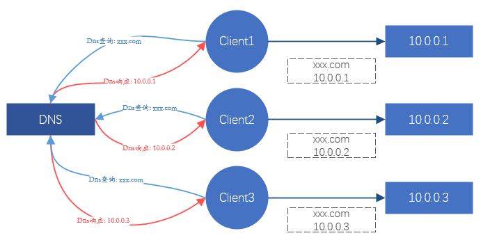
Figure 1. Schematic diagram of the effect of load balancing through DNS
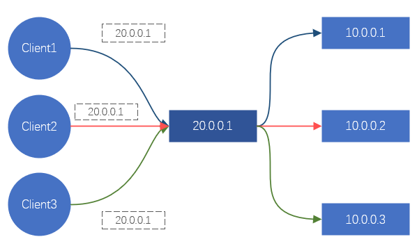
Figure 2. Schematic diagram of the effect of load balancing through LVS/Nginx
These two methods can achieve the effect of load balancing. But there is a serious problem here. Services such as DNS, Nginx, and LVS cannot provide services on a single machine in the Internet era. They are all clustered (that is, composed of N servers), so the reliability and stability of these clusters And how to guarantee it?
DNS is mainly responsible for domain name resolution, and has a certain load balancing effect, but the load effect is often very poor, so it is not the main consideration. Nginx provides Layer 7 load balancing, mainly relying on domain names for business differentiation and load. LVS is a layer 4 load balancing, mainly relying on TCP/UDP protocol, IP address, TCP/UDP port to distinguish services and loads.
In order to solve the load balancing and reliability of load balancer clusters such as Nginx and LVS, we can do the following simple solutions :
-
The load and reliability of the business server are guaranteed by Nginx;
-
The load and reliability of Nginx are guaranteed by LVS.
The above solution follows the logic of business <-- layer 7 load <-- layer 4 load , and actually implements two-level load in the application layer <-- transport layer in the network layered model . It can be seen that this solution actually uses another layer of load balancing to solve the load and reliability problems of the current layer. However, there are still problems with this solution. The load and reliability of the business layer and the Nginx cluster are guaranteed, but what about the reliability of the LVS cluster layer?
Since we have two levels of load in the application layer <-- transport layer in the network layered model , is it possible to achieve a three-level load of the application layer <-- transport layer <-- the network layer ? Fortunately, based on IP routing, network devices (switches, routers) naturally have the function of network layer load balancing.
At this point, we can implement the entire load balancing chain: business <-- layer 7 load (Nginx) <-- layer 4 load (LVS) <-- layer 3 load (NetworkDevices) ;
It can be seen from this that to ensure that the entire load balancing system is effective and reliable, it must be constructed from the network layer. Services at a high level can provide loads for services at a low level. Compared with the low-level business, the high-level business can be considered as the control plane of the low-level business, which can be implemented and managed by a professional team. The low-level business side only needs to focus on the realization of the business itself.
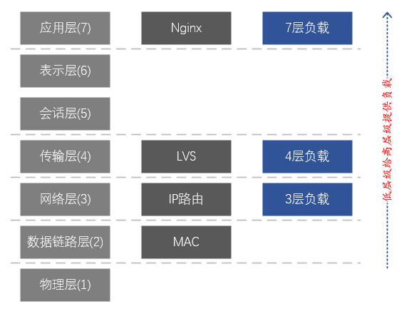
Figure 3. Correspondence between the 7-layer network model and LVS and Nginx
Description of the 7-layer layered model of the network:
7. Application layer: supports network applications. Application protocols are only a part of network applications. Processes running on different hosts use application layer protocols to communicate. The main protocols are: HTTP, FTP, Telnet, SMTP, POP3, etc.
6. Presentation layer: data representation, security, and compression. (In practice, this layer has been merged into the application layer)
5. Session layer: establish, manage, and terminate sessions. (In practice, this layer has been merged into the application layer)
4. Transport layer: Responsible for providing data transmission services between application programs for sources and destinations. This layer mainly defines two transport protocols, the Transmission Control Protocol (TCP) and the User Datagram Protocol (UDP).
3. Network layer: Responsible for sending datagrams independently from the source to the destination, mainly solving problems such as routing, congestion control and network interconnection.
2. Data link layer: responsible for encapsulating IP datagrams into frame formats suitable for transmission on the physical network and transmitting them, or decapsulating frames received from the physical network, taking out IP datagrams and handing them over to the network layer.
1. Physical layer: Responsible for transmitting the bit stream between nodes, that is, responsible for physical transmission. The protocol at this layer is related to both the link and the transmission medium.
3. How to implement Layer 4 load balancing
As mentioned above, the Layer 3 load is naturally provided by the network equipment, but in actual use it is tightly coupled with the Layer 4 load, and generally does not provide services independently. The Layer 4 load can directly provide services for the business layer without relying on the Layer 7 load (the Layer 7 load is mainly for services such as HTTP/HTTPS), so we mainly focus on the Layer 4 load here .
3.1 How to forward traffic
To achieve load balancing, the implication is to realize traffic redirection, so the first problem to be solved is how to forward traffic.
4 problems to solve:
① How to attract client traffic to the load balancer?
② How does the load balancer select a suitable backend server?
③ How does the load balancer send the request data to the backend server?
④ How does the backend server respond to the request data?
For ①,
The solution is very simple, to provide a batch of back-end servers with an independent IP address, which we call Virtual IP (also known as VIP). All clients do not need to directly access the back-end IP address, but instead access the VIP. For the client, it is equivalent to blocking the backend.
For ②,
Considering the versatility of low-level load balancing, complex load strategies are generally not implemented. Solutions like RR (round robin) and WRR (round robin with weight) are more suitable and can meet the requirements of most scenarios.
For ③,
The choice here will often affect the choice of ④. Ideally, we expect that the client's request data should be sent to the backend intact, so as to prevent the data packet from being modified. In the aforementioned seven-layer network layered model, the forwarding of the data link layer can be achieved without affecting the content of the upper-layer data packets, so it can be forwarded without modifying the data requested by the client. This is what the network often calls Layer 2 forwarding (data link layer, the second layer in the seven-layer network model), which relies on the MAC address addressing of the network card to forward data.
So, is it feasible to assume that the client's request data packet is packaged as a piece of application data and sent to the back-end server? This method is equivalent to establishing a tunnel between the load balancer and the backend, and transmitting the client's request data in the middle of the tunnel, so it can also meet the demand.
Among the above two solutions, the solution that relies on data link layer forwarding is called Direct Route (Direct Route) , that is, DR mode ; the other solution that requires a tunnel is called Tunnel mode . The DR mode has a disadvantage, because relying on MAC address forwarding, the backend server and the load balancer must be in the same subnet (it can not be strictly considered as the same network segment), which leads to the fact that only the same subnet as the load balancer Servers in the network can be accessed, and there is no opportunity to use load balancing if they are not in the same subnet. This is obviously impossible to meet the current large-scale business. The Tunnel mode also has disadvantages: since data forwarding depends on the tunnel, a tunnel must be established between the backend server and the load balancer. How to ensure that different business personnel can correctly configure the tunnel on the server and monitor the normal operation of the tunnel is very difficult. A complete management platform is required, which means that the management cost is too high.
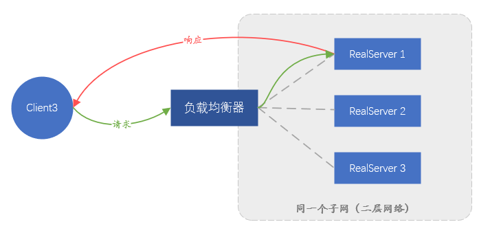
Figure 4. Schematic diagram of forwarding in DR mode, the response traffic will not pass through the load balancer
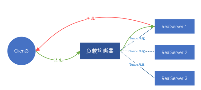
Figure 5. Schematic diagram of tunnel mode forwarding. Like DR, the response traffic will not pass through the load balancer
Since none of them are ideal, is there any other solution?
What we expect is that the back-end server does not perceive the existence of load balancing in the front-end, and the service can be placed anywhere without any excessive configuration. Since it is impossible to transmit the client's data packet intact, then proxy the client's request. That is, IP address translation is performed on the source IP and destination IP of the data packets sent by the client.
In detail, after receiving the request from client A, the load balancer initiates the same request to the backend server in the role of the client. The payload of the request comes from the request payload of client A, which ensures that the request data is consistent .
At this point, the load balancer is equivalent to initiating a new connection (different from the connection initiated by client A), and the new connection will use the IP address of the load balancer (called LocalIP) as the source address to directly contact the backend server IP communication.
When the backend returns data to the load balancer, the data is returned to client A through the connection of client A. The whole process involves two connections, corresponding to two IP address translations,
-
Request time: CIP→VIP, converted to LocalIP→backend server IP,
-
Data return time: backend server IP → LocalIP, converted to VIP → CIP.
The process of client forwarding data is completely based on IP address instead of MAC address. As long as the network is reachable, data can be transmitted smoothly between the client and the backend.
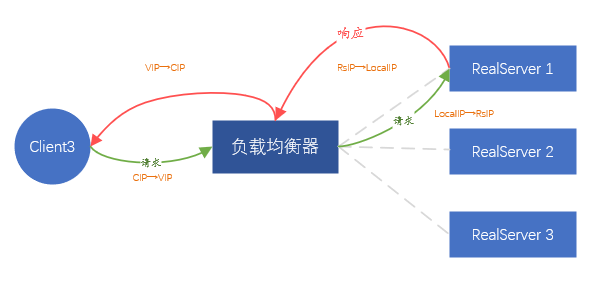
Figure 6. FULLNAT forwarding mode
The above solution is called FULLNAT forwarding mode , that is, two address translations are realized. Obviously, this method is simple enough, does not require any adjustments to the backend server, and does not limit where the backend is deployed. But there is also an obvious problem, that is, all the requests seen by the backend come from the load balancer, and the real client IP information is completely invisible, which is equivalent to blocking the real client. Fortunately, most applications in the data center do not need to know the IP address information of the real client. Even if the real client IP information is required, the load balancer can also load this part of the information into the TCP/UDP protocol data, through Install certain plug-ins as needed.
Based on the above solutions, the FULLNAT mode is the best for our business scenario (non-virtualized environment).
Since we intend to use the FULLNAT mode , there is no difficulty in solving ④, because the load balancer indirectly acts as the client, and all back-end data must be forwarded to the load balancer, and then sent to the real client by the load balancer end.
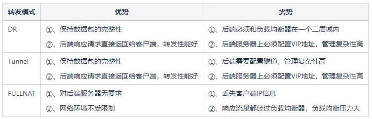
Table 1: Analysis of advantages and disadvantages among various modes
3.2 How to eliminate abnormal back-end servers
Load balancing generally provides a health check detection mechanism for the backend, so that abnormal backend IP addresses can be quickly eliminated. Ideally, semantic-based detection is the best, and it can more effectively detect whether the backend is abnormal. But this method will bring a lot of resource consumption, especially when the backend is huge; this is not particularly serious, the most serious thing is that the backend may run many kinds of HTTP, DNS, Mysql, Redis, etc. Protocols, management configurations are very diverse and too complex. The combination of the two problems makes the health check too cumbersome, which will occupy a lot of resources originally used for forwarding data, and the management cost is too high. Therefore, a simple and effective method is necessary. Since it is a Layer 4 load, we do not identify what the upstream business is, but only pay attention to whether the TCP or UDP port is reachable. The work of identifying the upper-layer business is handed over to the 7-layer load of Nginx type.
Therefore, as long as you regularly check whether all backend TCP/UDP ports are open, the backend service is considered normal if it is open, and the service is considered abnormal if it is not open. .
So how to detect it? Since it is only to judge whether the TCP port is normally open, we only need to try to establish a TCP connection. If the establishment is successful, it indicates that the port is normally open. But for UDP, because UDP is connectionless, there is no such thing as creating a new connection, but it can also achieve the purpose of detection by directly sending data. That is, send a piece of data directly, assuming that the UDP port is normally open, so the backend usually does not respond. If the port is not open, the operating system will return an icmp port unreachable status, which can be used to determine that the port is unreachable. But there is a problem. If the UDP detection packet contains a payload, it may cause the backend to think it is business data and receive irrelevant data.
3.3 How to implement load balancer fault isolation
As we said earlier, Layer 4 load balancing relies on network layer balancing to ensure that the load between Layer 4 load balancers is balanced, so the fault isolation of load balancers depends on the network layer.
How to do it?
In fact, we rely on routing for load balancing at the network layer. Each server in the load balancing cluster notifies the same VIP address to the network device (switch or router) through the routing protocol BGP, and the network device receives the same VIP address. If a VIP comes from different servers, an equal-cost route (ECMP) will be formed, and the implication is to form load balancing. So if we want to isolate a certain load balancer, we only need to revoke the VIP issued by the BGP routing protocol on the server, so that the upstream switch will think that the server has been isolated and will no longer forward data to the corresponding server. on the device.
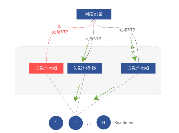
Figure 7. Fault isolation by withdrawing VIP routes
So far, we have implemented a load balancing architecture model based on FULLNAT, which mainly relies on Layer 3 protocol ports for health checks, and realizes VIP transceivers through BGP and network device docking.
4. Implementation of VGW
Based on the above-mentioned 4-layer load architecture, we built VGW (vivo Gateway), which mainly provides 4-layer load balancing services for intranet and extranet services. Next, we will explain the logical architecture, physical architecture, redundancy guarantee, and how to improve management forwarding performance.
4.1 VGW components
The core function of VGW is complex balancing, and it also has functions such as health check and business drainage. Therefore, the components that make up VGW are mainly the core load balancing forwarding module, health check module, and routing control module.
-
Load balancing forwarding module: mainly responsible for load calculation and data forwarding;
-
Health check module: mainly responsible for detecting the available status of the backend (RealServer), and clearing the unavailable backend in time, or restoring the available backend;
-
Routing control module: Mainly perform VIP release and drainage and isolate abnormal VGW servers.
4.2 Logical Architecture Scheme
For the convenience of understanding, we call the link from the client to the VGW the external network (External), and the link from the VGW to the backend (RealServer) is more complex than the internal network (Internal). In terms of logical architecture, the function of VGW is very simple, which is to evenly distribute the external business requests to the internal RealServer.
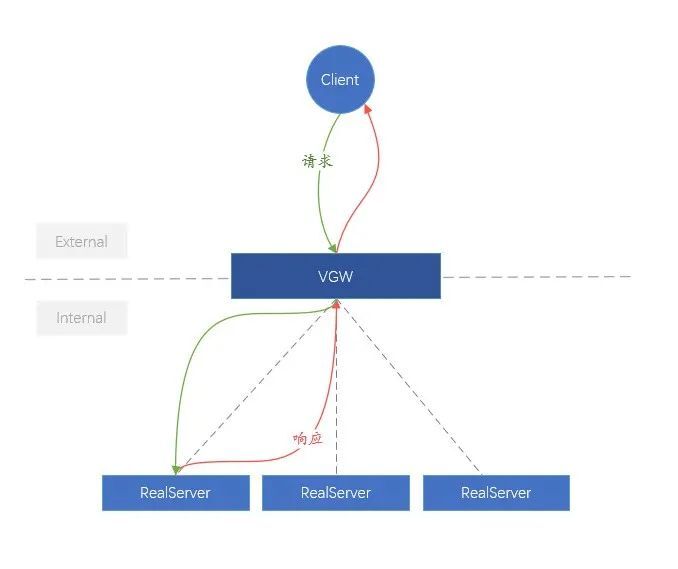
Figure 8. Logic diagram of VGW
4.3 Physical Architecture Scheme
In terms of physical architecture, there are certain differences between the VGW that provides the internal network and the VGW that provides the external network.
The external network VGW cluster uses at least two network cards, which are respectively connected to the network devices on the external network side and the network devices on the internal network side. For the VGW server, two network ports extend two links, similar to a pair of human arms, so this mode is called dual-arm mode , and a data packet only passes through a single network card of the VGW server once.
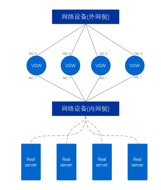
Figure 9. Physical diagram of external network VGW
The internal network VGW is different from the external network, and the internal network VGW only uses one network card to directly connect to the network equipment on the internal network side. Correspondingly, this method is called single-arm mode. A data packet needs to enter from only one network card first, then exit from the network card, and finally forward it to the outside, passing through the network card twice in total.
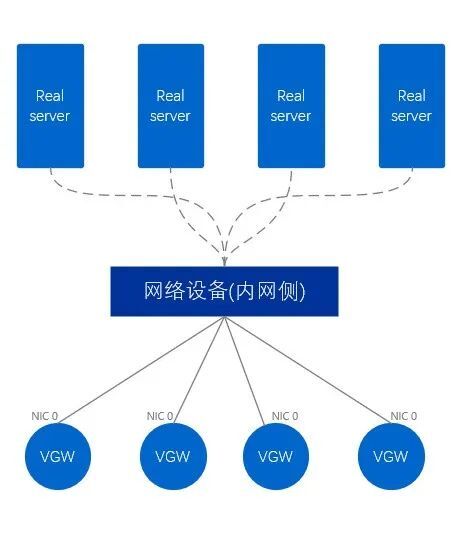
Figure 10. Physical diagram of intranet VGW
4.4 VGW Existing Business Model
As we said earlier, load balancing can provide a higher level of load balancing for Layer 7 loads.
-
At present, the largest business traffic of VGW comes from the traffic of the 7-layer access platform (that is, Nginx), and Nginx basically carries most of the company's core business.
-
Of course, Nginx can’t support all types of services. Layer 7 Nginx does not support the non-HTTP type of traffic built directly on top of TCP and UDP. Such services are directly forwarded to the service server by VGW, without other links in between. , such as Kafka, Mysql, etc.
-
Another part of the business is that users have built various proxy platforms, similar to Nginx, etc., but VGW also provides Layer 4 load balancing for them.
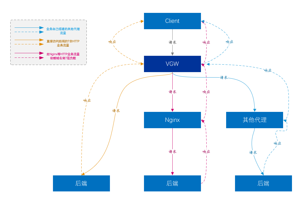
Figure 11. VGW business model diagram
4.5 VGW Redundancy Guarantee
In order to improve usability, what risks should be considered? Everyone naturally considers scenarios such as server failure and process failure. However, more needs to be considered in the VGW scenario, because the entire VGW system includes links, network devices, servers, processes, and so on. And we can't just consider the simple scenario of device downtime. In fact, the most troublesome situation is that any of the above-mentioned devices does not go down but forwards abnormally.
Therefore, monitoring whether the VGW service forwarding is normal is the first step. We regularly establish connections with VIPs through detection nodes deployed in different computer rooms and regions, and use the connection failure ratio as a standard to measure whether the VGW is normal. In fact, this monitoring is equivalent to detecting whether the links and forwarding of all links involving the VGW are good.
The above monitoring covers cluster-level detection. Of course, we have also established other finer-grained monitoring to find specific problems.
After monitoring first-hand data, we can provide server-level fault handling and cluster-level fault handling capabilities.
-
VGW automatically isolates the direct downtime of all equipment levels;
-
All link-level abnormalities, some of which can be automatically isolated;
-
All process-level exceptions can be automatically isolated;
-
For other abnormalities that are not complete failures, manual intervention is required to isolate them.
Server-level fault isolation means that some VGW servers will cancel the release of VIP through route adjustment, so as to achieve the purpose of isolation;
Cluster-level fault isolation is to unpublish the VIP of the entire VGW cluster, so that the traffic is automatically drawn by the standby cluster, and the standby cluster takes over all business traffic.
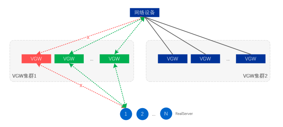
Figure 12. Server and link level fault isolation
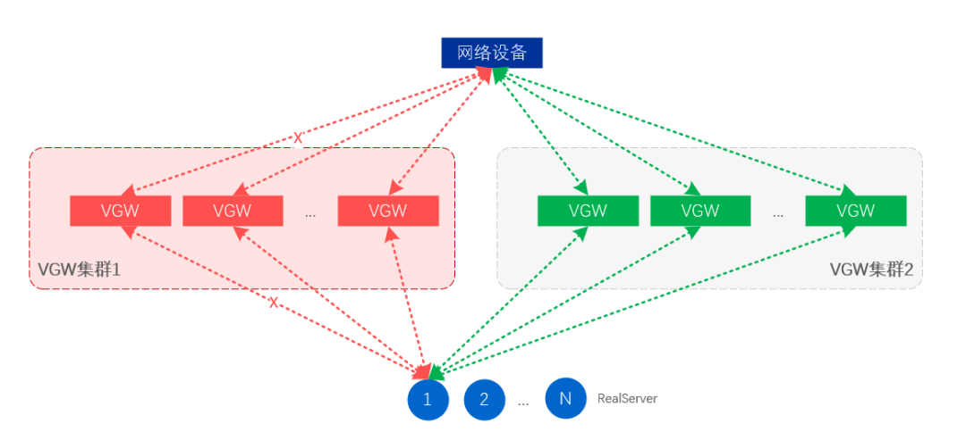
Figure 13. Fault isolation at the cluster level
4.6 How to improve VGW performance
As the volume of business becomes larger and larger, a single VGW needs to receive nearly one million QPS requests and at the same time achieve a packet processing capability of more than 500W/s. Obviously, general servers cannot achieve such a large number of requests and packet processing speeds. The main reason is the network processing mechanism of Linux. All network data packets must pass through the Linux kernel. After the network card receives the data packets, it must send an interrupt to the CPU, which will be processed by the CPU in the kernel, and then a copy will be copied to the application program. Sending data also needs to be processed by the kernel. Frequent interruptions and constant copying of data between user space and kernel space lead to serious consumption of CPU time in network data processing. The higher the packet rate, the worse the performance. Of course, there are other issues such as Cache Miss, cross-CPU data copy consumption, and so on.
It is easy to think here, can the dirty work done by the CPU above be thrown to the network card to do it, and the CPU can only process business data. At present, many solutions are based on this idea. The hardware solution includes smart network cards, and the pure software solution currently uses DPDK (Intel Data Plane Development Kit). Obviously, the cost of the smart network card will be high, and it is still in the development stage, and the application has a certain cost. DPDK pure software is much better in terms of cost and controllability. We chose DPDK as the underlying packet forwarding component (actually a secondary development based on iQIYI's open source DPVS).
DPDK mainly intercepts the packet processing process of the kernel, and directly sends user data packets to the application program instead of being processed by the kernel. At the same time, the behavior of relying on network card interruption to process data is discarded, and the method of polling is used to read data from the network card, so as to achieve the purpose of reducing CPU interruption. Of course, the CPU affinity is also used, and a fixed CPU is used to process network card data, reducing the consumption of process switching. In addition, there are many optimization technologies about Cache and memory. In general, the packet processing speed of the server network card can reach tens of millions of PPS, which greatly improves the packet processing capability of the network card, and then can increase the CPS (number of new connections per second) of the server. At present, we can achieve 100w+ CPS and 1200w+PPS business processing capacity under the 100G network card (test results under limited conditions, not theoretical values).
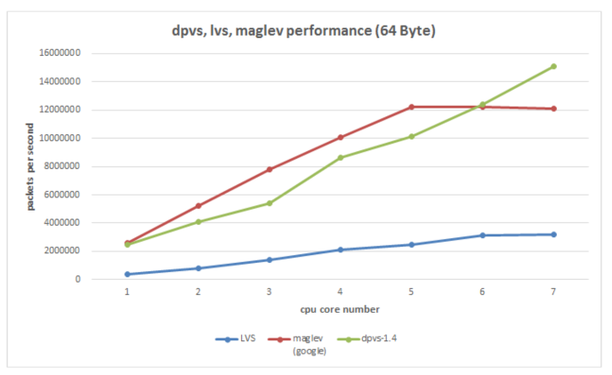
Figure 14. The underlying tool DPVS (DPDK+LVS) used by VGW compares the performance of several existing load balancing solutions
V. Summary
Through the above explanations, we gradually deduced a set of feasible load balancing solutions from a business reliability requirement, and combined with the actual needs of vivo, we implemented our VGW load balancing access platform. Of course, the current load balancing scheme is the result of a lot of trade-offs, and it is impossible to be perfect. At the same time, we will also face the problem of new business protocol support in the future, as well as the conflict between the decentralized business model of the data center and the centralized control of load balancing. But technology has been advancing, but there will always be a suitable solution!