聊过电源转化,太阳能充电,今天得聊聊电源自动切换电路,
实际中需要使用并且用过,那就来记录总结一下。
foreword
It’s time for a small class of circuits again. In actual product design, there are various power supply schemes. Here is an example of a general single-chip product. The system powered by about 3.3V is commonly powered by USB, external power adapter and battery.
In general product design, in order to make the product more stable and intelligent, we will reserve two or even multiple power supply methods. Generally, each power supply exists independently and can supply power to the product, but if these power supplies exist at the same time, they are How to choose the power supply or how should the designer design it into an ideal situation, this is the power supply automatic switching circuit that we are going to talk about today.
1. The simplest diode
The simplest power automatic switching circuit: diodes in parallel.
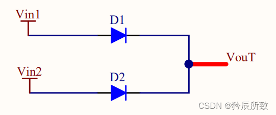
The two power supplies are automatically selected according to the level of the power supply voltage, which side is used with the higher voltage.
Diodes can be selected from ordinary diodes (max. 0.7V drop) or Schottky diodes (max. 0.3V drop)
1.1 are all 5V power supplies
If our system is powered by 3.3V, and both power sources are 5V (USB, external adapter), and an LDO needs to be connected at the back end, then it doesn't matter which diode is used in this circuit. If it is a common diode, pay attention to the LDO option. , you have to choose a low dropout.
If a 5V power supply is required in the system, then ordinary diodes are basically infeasible, and Schottky diodes must be used.
Using a 5V power supply through the Schottky diode voltage drop is fine for most devices that require a 5V power supply.
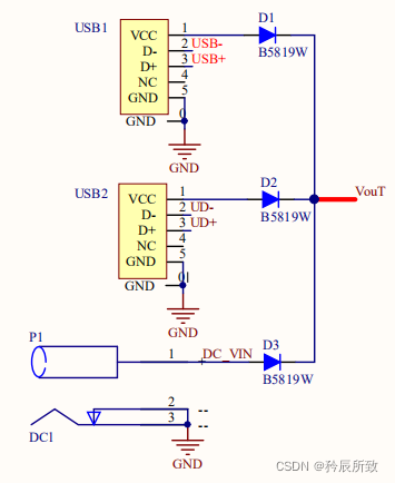
In this case, the use of diodes in parallel has an advantage, not limited to 2 circuits . For example, there may be 3 types in practice, and more can be used, but I have done a maximum of 3 circuits for a product, as shown in the following figure:
1.2 With battery power supply
However, if there is a power source that is a battery, whether it is a common 4.2V lithium battery or a 3.6V AA battery (there are lithium batteries, there are other types, such as lithium thionyl chloride batteries), it is obviously impossible to use a common diode with a 0.7V voltage drop. Then a Schottky diode must be chosen.
Even so, this voltage drop is too wasteful for the battery, but at least it can be used.
And we have to pay attention to a problem, the lower the voltage drop of the Schottky diode, but the larger the reverse leakage current, then in the case where the battery and other power sources exist at the same time, it is necessary to consider whether the battery can "tolerate" this reverse current. .
Most lithium batteries cannot receive current directly inflow. For the sake of safety, it is not recommended that batteries and 5V directly use this method as an automatic switching circuit. But in fact, if the product is used in a scenario, it is known that the battery and the external power supply may supply power together for very little time. Pay attention to the voltage required by your load and choose an appropriate LDO or power processing method. This method is practical.
Some people here may say, I know that the battery and the external power supply basically do not supply power together, why should I add a diode?
Here I am just speaking from experience. For dual power supplies, diodes must be added. Generally, Schottky diodes are added to reduce the voltage drop. It must not be added, because considering the safety of the product, the user's possible improper operation, etc.
1.3 Summary
Applicable scenarios, where the power supply is 5V, the power supply is an external adapter, USB, which is the most cost-effective solution.
There are many additional issues that need to be considered in battery scenarios. If you have a solid understanding of your product usage scenarios, you can use them accordingly.
2. MOS tube switching circuit
2.1 Classical circuit
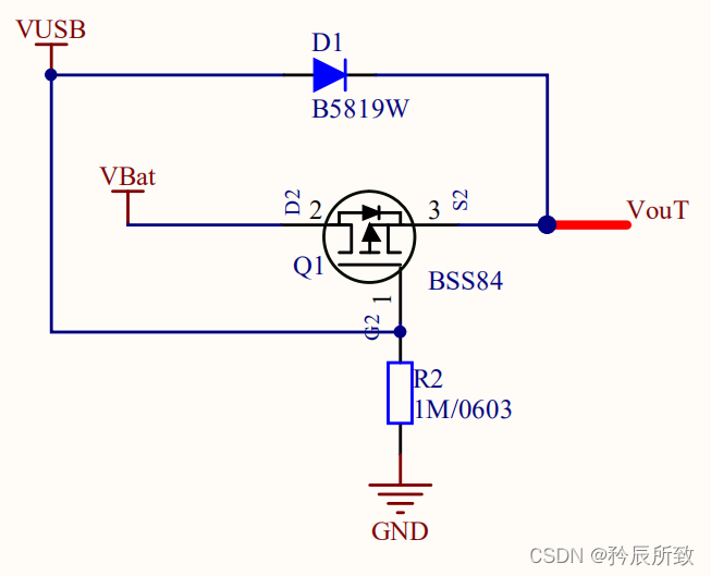
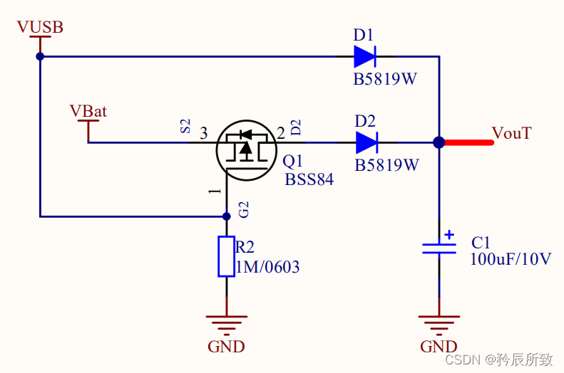
In the case of 5V power supply and battery, a MOS tube is used as a switch for the backup power supply (battery power supply). There is a classic circuit. The prototype is as follows (5V power supply does not have to be USB, but can be 5V from an external adapter):
This classic circuit has been introduced by many bloggers and engineers. By consulting a large number of articles, I found that most of them share a circuit and talk about the workflow. Here I have to point out a few things that are prone to error.
Note that the PMOS used here, the direction is not reversed, because the body diode of the MOS tube needs to be used. The battery voltage reaches the S-level through the body diode. When there is no VUSB, Vgs <0, the MOS transistor is turned on, and power is supplied to Vout.
Then why not point the S of the PMOS tube to VBat and the D-level to Vout?
Or because of the body diode, if there is VUSB, through the body diode, the VUSB voltage goes directly to the battery, which is not allowed.
The circuit flow is briefly introduced:
When VUSB is powered, the PMOS tube is turned off, even if the body diode current flows, but because VUSB will be higher than Vbat voltage, PMOS Vgs>0, so the PMOS body diode is cut off, and the load is powered by VUSB;
when VUSB is not powered, PMOS conducts On, the load is powered by VBat;
Is it possible to switch seamlessly and automatically?
Seamless automatic switching refers to whether the load can maintain normal operation without resetting or abnormality when one is suddenly removed when both VUSB and battery are powered at the same time. In fact, in most cases, it is possible to switch to the power supply without any problems after removing the VUSB.
Regarding this issue, it is actually quite complicated. There are many factors that determine whether seamless automatic switching can be performed. Generally, when using, some components are adjusted according to their own conditions to achieve seamless automatic switching. Here are some possible influences. Factors for seamless automatic switching:
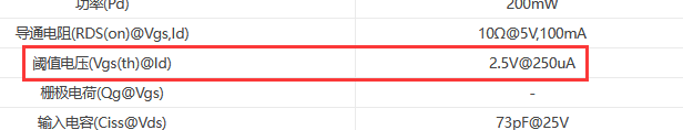
1. MOS tube parameters
We know that the MOS tube has a threshold voltage. The smaller the threshold voltage, the easier the MOS tube is turned on. When selecting the MOS tube, it can be adjusted according to the appropriate situation:
2. The R2 resistor in the above figure
In the above figure, there is a resistor R2 from the G pole of the MOS tube to GND. The smaller the resistance of this R2, the faster the conduction speed of the MOS tube.
But it should be noted that this R2 is always consuming power. If it is too small, the extra power consumption of the system will be wasted.
3. Filter capacitor at Vout end
In fact, if there is a larger filter capacitor on the Vout end, the capacitor can store a certain amount of energy, which will make the seamless switching more stable. The larger capacitors I actually use are at least 100uF or more.
4. Vin terminal capacitance
The capacitance at the Vin terminal is actually the capacitance at the VUSB inlet, which is absent in the above picture. Of course, it is proposed here to indicate that it is not recommended to add it, because the power-down of the VUSB is slower, resulting in a longer PMOS conduction time. The principle is the same as the filter capacitor for Vout above.
5. Load power consumption
We can't change the load power consumption, but it does affect the automatic switching. If the load power consumption is too large, it may cause the system to reset. Anyway, the greater the load power consumption, the easier it is to have problems when the power is switched. At this time, in general, you can try to increase the size of the filter capacitor at the Vout end.
So in actual use, pay attention to the above factors, the circuit can be seamlessly switched automatically.
The above circuit can actually be used normally in the dual power supply of VUSB and battery, and it is very classic and practical.
2.2 Classical circuit variants
We use PMOS in the classic circuit above, and also specifically mentioned the direction of PMOS, but if you just want to reverse the PMOS, or how to make up for it when you design it backwards?
Here is a variant circuit for the above circuit:
this circuit should be very simple to understand, the principle is that Vgs < 0, the PMOS tube is turned on, the same as the classic circuit above.
Then a D2 is added to prevent the possibility of VUSB charging the battery. The processing of this part is somewhat similar to the simplest diode parallel method mentioned above, but it is more reliable than the diode parallel connection.
Compared with the classic circuit, this circuit needs to accept the voltage drop of one more D2 diode from the battery.
This circuit has no advantages over classical circuits, but we need to understand this idea. With this idea, we have more possibilities. The previous two circuits are only applicable to the situation where Vbat must be less than VUSB. What if they have the same voltage or other situations? Of course, two diodes can be directly connected in parallel, but what we want to mention here is the method of using MOS.
2.3 Classic circuit upgrade
According to the previous classic circuit and the design idea of the classic circuit variant, we can use another MOS tube to replace D2, so the circuit becomes as follows:
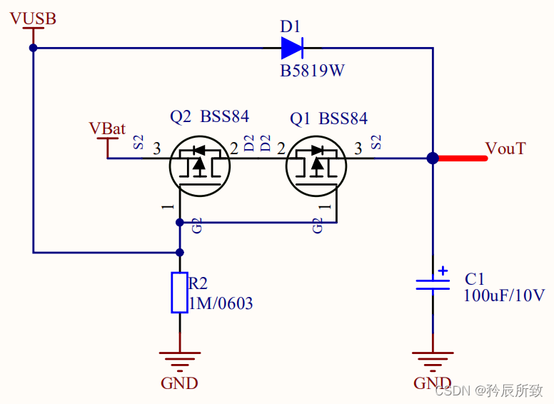
Compared with the above circuit, the voltage difference between VUSB and VBat is not so strict. The situation depends on the specific situation. The following logic is described according to the normal operation of the circuit design, of course not any voltage is suitable. We are only sharing circuit records here. If there are any problems, you can point them out in the comment area.
In principle, it is still a MOS tube. When VUSB is powered, Q2 and Q1 are turned off, and VUSB is powered. When VUSB is powered off, Q2 and Q1 are turned on, and VBat is powered.
Of course, it may be possible that Q2 will be turned on, and then Q1 will be turned off, and then the situation needs to be analyzed in detail according to the situation.
But on the whole, the voltage difference between VUSB and VBat is not so strict compared to the classic circuit, and switching can be done under the same voltage.
2.4 Another way of thinking
In addition to the above classic circuit ideas, I did use the above circuit in my project, but when writing a blog post, in order to make a summary, I searched a lot of articles and found a more favorite circuit:
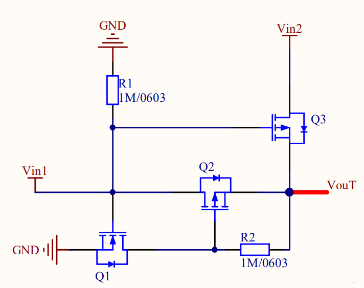
Here is the link to the original text: very delicate main and auxiliary power supply automatic switching circuit, and "zero" voltage drop, guest, have you got the essence? …
Where Vin1 is the main power supply and Vin2 is the backup power supply.
When Vin1 and Vin2 are both powered, Vin1 will be used. As long as there is Vin1, Q1 is turned on so that the G pole of Q2 is grounded, and then Q2 is also turned on. The G pole of Q3 is connected to Vin1, and the S pole is basically Vin1 (one smaller than Vin1). A little bit, tens of mV), so Q3 is off, and Vout comes from Vin1.
Other detailed analysis can view the original text, here I just make a record.
3. Power switch chip
For some special occasions, a power switch chip can also be used. The power switch chip has basically no voltage drop, but relatively speaking, the cost of the power switch chip is too high.
Such as the LTC441x family.
In the actual project, I really haven't used the power supply automatic switching chip. This may be recorded later when I have the opportunity to use it.
Epilogue
In addition to these common circuits mentioned in the article, there will be other circuits with triodes or more MOS transistors, but personally, I should not use so many components for a power switch = =! No matter how ingenious the circuit is, I basically seldom analyze it. I am still project-oriented. Unless it is really needed in the future, I will update the completed article.
The article is mainly based on summarizing and recording circuits, so detailed data analysis is not used. In actual use, according to your own situation, select the appropriate scheme and make necessary detailed adjustments in order to design a suitable circuit scheme for yourself!
thank you all!