Campus network simulation
-
Preface
Some time ago, the subject of "Computer Networks" began to write experiments. Although there are only three experiments, one is more troublesome than one.
The content of the second experiment is to write a simulation experiment with Cisco simulation software. Although I know Cisco, I never know what simulation software Cisco has. The teacher let us fend for ourselves. No way, I had to look up the information myself.
However, I searched for a lot of information and found that either there was an error or something was missing there. Later, I simply stopped referring to those tutorials written by others. I started looking for the manual for this software, researched it myself, and studied it for a long time, and finally got some results.
I sent it out today, hoping to give some help to those who are struggling to find information to no avail and suffering.
-
demand analysis
-
range
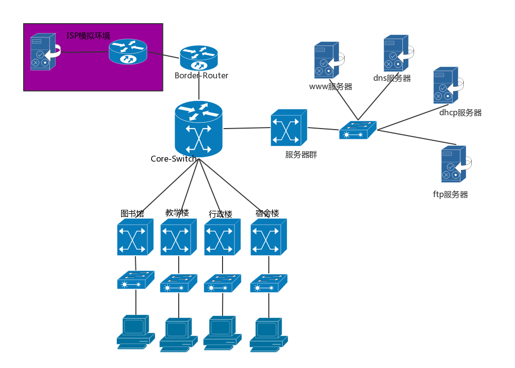
The scope here refers to the campus network contains several areas.
University campus is really a more complex network, but after all, there is only a small simulation of the campus network, there is no need to do too complicated, here I set up a server farm, student dormitories, administrative buildings, teaching buildings, libraries five This area is enough to understand the structure of the campus network. -
Features
- The school has a large number of students and insufficient IP addresses, so there will definitely be a DHCP server dynamically assigning IP addresses.
- Each school has its own official website, so a www server is inevitably needed.
- Set up an education mailbox and use an Email server.
- An ftp server is sometimes needed.
- The DNS server provides domain name conversion services.
- The host of the local area network needs to communicate with the external network, using the NAT translation protocol.
-
-
Overall design
-
Topology
The main topological structures of computer networks are bus topology, ring topology, tree topology, star topology, hybrid topology and mesh topology. Among them, ring topology, star topology, and bus topology are the three most basic topologies. In the local area network, the most used is the star structure. The topology I used here is also a star topology . For more information about the topology, please click on the topology .
It looks like this:
-
层级结构
层级结构采用的是三层结构: -
使用的设备
 普通的PC
普通的PC
-
-
详细设计
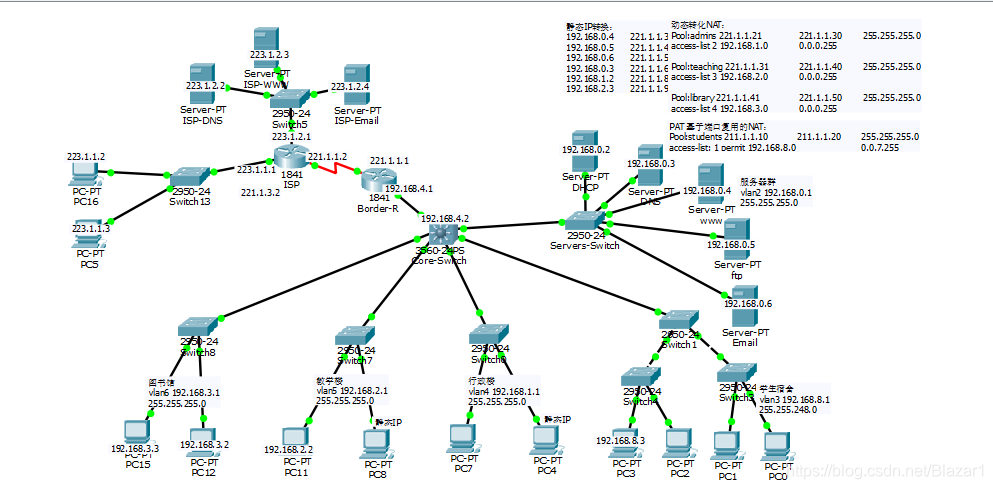
先放一张总图:
我会逐步添加设备,同时附上代码。-
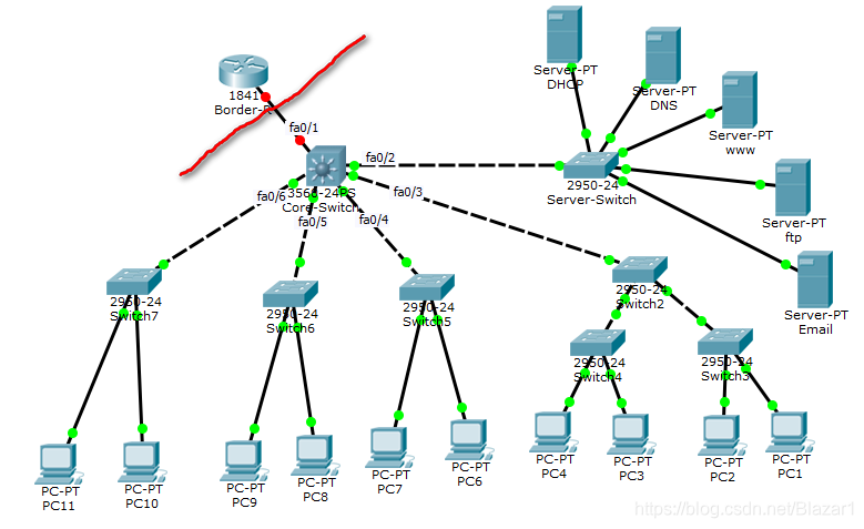
连接基本线路
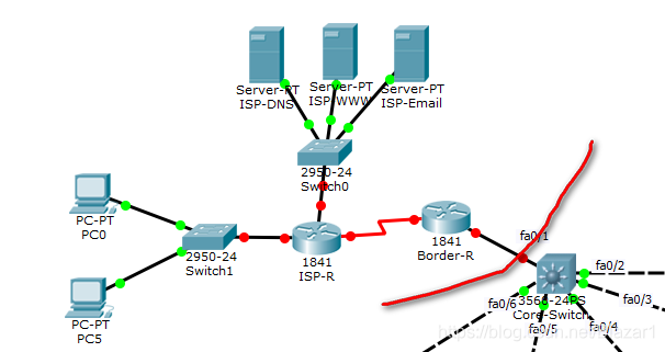
红线右边的就是校园网部分,左边的路由器是边缘路由器(Border-R)。
-
配置Vlan
vlan的全称是 virtual local area network,即虚拟局域网。它可以使一组设备和用户之间相互通信,好像它们是在同一个网段中一样。
IEEE于1999年颁布了用于标准化VLAN实现方案的802.1Q协议标准草案。VLAN技术的出现,使得管理员根据实际应用需求,把同一物理局域网内的不同用户逻辑地划分成不同的广播域,每一个VLAN都包含一组有着相同需求的计算机工作站,与物理上形成的LAN有着相同的属性。由于它是从逻辑上划分,而不是从物理上划分,所以同一个VLAN内的各个工作站没有限制在同一个物理范围中,即这些工作站可以在不同物理LAN网段。由VLAN的特点可知,一个VLAN内部的广播和单播流量都不会转发到其他VLAN中,从而有助于控制流量、减少设备投资、简化网络管理、提高网络的安全性。
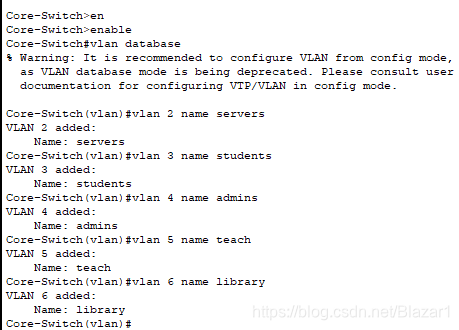
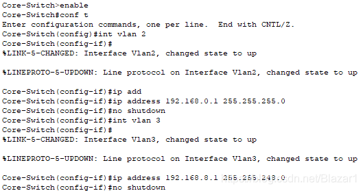
我在这里设置了5个vlan,分别是服务器群、学生宿舍局域网(简称学生宿舍)、教学楼、行政楼、图书馆。它们的vlan网段分布如下表所示:
vlan名称 对应区域 网段 掩码 vlan2 服务器群 192.168.0.1 255.255.255.0 vlan3 学生宿舍 192.168.8.1 255.255.248.0 vlan4 行政楼 192.168.1.1 255.255.255.0 vlan5 教学楼 192.168.2.1 255.255.255.0 vlan6 图书馆 192.168.3.1 255.255.255.0 -
配置VTP:
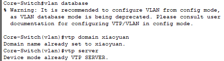
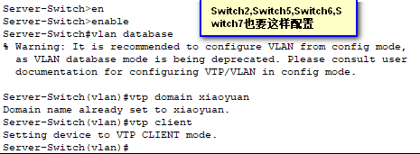
说明:VTP(Vlan Trunk Protocol) 即VLAN中继协议。VTP通过网络(ISL 帧 或cisco 私有DTP帧) 保持VLAN配置统一性。VTP在系统级管理增加,删除,调整的VLAN,自动地将信息向网络中其它的交换机广播。此外, VTP减小了那些可能导致安全问题的配置。便于管理, 只要在vtp server 做相应设置,vtp client 会自动学习vtp server 上的vlan 信息。 -
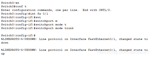
配置中继
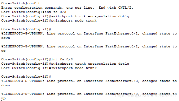
说明:配置中继,使VTP管理域能够覆盖所有的分支交换机。Trunk是一个在交换机之间、交换机与路由器之间传递VLAN信息和VLAN数据流的协议,将交换机之间的相连的端口配置为dot1q封装,就可跨越交换机进行整个网络的VLAN设置。
注意:fa 0/2~fa 0/6都要进行这样的配置! -
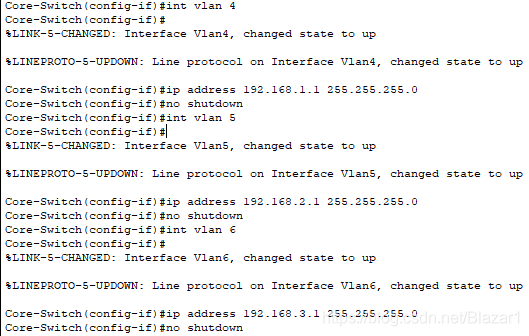
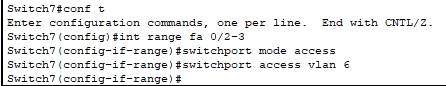
创建vlan及端口划分
其实创建vlan也可以在 config>vlan数据库 设置
-
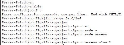
配置服务器群交换机
-
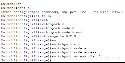
配置学生宿舍交换机
-
配置行政楼交换机
-
配置教学楼交换机
-
配置图书馆交换机
-
配置主机IP地址
配置主机IP地址有两种方式:1.静态IP地址(手动设置)2.动态IP(依靠DHCP服务器来实现),由于需要,这两种方式都会用到。
-
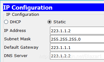
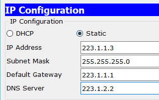
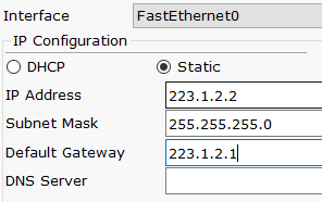
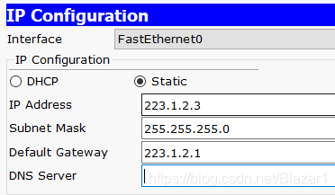
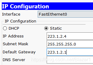
手动设置IP
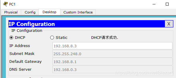
The server's IP must be static, and generally speaking, the PCs in the teaching building and the administration building use static IP addresses. Therefore, I configure PC6 and PC8 as static IPs, and the rest are set to dynamic IPs.
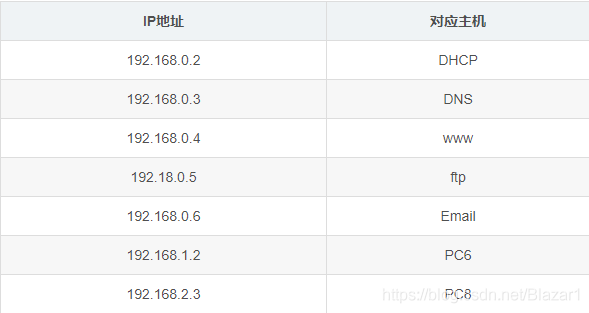
Find Desktop>IP Congiguration to configure, as shown in the figure:
-
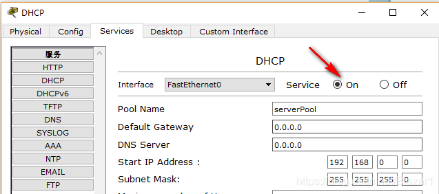
DHCP server configuration
First turn on the DHCP service, as shown below:
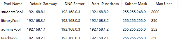
Add these IP pools:
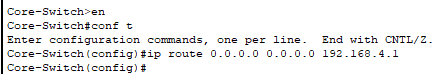
Then set the central switch to point to the DHCP server:
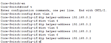
Finally, turn on the routing function of the central switch:

test:
At this point, each network segment in the campus network can communicate with each other. Next we start to build an external network.
-
Build an extranet
Connect the line first:
Note: Before connecting the line between ISP-R and Border-R , you need to add the WIC-2T module first . -
Set IP address
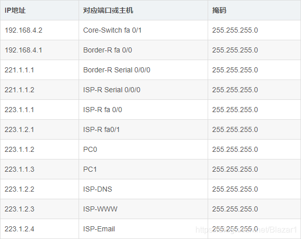
The first line: the
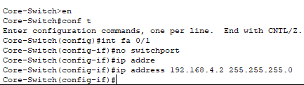
second line: the
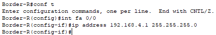
third line: the
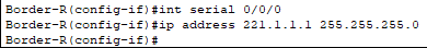
fourth line: the
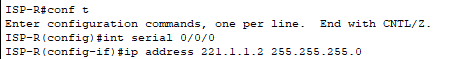
fifth line: the

sixth line: the

seventh line: the
eighth line: the
ninth line (remember to turn on the DNS service): the
tenth line (remember to turn on the HTTP service) : The
eleventh line (remember to turn on the Email service):
-
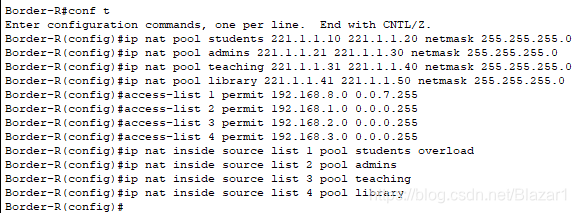
Configure NAT
There are three ways to implement NAT: static conversion Static Nat, dynamic conversion Dynamic Nat, and port multiplexing Overload. I have used three methods here:
-
Static conversion
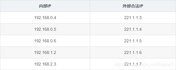
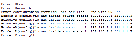
-
Dynamic conversion
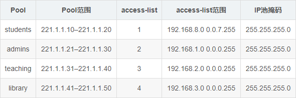
Among them, students use port multiplexing technology.Nat settings
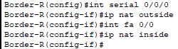
Next specify the internal port and external port:
Configure routing: a

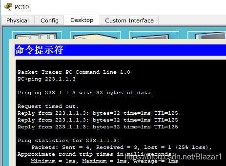
simple test, use PC10 to ping PC5:
-
Configure the server
-
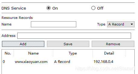
DNS server
The configuration of the DNS server is very simple, just add some records. E.g:
-
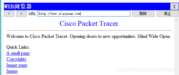
HTTP server
Just turn on the service.
Enter the URL in Web Browserh on the PC:
The configuration of other servers is also very simple, you can explore the configuration yourself.
-
It ends here!
Attach a little reference material I found.
(Update link 2020-06-23)
Link: https://pan.baidu.com/s/1ifN7LNxh-GiY0o5UjGRpkQ Extraction code: u47u
I have put the pkt file in the link above.
Campus network simulation
-
Preface
Some time ago, the subject of "Computer Networks" began to write experiments. Although there are only three experiments, one is more troublesome than one.
The content of the second experiment is to write a simulation experiment with Cisco simulation software. Although I know Cisco, I never know what simulation software Cisco has. The teacher let us fend for ourselves. No way, I had to look up the information myself.
However, I searched for a lot of information and found that either there was an error or something was missing there. Later, I simply stopped referring to those tutorials written by others. I started looking for the manual for this software, researched it myself, and studied it for a long time, and finally got some results.
I sent it out today, hoping to give some help to those who are struggling to find information to no avail and suffering.
-
demand analysis
-
range
The scope here refers to the campus network contains several areas.
University campus is really a more complex network, but after all, there is only a small simulation of the campus network, there is no need to do too complicated, here I set up a server farm, student dormitories, administrative buildings, teaching buildings, libraries five This area is enough to understand the structure of the campus network. -
Features
- The school has a large number of students and insufficient IP addresses, so there will definitely be a DHCP server dynamically assigning IP addresses.
- Each school has its own official website, so a www server is inevitably needed.
- Set up an education mailbox and use an Email server.
- An ftp server is sometimes needed.
- The DNS server provides domain name conversion services.
- The host of the local area network needs to communicate with the external network, using the NAT translation protocol.
-
-
Overall design
-
Topology
The main topological structures of computer networks are bus topology, ring topology, tree topology, star topology, hybrid topology and mesh topology. Among them, ring topology, star topology, and bus topology are the three most basic topologies. In the local area network, the most used is the star structure. The topology I used here is also a star topology . For more information about the topology, please click on the topology .
It looks like this:
-
Hierarchical structure
The hierarchical structure uses a three-tier structure:-
Core layer:
The central computer room is equipped with a gigabit core switch, which is responsible for data exchange within the entire campus network. -
Convergence layer:
Set up secondary switch nodes in teaching buildings, dormitory buildings, libraries, and administrative buildings. -
Access layer:
The entire campus network has only one external network exit, that is, the core switch is connected to the edge router, and the edge router is connected to the WAN equipment.
Note: The role of the convergence layer is to gather the switches below and share a line to connect to the central switch, so as to prevent the central switch from connecting too many lines. In fact, this hierarchical structure is a tree structure.
-
-
Equipment used
-
Core layer
Using a three-tier switch, in this version of the Cisco simulator, I use
-
Convergence layer
Just use an ordinary switch. E.g:

-
Access layer
Ordinary PC -
-
-
detailed design
First put a general picture:
I will gradually add equipment, and attach the code at the same time.-
Connect the basic line
The right side of the red line is the campus network, and the left router is the border router (Border-R).
-
Configure VLAN
vlan的全称是 virtual local area network,即虚拟局域网。它可以使一组设备和用户之间相互通信,好像它们是在同一个网段中一样。
IEEE于1999年颁布了用于标准化VLAN实现方案的802.1Q协议标准草案。VLAN技术的出现,使得管理员根据实际应用需求,把同一物理局域网内的不同用户逻辑地划分成不同的广播域,每一个VLAN都包含一组有着相同需求的计算机工作站,与物理上形成的LAN有着相同的属性。由于它是从逻辑上划分,而不是从物理上划分,所以同一个VLAN内的各个工作站没有限制在同一个物理范围中,即这些工作站可以在不同物理LAN网段。由VLAN的特点可知,一个VLAN内部的广播和单播流量都不会转发到其他VLAN中,从而有助于控制流量、减少设备投资、简化网络管理、提高网络的安全性。
我在这里设置了5个vlan,分别是服务器群、学生宿舍局域网(简称学生宿舍)、教学楼、行政楼、图书馆。它们的vlan网段分布如下表所示:
vlan名称 对应区域 网段 掩码 vlan2 服务器群 192.168.0.1 255.255.255.0 vlan3 学生宿舍 192.168.8.1 255.255.248.0 vlan4 行政楼 192.168.1.1 255.255.255.0 vlan5 教学楼 192.168.2.1 255.255.255.0 vlan6 图书馆 192.168.3.1 255.255.255.0 -
配置VTP:
说明:VTP(Vlan Trunk Protocol) 即VLAN中继协议。VTP通过网络(ISL 帧 或cisco 私有DTP帧) 保持VLAN配置统一性。VTP在系统级管理增加,删除,调整的VLAN,自动地将信息向网络中其它的交换机广播。此外, VTP减小了那些可能导致安全问题的配置。便于管理, 只要在vtp server 做相应设置,vtp client 会自动学习vtp server 上的vlan 信息。 -
配置中继
Description: Configure the relay so that the VTP management domain can cover all branch switches. Trunk is a protocol for transferring VLAN information and VLAN data flow between switches and between switches and routers. Configure the connected ports between switches as dot1q encapsulation, and then VLAN settings of the entire network can be performed across switches.
Note: fa 0/2~fa 0/6 must be configured like this! -
Create vlan and port division
In fact, you can also create vlan in config> vlan database settings
-
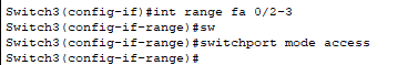
Configure the server farm switch
-
Configure student dormitory switch
-
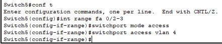
Configure the administrative building switch
-
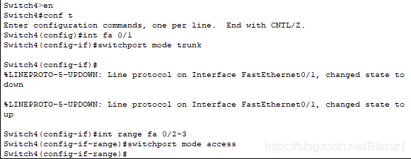
Configure the school building switch
-
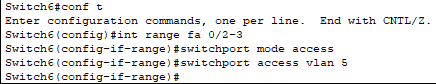
Configure library switches
-
Configure the host IP address
There are two ways to configure the host IP address: 1. Static IP address (manual setting) 2. Dynamic IP (rely on DHCP server to achieve), due to need, both methods will be used.
-
Set IP manually
The server's IP must be static, and generally speaking, the PCs in the teaching building and the administration building use static IP addresses. Therefore, I configure PC6 and PC8 as static IPs, and the rest are set to dynamic IPs.
Find Desktop>IP Congiguration to configure, as shown in the figure: -
DHCP server configuration
First turn on the DHCP service, as shown below:
Add these IP pools:
Then set the central switch to point to the DHCP server:
Finally, turn on the routing function of the central switch:
test:
At this point, each network segment in the campus network can communicate with each other. Next we start to build an external network.
-
Build an extranet
Connect the line first:
Note: Before connecting the line between ISP-R and Border-R , you need to add the WIC-2T module first . -
Set IP address
The first line: the
second line: the
third line: the
fourth line: the
fifth line: the
sixth line: the
seventh line: the
eighth line: the
ninth line (remember to turn on the DNS service): the
tenth line (remember to turn on the HTTP service) : The
eleventh line (remember to turn on the Email service):
-
Configure NAT
There are three ways to implement NAT: static conversion Static Nat, dynamic conversion Dynamic Nat, and port multiplexing Overload. I have used three methods here:
-
Static conversion
-
Dynamic conversion
Among them, students use port multiplexing technology.Nat settings
Next specify the internal port and external port:
Configure routing: a
simple test, use PC10 to ping PC5:
-
Configure the server
-
DNS server
The configuration of the DNS server is very simple, just add some records. E.g:
-
HTTP server
Just turn on the service.
Enter the URL in Web Browserh on the PC:
The configuration of other servers is also very simple, you can explore the configuration yourself.
-
It ends here!
Attach a little reference material I found.
(Update link 2020-06-23)
Link: https://pan.baidu.com/s/1ifN7LNxh-GiY0o5UjGRpkQ Extraction code: u47u