Article Directory
1. Introduction to Ultrasonic Module
Ultrasonic modules generally use HC-SR04 for ranging
1) Product features
HC-SR04 ultrasonic ranging 2cm-400cm module may provide non-contact distance sensing function, measured
from a high precision up to the non-contact distance sensing function, high ranging accuracy up to 3mm; ultrasonic wave emitting module comprising Receiver, receiver and control circuit.
2) Basic working principle
(1) Use the IO port TRIG to trigger the ranging, and give a high-level signal of at least 10us.
(2) module automatically sends eight 40khz square wave, and automatically detects whether a signal is returned;
(3) a signal is returned, through the IO port ECHO outputs a high level, the high level duration time is an ultrasonic
wave emitted to return from time. Test distance = (high level time * speed of sound (340M/S))/2;
3) Physical map

Wiring as shown on the right,
- Vcc: +5V power supply
- Trig: input trigger signal (can trigger ranging)
- Echo: Outgoing signal echo (time difference can be returned)
- Gnd: Ground
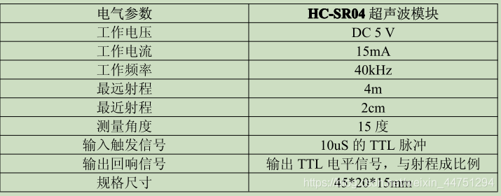
4) Electrical parameters
2. Principle of Ultrasonic Module
1) Ultrasonic timing chart
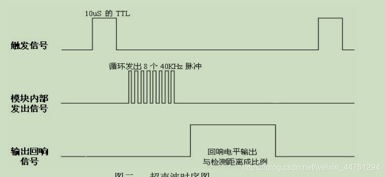
The above sequence diagram shows that you only need to provide a pulse trigger signal above 10uS, and the module will send out 8 40kHz cycle levels and detect echoes. Once the echo signal is detected, the echo signal is output. The pulse width of the echo signal is proportional to the measured distance. Therefore, the distance can be calculated from the time interval between the transmitted signal and the received echo signal. Formula: uS/58=cm or uS/148=inch; or: distance=high level time*speed of sound (340M/S)/2; the recommended measurement period is 60ms or more to prevent the influence of the transmitted signal on the echo signal.
Note:
1. This module should not be connected with electricity. If you want to connect with electricity, please connect the GND terminal of the module first, otherwise it will affect the normal operation of the module.
2. When measuring the distance, the area of the measured object is not less than 0.5 square meters and the plane should be as flat as possible, otherwise the measurement result will be affected
2) Implementation ideas
-
1. Give trig high level directly, and then read whether the ECHO pin is high level, if it is high level, start the timer, and then continue to detect when it is low level, get the counter value, and then proceed Calculation
-
2. To turn on the external interrupt, first configure the rising edge interrupt in ECHO. When the interrupt comes, start the timer in the interrupt function, and then configure it as a falling edge interrupt, and wait for the falling edge interrupt to get the counter value.
In fact, in the above two methods, the idea is to calculate the distance by calculating the counter value of the timer.
- 3. Timer channel PWM control trigger and trigger cycle, the high level time of ultrasonic return signal is obtained by timer channel capture function
For the use of timer input capture, please refer to my other articles: Introduction to the use of TIM timers
3. Reference code
1) stm8 is based on TIM1's ch1 input capture implementation
// 关于超声波测距的宏定义
#define HCSR04_TRIG PC_ODR_ODR0  //PC0为TRIG,输出10us的高电平
#define HCSR04_ECHO PC_IDR_IDR1  //PC1为ECHO,输入一个脉冲信号
#define SYS_CLOCK   16000000     //定义系统当前fmaster频率值15797600UL。

//获取距离的函数
float Hcsr04_getdistance(void)
{
    u16 B_num = 0;
    u32 Time = 0;
    float Distance = 0;

      HCSR04_TRIG = 0;
//   printf("准备开始测试...\n");

    //   TIM1_CCR1H=0x00;//清除捕获/比较寄存器1高8位
 //   TIM1_CCR1L=0x00;//清除捕获/比较寄存器1低8位
    TIM1_SR1&=0xF9;//清除CC1IF标志位与CC2IF标志位
    TIM1_SR2&=0xF9;//清除CC1OF标志位与CC2OF标志位
    TIM1_CCER1|=0x11;//捕获功能使能
 //   printf("捕获功能开启,等待ECHO信号...\n");

     //TRIG给最少 10us 的高电平信呈
      HCSR04_TRIG = 1;
      delay_10us(5);
      HCSR04_TRIG = 0;
   //   overflow_count = 0;
  //    printf("TRIG已发送 10uS 以上脉冲触发信号...\n");

     while((TIM1_SR1&0x02)==0);//等待捕获比较1标志位CC1IF变为“1”
  //   TIM1_CR1|=0x01;        //使能TIM1计数器功能“CEN=1”
  //   printf("上升沿信号捕获...\n");

    while((TIM1_SR1&0x04)==0);//等待捕获比较2标志位CC2IF变为“1”
 //   printf("下降沿信号捕获...\n");

    //取出数据CC2IF位就自动清0
    B_num=(u16)TIM1_CCR2H<<8;//取回捕获/比较寄存器2高8位
    B_num|=TIM1_CCR2L;//取回捕获/比较寄存器2低8位并与高8位拼合
 //   printf("B_num:%d\n",B_num);

   // TIM1_SR1&=0xFB;//清除CC2IF标志位

     Time = B_num*1000000/SYS_CLOCK; //脉冲长度单位为us
  //   printf("Time:%d\n",Time);

     Distance = B_num/16.05*0.017;
 //    printf("Distance:%f cm\n",Distance);


     TIM1_CCER1&=0xEE;//捕获功能禁止

     return Distance;
}


/****************************************************************/
//TIM1功能初始化函数TIM1_init(),无形参,无返回值
/****************************************************************/
void TIM1_init(void)
{
  //1.CC1通道被配置为输入,IC1映射在TI1FP1上“CC1S[1:0]=01”
  // 0x000000001 : CC1通道被配置为输入,IC1映射在TI1FP1上;
  TIM1_CCMR1|=0x01;

  //2.配置TI1FP1信号边沿极性为上升沿“CC1P=0”
  // 0x11111101 : 捕获发生在TI1F或TI2F的上升沿;
  TIM1_CCER1&=0xFD;

  //3.CC2通道被配置为输入,IC2映射在TI1FP2上“CC2S[1:0]=10”
  // 0x00000010 : CC2通道被配置为输入,IC1映射在TI2FP2上;
  TIM1_CCMR2|=0x02;

  //4.配置TI1FP2信号边沿极性为下降沿“CC2P=1”
  // 0x00100000 : 1:捕获发生在TI1F或TI2F的下降沿
  TIM1_CCER1|=0x20;

  //5.配置触发输入信号为TI1FP1,“TS[2:0]=101”
  // 0x01010000 : 选择用于选择同步计数器的触发输入,滤波后的定时器输入1(TI1FP1)
  TIM1_SMCR|=0x50;

  //6.配置触发模式为复位触发,“SMS[2:0]=100”
  // 0x00000100 : 复位模式 – 在选中的触发输入(TRGI)的上升沿时重新初始化计数器,并且产生一个更新寄存器的信号
  TIM1_SMCR|=0x04;

  //7.使能TIM1计数器功能“CEN=1”
  TIM1_CR1|=0x01;

  //没有设置在外部触发寄存器(TIM1_ETR)中的采样频率
}

//初始化
void HCSR04_Init(void)
{
  //PC1为ECHO,PC0为TRIG
    //设置TRIG引脚为PC0,TRIG输出一个10us的高电平触发
    PC_DDR_DDR0 = 1;
    PC_CR1_C10 = 1;
    PC_CR2_C20 = 0;

    //设置ECHO引脚为PC1,ECHO输入一个脉冲信号,需要用定时器测出持续时间

    PC_DDR_DDR1 = 0;  //设置为PC1为输入
    PC_CR1_C11 = 1;   //设置诶上拉输入
    PC_CR2_C21 = 0;   //带中断


 /*
    PC_DDR_DDR1 = 0;  //设置为PD2为输入
    PC_CR1_C11 = 1;   //设置诶上拉输入
    PC_CR2_C21 = 1;   //带中断
  */
}
2) 51 realizes ranging and uses digital tube display (provided by Taobao)
//超声波测距
//晶振=8M
//MCU=STC10F04XE
//P0.0-P0.6共阳数码管引脚
//Trig  = P1^0
//Echo  = P3^2
#include <reg52.h>     //包括一个52标准内核的头文件
#define uchar unsigned char //定义一下方便使用
#define uint  unsigned int
#define ulong unsigned long
//***********************************************
sfr  CLK_DIV = 0x97; //为STC单片机定义,系统时钟分频
                     //为STC单片机的IO口设置地址定义
sfr   P0M1   = 0X93;
sfr   P0M0   = 0X94;
sfr   P1M1   = 0X91;
sfr   P1M0   = 0X92;
sfr	P2M1   = 0X95;
sfr	P2M0   = 0X96;
//***********************************************
sbit Trig  = P1^0; //产生脉冲引脚
sbit Echo  = P3^2; //回波引脚
sbit test  = P1^1; //测试用引脚

uchar code SEG7[10]={0xC0,0xF9,0xA4,0xB0,0x99,0x92,0x82,0xF8,0x80,0x90};//数码管0-9
uint distance[4];  //测距接收缓冲区
uchar ge,shi,bai,temp,flag,outcomeH,outcomeL,i;  //自定义寄存器
bit succeed_flag;  //测量成功标志
//********函数声明
void conversion(uint temp_data);
void delay_20us();
//void pai_xu();

void main(void)   // 主程序
{  uint distance_data,a,b;
   uchar CONT_1;
   CLK_DIV=0X03; //系统时钟为1/8晶振(pdf-45页)
     P0M1 = 0;   //将io口设置为推挽输出
     P1M1 = 0;
     P2M1 = 0;
     P0M0 = 0XFF;
     P1M0 = 0XFF;
     P2M0 = 0XFF;
   i=0;
   flag=0;
	test =0;
	Trig=0;       //首先拉低脉冲输入引脚
	TMOD=0x11;    //定时器0,定时器1,16位工作方式
	TR0=1;	     //启动定时器0
   IT0=0;        //由高电平变低电平,触发外部中断
	ET0=1;        //打开定时器0中断
 //ET1=1;        //打开定时器1中断
	EX0=0;        //关闭外部中断
	EA=1;         //打开总中断0


while(1)         //程序循环
	{
  EA=0;
	     Trig=1;
        delay_20us();
        Trig=0;         //产生一个20us的脉冲,在Trig引脚
        while(Echo==0); //等待Echo回波引脚变高电平
	     succeed_flag=0; //清测量成功标志
	     EX0=1;          //打开外部中断
	 	  TH1=0;          //定时器1清零
        TL1=0;          //定时器1清零
	     TF1=0;          //
        TR1=1;          //启动定时器1
   EA=1;

      while(TH1 < 30);//等待测量的结果,周期65.535毫秒(可用中断实现)
		  TR1=0;          //关闭定时器1
        EX0=0;          //关闭外部中断

    if(succeed_flag==1)
	     {
		   distance_data=outcomeH;                //测量结果的高8位
           distance_data<<=8;                   //放入16位的高8位
		     distance_data=distance_data|outcomeL;//与低8位合并成为16位结果数据
            distance_data*=12;                  //因为定时器默认为12分频
           distance_data/=58;                   //微秒的单位除以58等于厘米
         }                                      //为什么除以58等于厘米,  Y米=(X秒*344)/2
			                                       // X秒=( 2*Y米)/344 ==》X秒=0.0058*Y米 ==》厘米=微秒/58
    if(succeed_flag==0)
		   {
            distance_data=0;                    //没有回波则清零
		   	test = !test;                       //测试灯变化
           }

     ///       distance[i]=distance_data; //将测量结果的数据放入缓冲区
     ///        i++;
  	  ///	 if(i==3)
	  ///	     {
	  ///	       distance_data=(distance[0]+distance[1]+distance[2]+distance[3])/4;
     ///        pai_xu();
     ///        distance_data=distance[1];


	   a=distance_data;
       if(b==a) CONT_1=0;
       if(b!=a) CONT_1++;
       if(CONT_1>=3)
		   { CONT_1=0;
			  b=a;
			  conversion(b);
			}
	  ///		 i=0;
 	  ///		}
	 }
}
//***************************************************************
//外部中断0,用做判断回波电平
INTO_()  interrupt 0   // 外部中断是0号
 {
     outcomeH =TH1;    //取出定时器的值
     outcomeL =TL1;    //取出定时器的值
     succeed_flag=1;   //至成功测量的标志
     EX0=0;            //关闭外部中断
  }
//****************************************************************
//定时器0中断,用做显示
timer0() interrupt 1  // 定时器0中断是1号
   {
 	 TH0=0xfd; //写入定时器0初始值
	 TL0=0x77;
	 switch(flag)
      {case 0x00:P0=ge; P2=0xfd;flag++;break;
	    case 0x01:P0=shi;P2=0xfe;flag++;break;
	    case 0x02:P0=bai;P2=0xfb;flag=0;break;
      }
   }
//*****************************************************************
/*
//定时器1中断,用做超声波测距计时
timer1() interrupt 3  // 定时器0中断是1号
    {
TH1=0;
TL1=0;
     }
*/
//******************************************************************
//显示数据转换程序
void conversion(uint temp_data)
 {
    uchar ge_data,shi_data,bai_data ;
    bai_data=temp_data/100 ;
    temp_data=temp_data%100;   //取余运算
    shi_data=temp_data/10 ;
    temp_data=temp_data%10;   //取余运算
    ge_data=temp_data;

    bai_data=SEG7[bai_data];
    shi_data=SEG7[shi_data];
    ge_data =SEG7[ge_data];

    EA=0;
    bai = bai_data;
    shi = shi_data;
    ge  = ge_data ;
	 EA=1;
 }
//******************************************************************
void delay_20us()
 {  uchar bt ;
    for(bt=0;bt<100;bt++);
 }
/*
void pai_xu()
  {  uint t;
  if (distance[0]>distance[1])
    {t=distance[0];distance[0]=distance[1];distance[1]=t;} /*交换值
  if(distance[0]>distance[2])
    {t=distance[2];distance[2]=distance[0];distance[0]=t;} /*交换值
  if(distance[1]>distance[2])
    {t=distance[1];distance[1]=distance[2];distance[2]=t;} /*交换值
    }
*/