Introduction to the experiment: The
experiment uses the HC-SR04 module for distance measurement, uses the STM32F103RCT6 single-chip microcomputer for control, and uploads it to the PC using the serial port.
HC-SR04 module introduction:
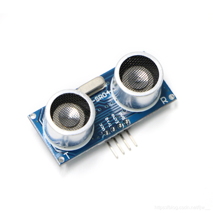
HC-SR04 module has four pins are: VCC GND Trig Echo
① VCC is connected to the 5V interface of the microcontroller.
② GND connected to the GND of the microcontroller.
③Using the IO port TRIG to trigger the ranging, to give a high-level signal of at least 10us, the module automatically sends eight square waves of 40khz, and automatically detects whether a signal returns.
④ When a signal returns, a high level is output through the IO port ECHO. The duration of the high level is the time from the transmission of the ultrasonic wave to the return. Test distance = (high level time * speed of sound (340M / S)) / 2.
Module use:
a control port sends a high level of more than 10us, you can wait for a high level output at the receiving port. The timer can be started as soon as there is an output. When the port becomes low level, the timer value can be read. At this time, it is the time of the ranging and the distance can be calculated.
The code part mainly uses the input of punctual atoms to capture the code changes.
Adopt the single chip PA6 pin to output 10us high level.
Use PB8 (TIM4_CH3) pin to calculate the time.
Input capture section:
#include "timer.h"
#include "usart.h"
#include "sys.h"

//定时器4通道3输入捕获配置

TIM_ICInitTypeDef  TIM4_ICInitStructure;

void TIM4_Cap_Init(u16 arr,u16 psc)
{
	GPIO_InitTypeDef GPIO_InitStructure;
	TIM_TimeBaseInitTypeDef  TIM_TimeBaseStructure;
 	NVIC_InitTypeDef NVIC_InitStructure;

	RCC_APB1PeriphClockCmd(RCC_APB1Periph_TIM4, ENABLE);	//使能TIM4时钟
 	RCC_APB2PeriphClockCmd(RCC_APB2Periph_GPIOB, ENABLE);  //使能GPIOB时钟

	GPIO_InitStructure.GPIO_Pin  = GPIO_Pin_8;  //PB8 清除之前设置
	GPIO_InitStructure.GPIO_Mode = GPIO_Mode_IPD; //PB8 输入
	GPIO_Init(GPIOB, &GPIO_InitStructure);
	GPIO_ResetBits(GPIOB,GPIO_Pin_8);						 //PB8 下拉

	//初始化定时器4 TIM4
	TIM_TimeBaseStructure.TIM_Period = arr; //设定计数器自动重装值
	TIM_TimeBaseStructure.TIM_Prescaler =psc; 	//预分频器
	TIM_TimeBaseStructure.TIM_ClockDivision = TIM_CKD_DIV1; //设置时钟分割:TDTS = Tck_tim
	TIM_TimeBaseStructure.TIM_CounterMode = TIM_CounterMode_Up;  //TIM向上计数模式
	TIM_TimeBaseInit(TIM4, &TIM_TimeBaseStructure); //根据TIM_TimeBaseInitStruct中指定的参数初始化TIMx的时间基数单位

	//初始化TIM2输入捕获参数
	TIM4_ICInitStructure.TIM_Channel = TIM_Channel_3;
  	TIM4_ICInitStructure.TIM_ICPolarity = TIM_ICPolarity_Rising;	//上升沿捕获
  	TIM4_ICInitStructure.TIM_ICSelection = TIM_ICSelection_DirectTI;
  	TIM4_ICInitStructure.TIM_ICPrescaler = TIM_ICPSC_DIV1;	 //配置输入分频,不分频
  	TIM4_ICInitStructure.TIM_ICFilter = 0x00;//IC1F=0000 配置输入滤波器 不滤波
  	TIM_ICInit(TIM4, &TIM4_ICInitStructure);

	//中断分组初始化
	NVIC_InitStructure.NVIC_IRQChannel = TIM4_IRQn;  //TIM4中断
	NVIC_InitStructure.NVIC_IRQChannelPreemptionPriority = 2;  //先占优先级2级
	NVIC_InitStructure.NVIC_IRQChannelSubPriority = 0;  //从优先级0级
	NVIC_InitStructure.NVIC_IRQChannelCmd = ENABLE; //IRQ通道被使能
	NVIC_Init(&NVIC_InitStructure);  //根据NVIC_InitStruct中指定的参数初始化外设NVIC寄存器

	TIM_ITConfig(TIM4,TIM_IT_Update|TIM_IT_CC3,ENABLE);//允许更新中断 ,允许CC1IE捕获中断

  TIM_Cmd(TIM4,ENABLE ); 	//使能定时器4

}


u8  TIM4CH3_CAPTURE_STA=0;	//输入捕获状态
u16	TIM4CH3_CAPTURE_VAL;	//输入捕获值

//定时器5中断服务程序
void TIM4_IRQHandler(void)
{

 	if((TIM4CH3_CAPTURE_STA&0X80)==0)//还未成功捕获
	{
		if (TIM_GetITStatus(TIM4, TIM_IT_Update) != RESET)

		{
			if(TIM4CH3_CAPTURE_STA&0X40)//已经捕获到高电平了
			{
				if((TIM4CH3_CAPTURE_STA&0X3F)==0X3F)//高电平太长了
				{
					TIM4CH3_CAPTURE_STA|=0X80;//标记成功捕获了一次
					TIM4CH3_CAPTURE_VAL=0XFFFF;
				}else TIM4CH3_CAPTURE_STA++;
			}
		}
	if (TIM_GetITStatus(TIM4, TIM_IT_CC3) != RESET)//捕获1发生捕获事件
		{
			if(TIM4CH3_CAPTURE_STA&0X40)		//捕获到一个下降沿
			{
				TIM4CH3_CAPTURE_STA|=0X80;		//标记成功捕获到一次上升沿
				TIM4CH3_CAPTURE_VAL=TIM_GetCapture3(TIM4);
		   		TIM_OC3PolarityConfig(TIM4,TIM_ICPolarity_Rising); //CC1P=0 设置为上升沿捕获
			}else  								//还未开始,第一次捕获上升沿
			{
				TIM4CH3_CAPTURE_STA=0;			//清空
				TIM4CH3_CAPTURE_VAL=0;
	 			TIM_SetCounter(TIM4,0);
				TIM4CH3_CAPTURE_STA|=0X40;		//标记捕获到了上升沿
		   		TIM_OC3PolarityConfig(TIM4,TIM_ICPolarity_Falling);		//CC1P=1 设置为下降沿捕获
			}
		}
 	}

    TIM_ClearITPendingBit(TIM4, TIM_IT_CC3|TIM_IT_Update); //清除中断标志位

}
Input capture .h file
#ifndef __TIMER_H
#define __TIMER_H
#include "sys.h"


void TIM4_Cap_Init(u16 arr,u16 psc);

#endif
GPIO PA6 output part:
#include "gpio.h"

void gpio_Init(void)
{

 GPIO_InitTypeDef  GPIO_InitStructure;

 RCC_APB2PeriphClockCmd(RCC_APB2Periph_GPIOA, ENABLE);	 //使能PA端口时钟

 GPIO_InitStructure.GPIO_Pin = GPIO_Pin_6;				 //LED0-->PA.6 端口配置
 GPIO_InitStructure.GPIO_Mode = GPIO_Mode_Out_PP; 		 //推挽输出
 GPIO_InitStructure.GPIO_Speed = GPIO_Speed_50MHz;		 //IO口速度为50MHz
 GPIO_Init(GPIOA, &GPIO_InitStructure);					 //根据设定参数初始化GPIOA.6


}
GPIO PA6 .h part
#ifndef __LED_H
#define __LED_H
#include "sys.h"


void gpio_Init(void);//初始化


#endif
main function:
#include "delay.h"
#include "usart.h"
#include "stm32f10x.h"
#include "timer.h"
#include "sys.h"
#include "gpio.h"

extern u8  TIM4CH3_CAPTURE_STA;		//输入捕获状态
extern u16	TIM4CH3_CAPTURE_VAL;	//输入捕获值
 int main(void)
 {

	float temp=0;
	NVIC_PriorityGroupConfig(NVIC_PriorityGroup_2);// 设置中断优先级分组2
	delay_init();	    	 //延时函数初始化
	uart_init(9600);	 			//9600
	gpio_Init();


 	TIM4_Cap_Init(0XFFFF,72-1);		//以1Mhz的频率计数
   	while(1)
	{


	 GPIO_SetBits(GPIOA,GPIO_Pin_6);						 //PA.6 输出高
	 delay_us(10);
	 GPIO_ResetBits(GPIOA,GPIO_Pin_6);						 //PA.6 输出低
 		delay_ms(10);

		if(TIM4CH3_CAPTURE_STA&0X80)//成功捕获到了一次高电平
		{
			temp=TIM4CH3_CAPTURE_STA&0X3F;
			temp*=65536;					//溢出时间总和
			temp+=TIM4CH3_CAPTURE_VAL;		//得到总的高电平时间
			temp=temp*170*0.0001;
			printf("distance:%f cm\r\n",temp);	//打印总的高点平时间
 			TIM4CH3_CAPTURE_STA=0;			//开启下一次捕获
 		}
		delay_ms(500);
	}
}
To achieve the effect:
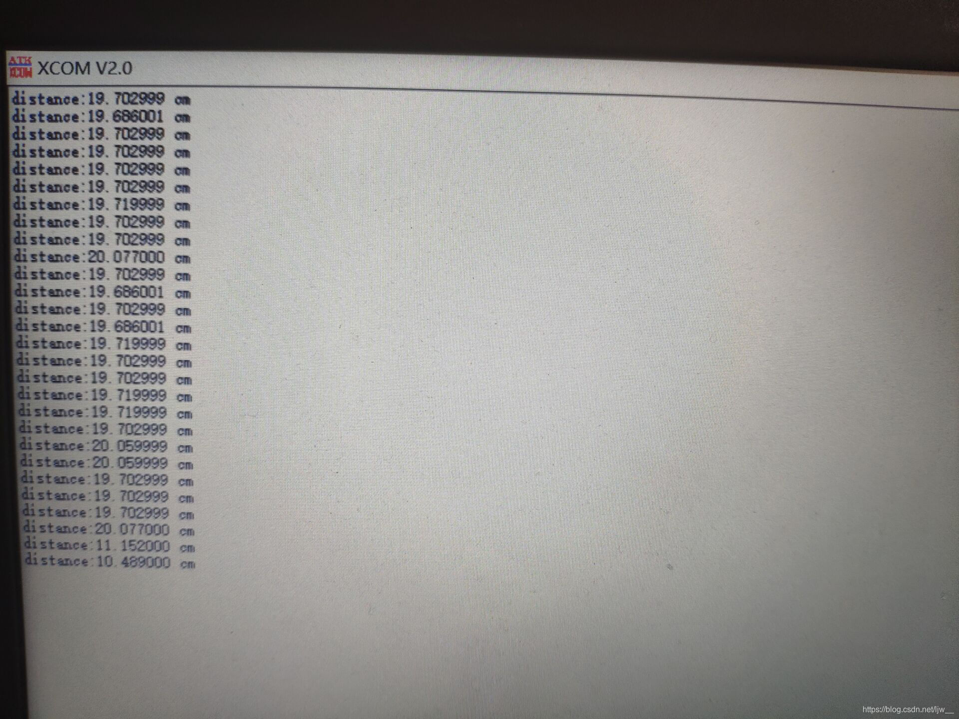
The last two lines of data only appeared when they were blocked by the hand
Code compression package: HC-SR04 code
