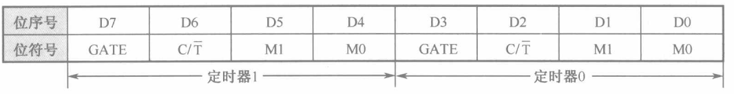
TMOD: Timer/Counter Working Mode Register

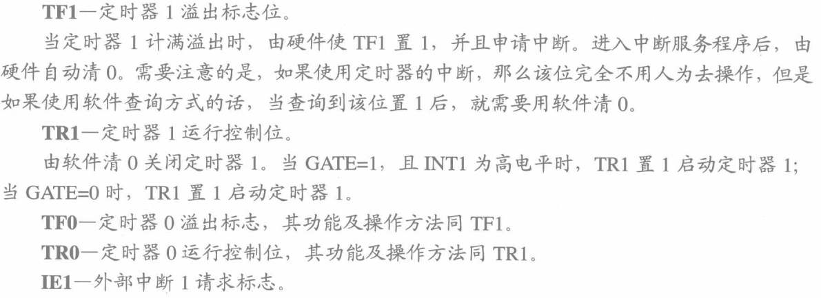
TCON: Timer/Counter Control Register


SCON: Serial port control register
The serial port control register SCON determines the working mode of serial port communication, controls the receiving and sending of data, and indicates the working status of the serial port, etc. The bit format is:

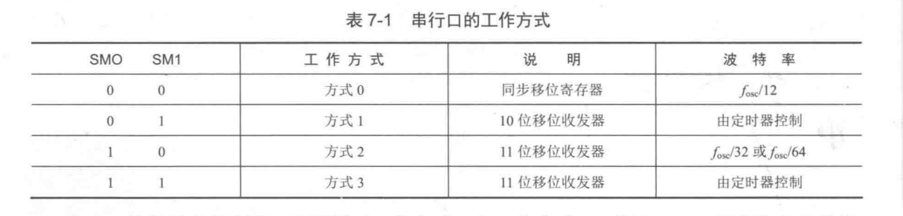
SMO, SM1 : serial port working mode control bits, corresponding to 4 working modes, as shown in Table 7-1 (fosc is the crystal oscillator frequency).
SM2:
The multi-machine communication control bit is mainly used for working mode 2 and working mode 3.
If SM2=1, multi-machine communication is allowed.
Multi-machine communication regulations: The 9th data bit is 1 (ie TB8=1), indicating that the data in this frame is an address frame: The 9th data bit is 0 (ie, TB8=0), then the data in this frame is a data frame.
When the 9th bit of data (in RB8) received by the slave is 1, the data is loaded into the receive buffer SBUF, and set RI=1 to apply for an interrupt to the CPU; if the 9th bit of data received (in RB8) ) Is 0, the interrupt flag RL is not set and the information is lost.
When SM2=0, regardless of whether the 9th bit of data received is 1, the interrupt flag RI is generated and the received data is loaded into SBUF. Multi-machine communication can be realized by applying this feature.
When the serial port works in mode 0, SM2 must be set to 0; when working in mode 1, if SM2=1, RI will be activated only when a valid stop bit is received.
REN : Allow to receive the control bit. When REN=1, reception is allowed; when REN=0, reception is prohibited. This bit is set or cleared by software.
TB8 : In mode 2 and mode 3, this bit is the ninth bit of sending data, and is used as a flag for sending address frames or data frames in multi-machine communication. TB8=1, it means that the sending frame is an address frame; TB8=0, it means that the sending frame is a data frame. In many communication protocols, it can be used as a parity bit. This bit is set or cleared by software. In mode 0 and mode 1, this bit is not used.
RB8 : The 9th bit of the received data. In Mode 2 and Mode 3, the 9th bit of data received is placed in RB8. It is either the agreed odd/even parity bit, or the agreed address/data flag bit. In mode 2 and mode 3 multi-machine communication, if SM2=1 and RB8=1, it means that the received data is an address frame.
TI : Transmit interrupt flag bit. Set when a frame of data is sent. TI=1, apply for an interrupt, indicating that the sending buffer SBUF is empty, and the CPU can send the next frame of data. After the interrupt is responded, TI cannot be cleared automatically, it must be cleared by software. ,
RI : Receive interrupt flag bit. After receiving a frame of valid data, it is set by hardware. RI=1. Apply for an interrupt, which means that one frame of data has been received and loaded into the receiving buffer SBUF. The CPU responds to the interrupt and takes the data. RI cannot be cleared automatically, it must be cleared by software.
The serial port transmit interrupt flag TI and receive interrupt flag RI are a total of one interrupt source. Therefore, after the CPU receives the interrupt request, it does not know whether to send the interrupt TI or receive the interrupt RI, and it must be judged by software. After the microcontroller is reset, the bits in the control register SCON are cleared.
PCON: Power control and baud rate selection register


Only one SMOD in the power control register PCON is related to the operation of the serial port.
SMOD: Baud rate multiplier bit. When the serial port works in mode 1, mode 2, and mode 3, if SMOD=1, the baud rate will be doubled;
if SMOD=0, the baud rate will not be doubled. When the microcontroller is reset, SMOD=0.
SBUF: serial data buffer
There are two buffer registers SBUF in the serial port, one is the sending register and the other is the receiving register, which are completely independent in physical structure. They are all byte-addressable registers, and the byte addresses are all 99H. This overlapping address is distinguished by read/write instructions: when serially sending, the CPU writes data to SBUF, at this time 99H means sending SBUF; when receiving serially, the CPU reads data from SBUF, at this time 99H means receiving SBUF.
SBUF refers to the two buffer registers in the serial port, one is the sending register and the other is the receiving register. They are completely independent in physical structure, but the addresses are overlapped. They are all byte-addressable registers, and the byte addresses are all 99H. As long as the two registers can be operated with different instructions when writing a program.
For example, SBUF=A ; this means that the data of A is moved into the sending register, and then the sending register sends the data out. A=SBUF ; means to assign the data in the accept register to A.