In the previous article, we explained the network peripheral part of STM32.
Articles include " STM32 Network Circuit Design ", " STM32 Network MAC Controller ", " STM32 Network DMA Controller ", and " STM32 Network Interruption ".
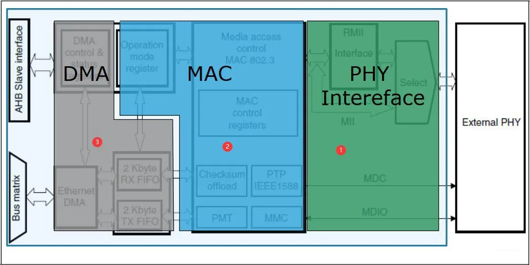
STM32 cannot carry on network communication when there is only network peripherals, because STM32 only provides SMI interface, MII and RMII interface. We also need to communicate with the external network chip, referred to as the PHY chip. The PHY models that I am familiar with are: RTL8201F, RTL8201E, RTL8201G, DP83848, YT8512C, etc. The original plan was to explain RTL8201F, but the content is too much, first take out the PHY register and talk about it.
Why does STM32 not integrate PHY?
PHY (PortPhysical Layer), Chinese can be called the port physical layer.
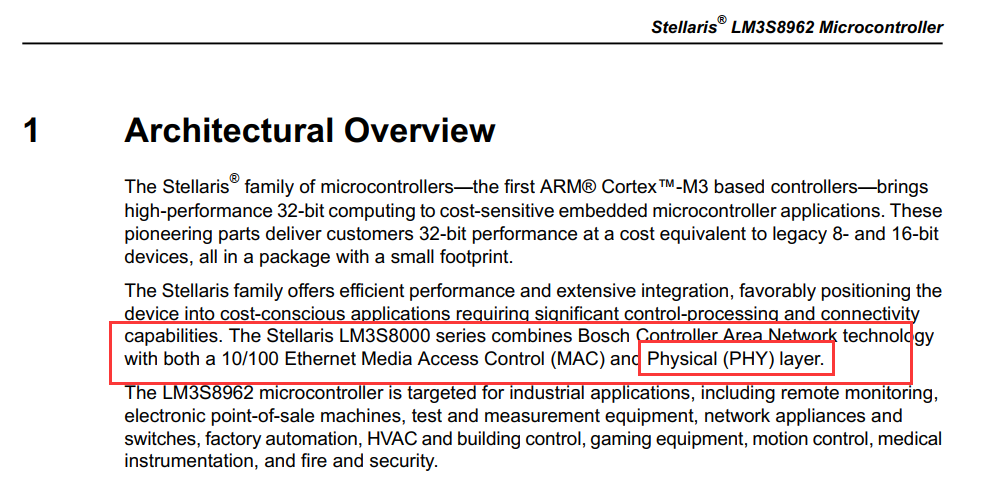
1. The PHY chip is an analog chip, which needs to convert the differential signal of the network cable into a digital signal. If integrated, the chip area will increase. If power consumption is to be reduced, a higher chip manufacturing process is required, which will directly increase the cost of the chip.
2. Not all STM32 users need to use the network, and the integration of PHY will increase the cost.
Therefore, STM32 does not integrate PHY not a technical problem, but the result of various considerations.
Is there no MCU with integrated PHY?
Yes, TI’s LM3S8962.
Let’s go back to the PHY registers. The external PHY chip registers are divided into 3 types
Basic: Basic register
Extended: extended register
Vendor-spcififc: Vendor special register
Among them, there are the following instructions in the 2012 version of the 802.3 protocol.
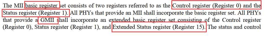
Different manuals have different descriptions of the basic registers. According to the description of the above figure of 802.3-2012, the basic registers are the controller register (register 0) and the status register (register 1). In the GMII (gigabit network) interface, the CNOOC extended status register (Register 15).
This article mainly explains the basic registers of PHY based on the 802.3-2012 protocol, not based on a specific chip.
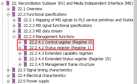
The position of register 0 and register 1 in the protocol document is as shown in the figure below
The 802.3-2012 protocol mentioned above can be downloaded from the ieee official website
Or download through Baidu network disk
Link: https://pan.baidu.com/s/1Nr_KHse32zysBKZ0btPceg
Extraction code: xhin
01. Control register (register 0)
Register 0 is the PHY control register, and the main working status of the PHY can be set through ControlRegister

bit15 Rset
When bit15 is 1, it means that the PHY is reset. Bit15 controls the PHY reset function. Write 1 in this position to reset the PHY. After reset, the other control and status registers of the port PHY will be restored to their default values. Each PHY reset should be completed within 0.5s. Bit15 remains at 1 during the reset process, and this bit should be automatically cleared after the reset is completed. Generally, when you want to change the working mode of the port (such as speed, duplex, flow control or negotiation information, etc.), after setting the register in the corresponding position, you need to reset the PHY through the Reset bit to make the configuration take effect.
Before the reset process is completed, there is no need for the PHY to accept write transactions to the control register, and before the reset process is completed, the write operations to bits other than bit15 in the control register may be invalid.
bit14 Loopback
Loopback is a commonly used function in debugging and fault diagnosis. After Bit14 is set to 1, the connection between PHY and external MDI will be disconnected logically, and sent from MAC via MII/GMII (maybe other MAC/PHY interfaces) The data will not be sent to the MDI, but looped back to the MII/GMII receiving channel of the port inside the PHY (usually in the PCS).
Through the Loopback function, you can check whether the MII/GMII and PHY interface parts are working properly, and can be used for fault location if the port is blocked. It should be noted that in many cases, the port may be Linkdown after the PHY sets Loopback, and the MAC cannot send frames to the port. At this time, you need to set the port ForceLink up to use the Loopback function.
bit13 Speed Selection(LSB)
Bit13 and Bit6 jointly realize the rate control function of the port. The specific corresponding relationship is shown in the figure below.

It should be noted that SpeedSelection only works when auto-negotiation is turned off. If auto-negotiation is set to the Enable state, this setting will not work;
In addition, to modify the settings of SpeedSelection, it is often necessary to reset the port for the configuration to take effect. Therefore, when setting this position, you need to check the auto-negotiation settings and reset the port through Bit15.
bit12 Auto-Negotiation Enable
Auto-negotiation (AN) switch. Set to 1 to turn on the AN function, and the working mode of the port is determined by auto-negotiation with the connection peer. If it is set to 0, the auto-negotiation function is disabled, and the working mode of the port is determined by the configuration in the corresponding position of the ControlRegister. It must be noted that for the 1000BASE-T interface, auto-negotiation must be turned on.
bit11 Power Down
Port working switch: set to 1 to make the port enter the PowerDown (low power consumption state) mode. Under normal circumstances, the PHY will not send data to the MII and MDI in the PowerDown mode. The PowerDown mode is generally used when the software shuts down the port. It should be noted that the port is restored from PowerDown mode, and the port needs to be reset to ensure reliable connection of the port.
bit10 Isolate
Isolation status switch: Changing the position to 1 will cause the PHY and MII interface to be in electrical isolation. Except for the signal of the MDC/MDIO interface, the other MII pins are in a high impedance state. IEEE802.3 does not regulate the state of the MDI interface during Isolate, and the MDI terminal may still be running normally at this time. Isolate is not used in actual applications. And, it’s worth noting that, as the mainstream MAC interfaces of many 100M PHY chips are SMII/S3MII, the interfaces of 8 ports are interrelated, and setting Isolate on one port may affect the normal use of other ports, so Be careful not to change the status of bit10 arbitrarily during use.
bit9 Restart Auto-Negotiation
Restart the auto-negotiation switch: Setting Bit9 to 1 will restart the auto-negotiation process of the port, of course, the premise is that Auto-NegotiationEnable is enabled. Generally, after the auto-negotiation capability information of the port is modified, the auto-negotiation is restarted by setting Bit9 to 1, so that the port establishes a link according to the new configuration.
bit8 Duplex Mode
Duplex mode setting: Bit8 is set to 1 and the port is set to full duplex, and when it is set to 0, the end is set to half duplex. The setting of DuplexMode is the same as the setting of SpeedSelection. The setting of DuplexMode only works when auto-negotiation is turned off. If auto-negotiation is set In the Enable state, this setting has no effect, and the duplex mode of the port is determined according to the AN result. The modified configuration of DuplexMode also needs to reset the port to take effect.
bit7 Collision Test
Collision signal (COL) test switch: When the COL signal needs to be tested, Bit7 can be set to 1, then the PHY will output a COL pulse for testing. In the actual test operation, the port can also be configured in a half-duplex state, and the COL signal can be tested by sending frame conflicts, so this configuration is of little practical value.
bit6 Speed Selection(MSB)
Together with Bit13, it can realize the rate control function of the port.
bit5 Unidirectional enable
When the 12th bit is 1 or the 8th bit is 0, this bit is ignored.
When the 12th bit is 0 and the 8th bit is 1:
1: Enable transmission from the MII interface, regardless of whether the PHY determines that a valid link has been established
0: Only when the PHY determines that a valid link has been established, the transmission from the MII interface is enabled
Bits 4:0 reserved
Reserved bits, they should be written as zeros and should be ignored when read; however, the PHY should return the value zero in these bits.
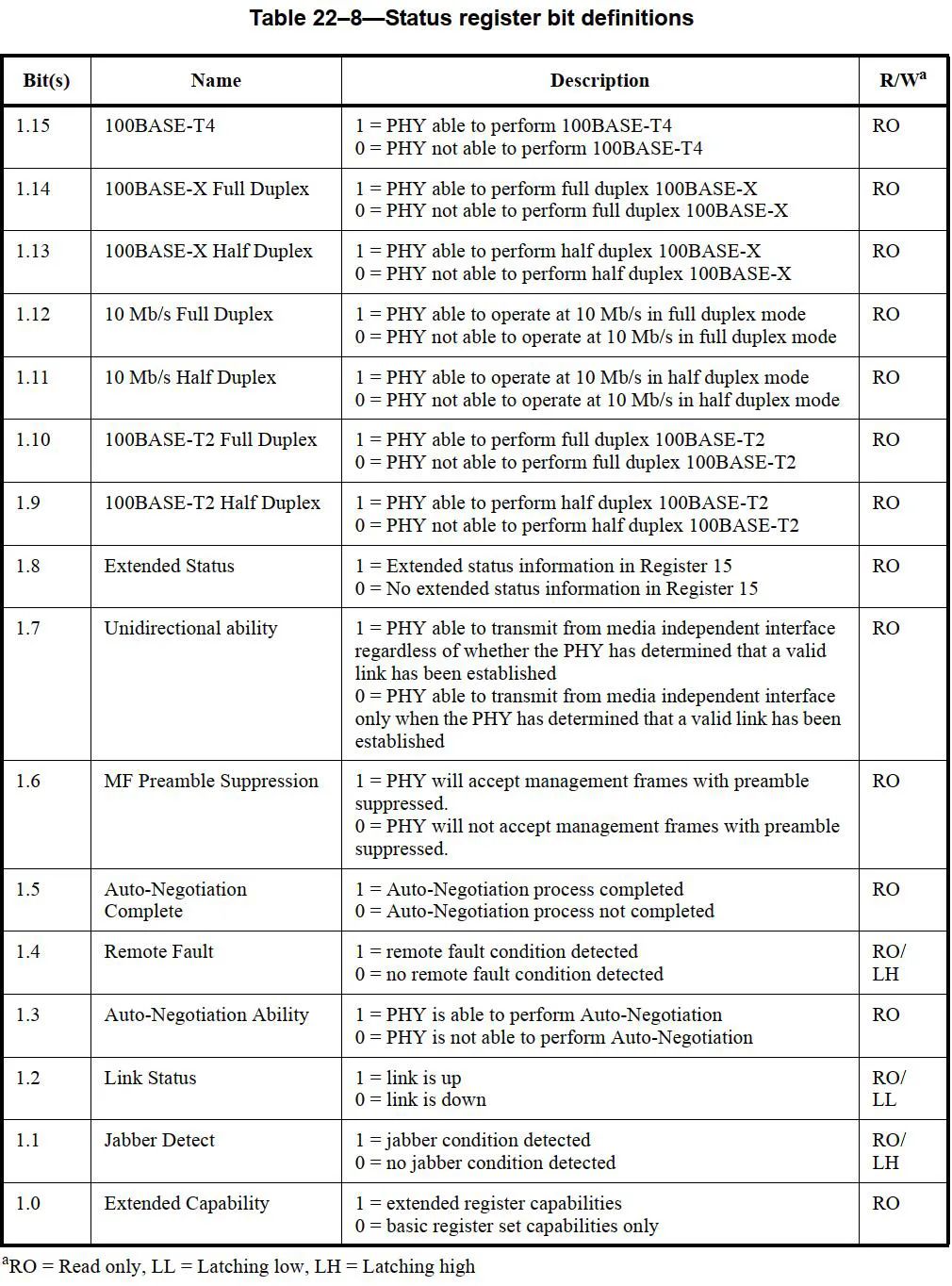
02. Status register (register 1)
Register 1 is the PHY status register, which mainly contains the status information of the PHY.
bit15 100BASE-T4
The PHY uses the 100BASE-T4 signaling specification to perform link transmission and reception capabilities. 1: Ability; 0: No ability.
bit14 100BASE-X Full Duplex
The PHY uses the 100BASE-X signaling specification to perform full-duplex link transmission and reception capabilities. 1: Ability; 0: No ability.
bit13 100BASE-X Half Duplex
The PHY uses the 100BASE-X signaling specification to perform half-duplex link transmission and reception capabilities. 1: Ability; 0: No ability.
bit12 10Mb/s Full Duplex
PHY has the ability to perform full-duplex link transmission and reception when running at a speed of 10Mb/s. 1: Ability; 0: No ability.
bit11 10Mb/s Half Duplex
PHY has the ability to perform half-duplex link transmission and reception when running at a speed of 10Mb/s. 1: Ability; 0: No ability.
bit10 100BASE-T2 Full Duplex
PHY has the ability to perform full-duplex link transmission and reception using the 100BASE-T2 signaling specification. 1: Ability; 0: No ability.
bit9 100BASE-T2 Half Duplex
PHY has the ability to perform half-duplex link transmission and reception using the 100BASE-T2 signaling specification. 1: Ability; 0: No ability.
bit8 Externded Status
1: Enable register 15
0: Disable register 15
bit7 Unidirectional ability
1: The PHY has the ability to encode and transmit data from the PHY through the MII interface, regardless of whether the PHY has determined that a valid link has been established.
0: Only when the PHY determines that a valid link has been established, the transmission from the MII interface is enabled
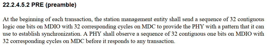
bit6 MF Preamble Suppression
1: PHY can accept management frames regardless of whether there is a preamble pattern in front of them.
0: PHY cannot accept management frames unless there is a preamble pattern in front of them.
Preamble mode.
It is described in 22.2.4.5.2 in the official document. You can check it yourself.
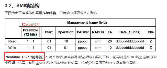
In fact, we also explained this preamble before. In the article "SMI Interface of STM32 Network" as shown below, it is recommended that students who have not read this article read it.
bit5 Auto-Negotiation Complete
AN completion status indicator bit: Bit5 indicates the status bit indicating whether the port AN process is completed. In the case of ANEnable, Bit5=1 indicates that the auto-negotiation process has successfully ended. At this time, the other registers of the PHY related to the Link status are correct and reliable. If the AN process is not completed, the status information may be wrong. During debugging and abnormal fault handling, the status of this bit register can be used to judge whether the AN is successful, so as to further check whether the AN-related settings are correct, or whether the AN function of the chip is normal.
bit4 Remote Fault
Remote error indication bit: Bit4=1 means that the link partner (LinkPartner) has an error. As for the specific type of error and the error detection mechanism, it is not defined in the specification. It is free to play by the manufacturer of the PHY, and the general manufacturer will use other registers. (Register16-31 is defined by the manufacturer) Indicate more detailed error types. In the port-related fault verification, RemoteFault is an important indication information. The RemoteFault information of the interconnected parties (other specific error indications may be added) can help locate the cause of the fault.
bit3 Auto-Negotiation Ability
1: PHY enables auto-negotiation
0: PHY does not enable auto-negotiation
bit2 Link Status
Link status indicator bit: Bit2=1 means port Linkup, 0 means port Linkdown. In practical applications, Bit2 is generally used to determine the status of the port. Moreover, the general MAC chip also polls this register value of the PHY to determine the link status of the port (this process may have different names, for example, BCM is called LinkScan, and Marvell is called PHYPolling.) As mentioned earlier, in ANEnable In this case, the LinkStatus information is correct and reliable only when Auto-NegotiationComplete indicates that it has been completed, otherwise there may be errors.
bit1 Jabber Detect
1 : The jitter (poking) state is detected
0: No jitter (poking) state detected
bit0 Extended Capability
1: PHY provides an extended function set, which can be accessed through an extended register set.
0: No extension register is provided.
03, register 15
Register 15 main mode Gigabit network mode, the status of the PHY.
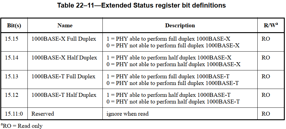
As shown in the figure above, register 15 mainly describes the status of PHY in Gigabit network mode. The specific meaning is similar to the relevant bits of register 1.
bit15 1000BASE-X Full Duplex
The PHY uses the 1000BASE-X signaling specification to perform full-duplex link transmission and reception capabilities. 1: Ability; 0: No ability.
bit14 1000BASE-X Half Duplex
The PHY uses the 100B0ASE-X signaling specification to perform half-duplex link transmission and reception capabilities. 1: Ability; 0: No ability.
bit13 1000BASE-T Full Duplex
PHY has the ability to perform full-duplex link transmission and reception using the 1000BASE-T signaling specification. 1: Ability; 0: No ability.
bit12 1000BASE-T Half Duplex
PHY has the ability to perform half-duplex link transmission and reception using the 1000BASE-T signaling specification. 1: Ability; 0: No ability.
Bits 11:0 reserved
Reserved bit, ignored when reading.
04
Other registers
In addition to the basic registers, the 802.3-2012 protocol also mentions other registers. Here is a brief explanation, without focusing on them.
Register 2 , 3 : Chip ID register
Registers 2 and 3 are respectively PHYID registers. Known from the kernel code, register 2 (PHYID1) is the upper 16 bits, and register 3 (PHYID2) is the lower 16 bits. They are used as the identification of PHY chips and are generally considered to have little effect. In the past, the same main CPU was used with different PHY combinations and different boards, and the same core was used. Here, PHYID can be used to make the distinction.
Register 4 : Auto-negotiation notice register
This register holds the characteristics and capabilities of the PHY itself. For example, PHY supports flow control, 100M full duplex/half duplex, 10M full duplex/half duplex, etc.
When it is set to enable auto-negotiation to be advertised on MDI through FLP. If it is not enabled, the configuration of this register is invalid.
Register 5 : Auto-negotiation peer capability notification register
This register is similar to register 4, and it represents the characteristics and capabilities of the opposite end (switch or PC). Also note that this register information is only valid when auto-negotiation is enabled. Since this register represents the status of the opposite end, the value of the register is generally designed to be read-only, but some chips such as the flow control bit 5.10FCS of dm9000 are readable and writable.
This register is mainly used to understand the situation of the opposite end. When a problem occurs, you can understand the information of the opposite end to roughly locate the range. Instead of blindly looking for your own reasons. In the unlikely event that the switch at the opposite end fails, this register is a strong field evidence.
Click to view the album where this article is located, STM32F207 network development
Pay attention to the official account, and receive article updates as soon as possible .