MCU overview
- What is a microcontroller
Single-chip (Single-Chip-Microcomputer) is also called single-chip microcomputer.
Its structural feature is that the basic functional components of the computer are all integrated on a semiconductor chip.
- Characteristics of single chip microcomputer
- High integration, small size, strong anti-interference ability and high reliability.
- The development performance is good, the development cycle is short, and the control function is strong.
- Low power consumption, low voltage, power-off protection function, widely used in various intelligent instruments.
- Good versatility and flexibility.
- Has a good performance-price ratio.
- Application fields of single chip microcomputer
- Industrial automation control.
- Intelligent instrumentation.
- communication device.
- Automotive electronics and aerospace electronic systems.
- Household appliances.
- Development trend of single chip microcomputer
- High integration.
- high performance.
- Low power consumption.
- High cost performance.
Structure and principle of MSC-51 single chip microcomputer
- The internal structure of the MSC-51 MCU The internal
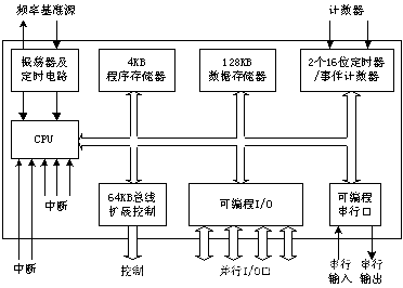
resources of the 80C51 MCU mainly include:
· 1 8-bit central processing unit (CPU);
· 1 internal oscillator and clock circuit;
· 4KB on-chip program memory (ROM);
· 256 words Section of on-chip RAM;
· 2 16-bit timers / timers;
· Control circuit addressable 64KB external program memory and 64KB data storage space;
· 4 8-bit bidirectional I / O ports;
· 1 full dual Industrial serial port;
· 5 interrupt sources. - The CPU can be divided into two parts, the arithmetic unit and the controller.
2.1 Controller
(1) Program Counter PC (Program Counter)
16-bit special register, which stores the first address of the next instruction to be executed, that is, the content of the PC determines the program Running track. When the CPU wants to fetch the instruction, the content of the PC will appear on the address bus; after the instruction is fetched, the content of the PC can be automatically increased by 1 to ensure the sequential execution of the program.
After the system is reset, the content of the PC will be automatically assigned to 0000H, which means that the CPU will start the instruction at the address 0000H of the program memory after reset.
(2) Instruction register IR (Instruction Register) is
an 8-bit register used to temporarily store instructions to be executed, waiting for decoding.
(3) Instruction Decoder ID (Instruction Decoder)
(4) Data Pointer DPTR (Data Pointer)
DATR can be used to store the address of the internal ROM, and can also be used to store the addresses of off-chip RAM and off-chip ROM.
2.2 Operator
(1) ACC (Accumulator)
(2) ALU (Arithmetic Logic Unit)
(3) PSW (Program State Word) - MCS-51 external pins and functions
51 single-chip microcomputers using the HMOS manufacturing process generally use a 40-pin dual in-line package (DIP).
Using the CHMOS manufacturing process 51 single chip microcomputer can also use 44 pins square package. - Memory division method
4.1 Storage structure
Princeton structure: instruction memory and program storage are merged together.
Harvard structure: instruction memory and data memory are set separately.
4.2 Division of storage space
Physical address: 4 storage spaces. That is, on-chip ROM, off-chip ROM, on-chip RAM, off-chip RAM.
Logical address: Because the on-chip and off-chip program memories are uniformly addressed, there are only three storage spaces logically, namely program memory, on-chip data memory, and off-chip data memory. - SCM reset in
two ways: power-on reset and key reset. - MCU clock
Clock cycle: The crystal oscillator or external oscillation cycle becomes the clock cycle, also known as the beat.
State cycle: equal to 2 clock cycles.
Machine cycle: equal to 6 state cycles, 12 clock cycles.
Instruction cycle: equal to 1 ~ 4 and its cycle. - I / O ports
P0 ~ P3 can be provided to users as quasi-bidirectional general-purpose I / O ports. Among them, only P0 needs to be connected with an external pull-up resistor; when the off-chip memory needs to be expanded, P2 is used as the other address first interface, and P0 is Other address line / data line multiplexing interface, at this time it is a real bidirectional port. The P3 port uses the second output function.
