Contents
Chapter 1 Introduction 1
Chapter 2 Classification and status quo of mobile robot path planning methods 5
2.1 Case-based learning planning method 5
2.2 Environment model-based planning method 6
2.3 Behavior-based structure 7
Chapter 3 Robot mouse design tasks and Scheme Analysis 10
3.1 Introduction to Micro Robot Mouse Competition 10
3.2 Design Task Decomposition 11
3.3 Robot Mouse Task Analysis and Behavior-Based Design 12
3.3.1 Inspection Channel, Walking Behavior Along the Wall 13
3.3.2 Judging Channel, Triggering Rotation Behavior 19
3.3 Mechanical Platform 21
3.4.1 Selection of mobile mechanism scheme of robot mouse 21
3.4.2 Installation and selection of wheels 26
3.4.3 Selection of wheels 27
3.5 Cooperative use of multiple sensors 28
3.5.1 Sensor application in robotics 28
3.5.2 Infrared sensor of robot mouse 30
3.5.3 Robot mouse sensor design scheme 34
Chapter 4 Robot mouse four-phase stepping motor and drive circuit design 38
4.1 Overview of stepping motor control 38
4.2 Structure and working principle of reactive stepping motor 39
4.3 Determination of stepping motor power 43
4.4 Driving power supply 45
4.4.1 Control of stepping motor 47
4.4.2 Driving circuit of stepping motor used in robot mouse 49
4.5 Single-chip microcomputer control 53
4.6 SCM control program flow chart 64
Chapter 5 Mechanical design of a practical autonomous vacuuming robot based on the robot mouse control system 69
5.1 Kinematic analysis of differential car
body 70 5.2 Drive wheel mechanism composition 74
5.3 Follower wheel mechanism composition 79
Conclusion 81
Acknowledgments 83
Reference 85
Research on Autonomous Small Robotic Mouse System Based on Behavioral Design
Abstract
Mobile robot is a comprehensive subject developed in recent years, which integrates the latest research results of mechanics, electronics, computer, automatic control and artificial intelligence. Represents the highest achievement of mechatronics. Mobile robots are commonly used in industrial production to complete tasks such as transportation and loading and unloading, and are also widely used in different industries such as agriculture and medical care.
In the research of mobile robot-related technologies, path planning technology is an important research field [17]. This paper first discusses and summarizes the main path planning techniques at present. This paper comprehensively and systematically summarizes the research status of mobile robot path planning technology from three aspects: case-based, environment model-based and behavior-based.
The behavior-based method was established by Brooks of MIT in his famous inclusive structure [42]. It is a technology inspired by biological systems to design autonomous robots, and it is also the focus of this paper. . It uses a bottom-up principle system similar to animal evolution, trying to build a complex system from a simple agent. It is a new development trend to use it to solve the path planning problem of mobile robots. It decomposes the navigation problem into many relatively independent behavioral units, such as tracking, collision avoidance, and target guidance. These behavioral units are some complete motion control units composed of sensors and actuators, with corresponding navigation functions. The behavioral modes adopted by each behavioral unit are different, and these units complete the navigation task by coordinating with each other.
Behavior-based robotics is opposed to abstract definitions, so a concrete explanation is more suitable for the philosophical thinking of this field. The important research content of behavior-based robotics is system structure rather than algorithm. The performance of behavior-based robots in unstructured dynamic environments is very superior. Similar robots designed with symbol-based robotics cannot achieve the following performance: a
. High speed, high flexibility. The movement speed in the dynamic and complex environment is very fast;
b. High robustness. Can withstand local damage;
c. High efficiency. The software code can be one hundredth of the traditional one, and the hardware can be one tenth of the traditional one;
d. Economy. The price is one tenth of the traditional one;
e. Scalability. Performance can be increased with few changes to the original system;
f. Reliability. Distributed self-organized parallel work, strong reliability.
In order to further study the behavior-based planning method, a real environment and task model is introduced, that is, the miniature robot mouse competition held by IEEE every year, and the feasibility of the algorithm is demonstrated by designing a behavior-based robot mouse model. This competition requires the robot to be able to autonomously complete the task of traversing the maze in an unknown environment. Aiming at the unknown or uncertain environment model of the robot mouse competition, as well as some limitations of the robot itself, a behavior-based research method was used to realize the automatic obstacle avoidance of a self-designed autonomous small mobile robot in an unknown and dynamic environment. By modeling the environment in which the robot mouse operates, the behavior-based method is used to decompose and construct the robot mouse's task execution, walking along the wall, and judging obstacle rotation, and theoretically analyze the sensor layout and mechanical platform design of the robot mouse.
The model studied in this paper is a self-built robotic mouse physical platform, which is driven by two stepping motors, and its appearance is shown in Figure 1. There are three diffuse reflection infrared photoelectric sensors in the forward and side directions of the robot mouse, with a distance of 10cm to 20cm, and two collision switches. The location of the sensors is shown in Figure 2. When there is an obstacle in front of the sensor, the output of the sensor is 1, otherwise 0.
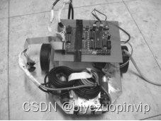
Figure 1 The appearance photo of the robot mouse
is controlled by the AT89S52 single-chip microcomputer of ATMEL company, the small four-phase stepping motor and the dedicated PMM8713 stepping motor drive scheme, the infrared proximity switch is used as the main sensor, and the differential chassis structure is initially realized for the miniature robot mouse. The design of the robotic mouse for the competition.
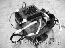
Figure 2 Sensor layout
of the robot mouse The design of the behavior is closely related to the robot's ability. The hardware of the robot limits the ability of certain behaviors of the robot. According to the game tasks of the robot mouse, the behavior of the robot mouse is decomposed as shown in Figure 3.
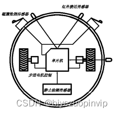
Figure 3 The basic behavioral components of the robot mouse
The design of the robot mouse is a verification design of the behavior-based planning method, which is widely used in household service robots, the most typical example is the autonomous vacuuming robot. Based on the sensing and control system of the robot mouse, this paper further proposes a mechanical chassis design scheme for the autonomous vacuuming robot, which improves the practical significance of the robot mouse.
Keywords: mobile robot; path planning; single-chip microcomputer control stepper motor drive; infrared proximity switch sensor; autonomous vacuuming robot
#include<reg52.h>
#define uint unsigned int
#define uchar unsigned char
uint time0,time1,i;
sbit p10=P1^0;
sbit p11=P1^1;
sbit p12=P1^2;
sbit p13=P1^3;
sbit int00=P3^2;
sbit int11=P3^3;
sbit p20=P2^0;
sbit p21=P2^1;
void delay(int x)			     //延时
{


  uint i;
  for(i=0;i<x;i++)
  {

    }
}
void turn90(void)				 //转90度
{


 p13=!p13;
	   for(i=0;i<500;i++)
	   {


	    p10=!p10;
	    p12=!p12;
	    delay(300);
		}
 p13=!p13;
}
void exchang_1(void) interrupt 0 //沿墙传感器
{


 uint i,w;
 delay(10);
 w=int00;
 EA=0;
 	if(w==0)
	{


    i=time0;
    time0=time1;
    time1=i;
	}
 EA=1;
}
void front(void) interrupt 2    //前方传感器1,2
{


    uint m,n;
    m=p20;
    n=p21;
    EA=0;
    delay(10);
	  while(m==0&&n==1)
      {


	   n=p21;
	   m=p20;
	   p12=!p12;
	   delay(300);
	  }
	  while(m==1&&n==0)
      {


	   n=p21;
	   m=p20;
	   p10=!p10;
	   delay(300);
	  }
	  if(m==0&&n==0)
      {


	   n=p21;
	   m=p20;
	   turn90();
	   EA=1;
	   }
    EA=1;
}


