clase vtkCutter
vtkCutterSe puede usar el corte usando una función implícita especificada por el usuario vtkDataSet.
vtkCutterEs un filtro que puede usar cualquier subclase de vtkImplicitFunction para segmentar datos. Es decir, se crea una superficie poligonal correspondiente a la función implícita F(x,y,z) = valor(es) donde se pueden especificar uno o más valores para el corte.
En VTK, cortar significa Nreducir una unidad de tamaño a N-1una superficie cortada de tamaño . vtkPlanePor ejemplo, un tetraedro genera triángulos cuando es cortado por un plano (es decir, función implícita). (El recorte, por el contrario, toma celdas N-dimensionales y crea primitivas N-dimensionales).
vtkCutterNormalmente se usa para "cortar" un conjunto de datos, produciendo superficies que se pueden visualizar. También puede usar vtkCutter para la representación de volumen. vtkCutter hace esto generando múltiples superficies de corte (generalmente planas) ordenadas (y renderizadas) de atrás hacia adelante. Establece la superficie para que sea translúcida para dar un efecto de representación volumétrica.
Tenga en cuenta que los datos se pueden dividir utilizando 1) un valor escalar asociado con un conjunto de datos o 2) una función implícita asociada con esta clase. De manera predeterminada, la función implícita se usa para recortar el conjunto de datos si está establecida; de lo contrario, se usa el escalar del conjunto de datos para realizar el recorte.
interfaz
Número máximo de contornos
Utilice el método SetNumberOfContourspara establecer el límite superior del número de contornos; el método GetNumberOfContourspara obtener el límite superior del número de contornos;
sin embargo, al configurar , si SetValuese excede SetNumberOfContoursel límite superior establecido , el valor del límite superior aumentará automáticamente;
void SetNumberOfContours(int number) {

     this->ContourValues->SetNumberOfContours(number); }
vtkIdType GetNumberOfContours() {

     return this->ContourValues->GetNumberOfContours(); }
El contorno corresponde al valor del paso
Utilice el método SetValuepara establecer iel paso correspondiente al contorno o las coordenadas en la dirección normal de la función implícita.
void SetValue(int i, double value) {

     this->ContourValues->SetValue(i, value); }
double GetValue(int i) {

     return this->ContourValues->GetValue(i); }
double* GetValues() {

     return this->ContourValues->GetValues(); }
void GetValues(double* contourValues) {

     this->ContourValues->GetValues(contourValues); }
Ejemplo:
al establecer la posición del primer contorno en 0,99:
cutter->SetValue(0, 0.99);
Aparece un contorno en la parte inferior de la imagen visible,

establezca 5 contornos seguidos con un intervalo de 20 horas;
cutter->SetNumberOfContours(5);
for (size_t i = 0; i < 5; i++) {


    cutter->SetValue(i, 0.99 + 20 * i);
}
cinco contornos que aparecen en la parte inferior de la imagen visible;
GenerarValores
El método de uso GenerateValuespuede establecer el número límite superior de contornos y el valor de paso correspondiente de los contornos.La función es generar varios contornos dentro del rango y generar un contorno dentro del rango desde el valor mínimo minhasta el valor máximo .maxnumContours
void GenerateValues(int numContours, double range[2]) {


     this->ContourValues->GenerateValues(numContours, range);
}
void GenerateValues(int numContours, double rangeStart, double rangeEnd) {


     this->ContourValues->GenerateValues(numContours, rangeStart, rangeEnd);
}
Establecer 5 contornos de forma continua con un intervalo de 20 horas;
cutter->GenerateValues(5, .99, .99 * 20 * 5);
El efecto es el mismo que usarlo 5 veces seguidas SetValue.
establecer función implícita
Establezca la función implícita utilizada para generar el contorno de corte, que se hereda de vtkImplicitFunctionla subclase de la clase, se usa comúnmente vtkPlanepara el corte plano;
virtual void SetCutFunction(vtkImplicitFunction*);
vtkGetObjectMacro(CutFunction, vtkImplicitFunction);
logo
Si esta bandera está habilitada, el valor escalar de salida se interpolará a partir del valor de la función implícita, en lugar de a partir de los datos escalares de entrada.
vtkSetMacro(GenerateCutScalars, vtkTypeBool);
vtkGetMacro(GenerateCutScalars, vtkTypeBool);
vtkBooleanMacro(GenerateCutScalars, vtkTypeBool);
Si esta opción está habilitada GenerateTriangles(activada de forma predeterminada), la salida serán triángulos; de lo contrario, la salida serán polígonos que se intersecan. para calcular aguas abajo.
vtkSetMacro(GenerateTriangles, vtkTypeBool);
vtkGetMacro(GenerateTriangles, vtkTypeBool);
vtkBooleanMacro(GenerateTriangles, vtkTypeBool);
Precisión de salida
vtkSetClampMacro(OutputPointsPrecision, int, SINGLE_PRECISION, DEFAULT_PRECISION);
vtkGetMacro(OutputPointsPrecision, int);
Aviso
vtkCutterLa salida vtkPolyDataes la misma que la normal vtkPolyData, el resultado de un contorno es el mismo que el resultado que contiene varios contornos y los resultados de la topología interna están dispersos. El orden de puntos y puntos también es disperso.Si desea obtener una curva de nivel por separado, lo mejor es generar solo una curva de nivel, para que el resultado sea fácil de procesar;
ejemplo oficial
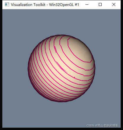
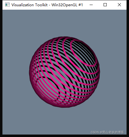
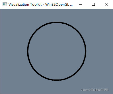
Cortar el contorno de la pelota.
vtkNew<vtkNamedColors> colors;

vtkSmartPointer<vtkPolyData> inputPolyData;
vtkNew<vtkSphereSource> sphereSource;
sphereSource->SetThetaResolution(30);
sphereSource->SetPhiResolution(15);
sphereSource->Update();
inputPolyData = sphereSource->GetOutput();

vtkNew<vtkPolyDataMapper> inputMapper;
inputMapper->SetInputData(inputPolyData);

// Create a plane to cut
vtkNew<vtkPlane> plane;
plane->SetOrigin(inputPolyData->GetCenter());
plane->SetNormal(1, 1, 1);

double minBound[3];
minBound[0] = inputPolyData->GetBounds()[0];
minBound[1] = inputPolyData->GetBounds()[2];
minBound[2] = inputPolyData->GetBounds()[4];

double maxBound[3];
maxBound[0] = inputPolyData->GetBounds()[1];
maxBound[1] = inputPolyData->GetBounds()[3];
maxBound[2] = inputPolyData->GetBounds()[5];

double center[3];
center[0] = inputPolyData->GetCenter()[0];
center[1] = inputPolyData->GetCenter()[1];
center[2] = inputPolyData->GetCenter()[2];

double distanceMin = sqrt(vtkMath::Distance2BetweenPoints(minBound, center));
double distanceMax = sqrt(vtkMath::Distance2BetweenPoints(maxBound, center));

// Create cutter
vtkNew<vtkCutter> cutter;
cutter->SetCutFunction(plane);
cutter->SetInputData(inputPolyData);
cutter->GenerateValues(20, -distanceMin, distanceMax);

vtkNew<vtkPolyDataMapper> cutterMapper;
cutterMapper->SetInputConnection(cutter->GetOutputPort());
cutterMapper->ScalarVisibilityOff();

// Create plane actor
vtkNew<vtkActor> planeActor;
planeActor->GetProperty()->SetColor(colors->GetColor3d("Deep_pink").GetData());
planeActor->GetProperty()->SetLineWidth(5);
planeActor->SetMapper(cutterMapper);

// Create input actor
vtkNew<vtkActor> inputActor;
inputActor->GetProperty()->SetColor(colors->GetColor3d("Bisque").GetData());
inputActor->SetMapper(inputMapper);

// Create renderers and add actors of plane and cube
vtkNew<vtkRenderer> renderer;
renderer->AddActor(planeActor); // display the rectangle resulting from the cut
renderer->AddActor(inputActor); // display the cube

// Add renderer to renderwindow and render
vtkNew<vtkRenderWindow> renderWindow;
renderWindow->AddRenderer(renderer);
renderWindow->SetWindowName("ContoursFromPolyData");
renderWindow->SetSize(600, 600);

vtkNew<vtkRenderWindowInteractor> interactor;
interactor->SetRenderWindow(renderWindow);
renderer->SetBackground(colors->GetColor3d("Slate_grey").GetData());
renderWindow->Render();
interactor->Initialize();
interactor->Start();
La imagen de la izquierda muestra el contorno y la esfera original al mismo tiempo, la imagen de la derecha muestra vtkCuttersolo el contorno generado;
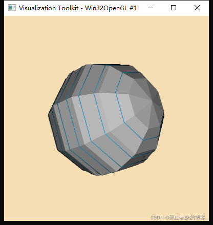
Salida de punto de curva de contorno de esfera cortada
vtkNew<vtkNamedColors> colors;
vtkColor3d lineColor = colors->GetColor3d("peacock");
vtkColor3d modelColor = colors->GetColor3d("silver");
vtkColor3d backgroundColor = colors->GetColor3d("wheat");
vtkNew<vtkSphereSource> modelSource;
vtkNew<vtkPlane> plane;
vtkNew<vtkCutter> cutter;
cutter->SetInputConnection(modelSource->GetOutputPort());
cutter->SetCutFunction(plane);
cutter->GenerateValues(10, -0.5, 0.5);
vtkNew<vtkPolyDataMapper> modelMapper;
modelMapper->SetInputConnection(modelSource->GetOutputPort());
vtkNew<vtkActor> model;
model->SetMapper(modelMapper);
model->GetProperty()->SetDiffuseColor(modelColor.GetData());
model->GetProperty()->SetInterpolationToFlat();
vtkNew<vtkStripper> stripper;
stripper->SetInputConnection(cutter->GetOutputPort());
stripper->JoinContiguousSegmentsOn();
vtkNew<vtkPolyDataMapper> linesMapper;
linesMapper->SetInputConnection(stripper->GetOutputPort());
vtkNew<vtkActor> lines;
lines->SetMapper(linesMapper);
lines->GetProperty()->SetDiffuseColor(lineColor.GetData());
lines->GetProperty()->SetLineWidth(3.0);
vtkNew<vtkRenderer> renderer;
vtkNew<vtkRenderWindow> renderWindow;
renderWindow->AddRenderer(renderer);
renderWindow->SetSize(640, 480);
renderWindow->SetWindowName("ExtractPolyLinesFromPolyData");
vtkNew<vtkRenderWindowInteractor> interactor;
interactor->SetRenderWindow(renderWindow);
// Add the actors to the renderer
renderer->AddActor(model);
renderer->AddActor(lines);
renderer->SetBackground(backgroundColor.GetData());
renderer->GetActiveCamera()->Azimuth(-45);
renderer->GetActiveCamera()->Elevation(-22.5);
renderer->ResetCamera();
// This starts the event loop and as a side effect causes an initial render.
renderWindow->Render();
interactor->Start();
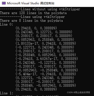
// Extract the lines from the polydata
vtkIdType numberOfLines = cutter->GetOutput()->GetNumberOfLines();
std::cout << "-----------Lines without using vtkStripper" << std::endl;
std::cout << "There are " << numberOfLines << " lines in the polydata" << std::endl;
numberOfLines = stripper->GetOutput()->GetNumberOfLines();
vtkPoints* points = stripper->GetOutput()->GetPoints();
vtkCellArray* cells = stripper->GetOutput()->GetLines();
std::cout << "-----------Lines using vtkStripper" << std::endl;
std::cout << "There are " << numberOfLines << " lines in the polydata"<< std::endl;
// Older implementations of vtkCellArray use internal iterator APIs (not thread safe):
vtkIdType* indices;
vtkIdType numberOfPoints;
unsigned int lineCount = 0;
for (cells->InitTraversal(); cells->GetNextCell(numberOfPoints, indices); lineCount++)
{
std::cout << "Line " << lineCount << ": " << std::endl;
for (vtkIdType i = 0; i < numberOfPoints; i++)
{
double point[3];
points->GetPoint(indices[i], point);
std::cout << "\t(" << point[0] << ", " << point[1] << ", " << point[2] << ")" << std::endl;
}
}
Toda la mitad de la parte es básicamente igual que el primer ejemplo, y la última parte son vtkCutterlas coordenadas del punto de salida de la línea de contorno;
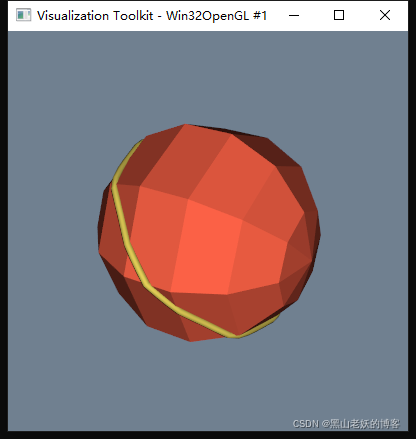
Curva de contorno de esfera cortada oblicuamente para formar una pantalla de tubo
vtkSmartPointer<vtkPolyData> polyData;
vtkNew<vtkSphereSource> modelSource;
modelSource->Update();
polyData = modelSource->GetOutput();

double length = polyData->GetLength();

vtkNew<vtkPlane> plane;
plane->SetNormal(0, 1, 1);
plane->SetOrigin(polyData->GetCenter());

vtkNew<vtkCutter> cutter;
cutter->SetInputData(polyData);
cutter->SetCutFunction(plane);
cutter->GenerateValues(1, 0.0, 0.0);

vtkNew<vtkNamedColors> colors;

vtkNew<vtkPolyDataMapper> modelMapper;
modelMapper->SetInputData(polyData);

vtkNew<vtkActor> model;
model->SetMapper(modelMapper);
model->GetProperty()->SetColor(colors->GetColor3d("Tomato").GetData());
model->GetProperty()->SetInterpolationToFlat();

vtkNew<vtkStripper> stripper;
stripper->SetInputConnection(cutter->GetOutputPort());

vtkNew<vtkKochanekSpline> spline;
spline->SetDefaultTension(.5);

vtkNew<vtkSplineFilter> sf;
sf->SetInputConnection(stripper->GetOutputPort());
sf->SetSubdivideToSpecified();
sf->SetNumberOfSubdivisions(50);
sf->SetSpline(spline);
sf->GetSpline()->ClosedOn();

vtkNew<vtkTubeFilter> tubes;
tubes->SetInputConnection(sf->GetOutputPort());
tubes->SetNumberOfSides(8);
tubes->SetRadius(length / 100.0);

vtkNew<vtkPolyDataMapper> linesMapper;
linesMapper->SetInputConnection(tubes->GetOutputPort());
linesMapper->ScalarVisibilityOff();

vtkNew<vtkActor> lines;
lines->SetMapper(linesMapper);
lines->GetProperty()->SetColor(colors->GetColor3d("Banana").GetData());

vtkNew<vtkRenderer> renderer;
renderer->UseHiddenLineRemovalOn();

vtkNew<vtkRenderWindow> renderWindow;
vtkNew<vtkRenderWindowInteractor> interactor;
interactor->SetRenderWindow(renderWindow);

// Add the actors to the renderer
renderer->AddActor(model);
renderer->AddActor(lines);

renderer->ResetCamera();
renderer->SetBackground(colors->GetColor3d("SlateGray").GetData());
renderer->GetActiveCamera()->Azimuth(300);
renderer->GetActiveCamera()->Elevation(30);
renderWindow->AddRenderer(renderer);
renderWindow->SetSize(400, 400);
renderWindow->SetWindowName("FitSplineToCutterOutput");

// This starts the event loop and as a side effect causes an initial
// render.
renderWindow->Render();
interactor->Start();

// Extract the lines from the polydata
vtkIdType numberOfLines = cutter->GetOutput()->GetNumberOfLines();

std::cout << "-----------Lines without using vtkStripper" << std::endl;
if (numberOfLines == 1) {


    std::cout << "There is " << numberOfLines << " line in the polydata" << std::endl;
}
else {


    std::cout << "There are " << numberOfLines << " lines in the polydata" << std::endl;
}
numberOfLines = stripper->GetOutput()->GetNumberOfLines();
vtkPoints* points = stripper->GetOutput()->GetPoints();
vtkCellArray* cells = stripper->GetOutput()->GetLines();

std::cout << "-----------Lines using vtkStripper" << std::endl;
if (numberOfLines == 1) {


    std::cout << "There is " << numberOfLines << " line in the polydata" << std::endl;
}
else {


    std::cout << "There are " << numberOfLines << " lines in the polydata" << std::endl;
}

// Older implementations of vtkCellArray use internal iterator APIs (not
// thread safe):
vtkIdType* indices;
vtkIdType numberOfPoints;
unsigned int lineCount = 0;
for (cells->InitTraversal(); cells->GetNextCell(numberOfPoints, indices); lineCount++) {


    std::cout << "Line " << lineCount << ": " << std::endl;
    for (vtkIdType i = 0; i < numberOfPoints; i++) {


        double point[3];
        points->GetPoint(indices[i], point);
        std::cout << "\t(" << point[0] << ", " << point[1] << ", " << point[2] << ")" << std::endl;
    }
}
Usa un plano inclinado para realizar la esfera Cut, después de obtener el contorno, interpola, y utilízalo vtkTubeFilterpara formar un tubo delgado para mostrar;
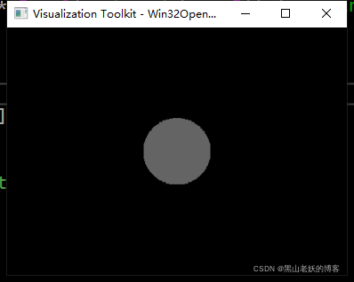
Convierta el contorno de la bola cortada en datos vtkImageData
Convierta el contorno cortado en una imagen bidimensional en escala de grises;
vtkNew<vtkSphereSource> sphereSource;
sphereSource->SetPhiResolution(30);
sphereSource->SetThetaResolution(30);
sphereSource->SetCenter(40, 40, 0);
sphereSource->SetRadius(20);

// generate circle by cutting the sphere with an implicit plane
// (through its center, axis-aligned)
vtkNew<vtkCutter> circleCutter;
circleCutter->SetInputConnection(sphereSource->GetOutputPort());
vtkNew<vtkPlane> cutPlane;
cutPlane->SetOrigin(sphereSource->GetCenter());
cutPlane->SetNormal(0, 0, 1);
circleCutter->SetCutFunction(cutPlane);

vtkNew<vtkStripper> stripper;
stripper->SetInputConnection(circleCutter->GetOutputPort()); // valid circle
stripper->Update();
renderPolygon(stripper->GetOutput());
// that's our circle
auto circle = stripper->GetOutput();
// prepare the binary image's voxel grid
vtkNew<vtkImageData> whiteImage;
double bounds[6];
circle->GetBounds(bounds);
double spacing[3]; // desired volume spacing
spacing[0] = 0.5;
spacing[1] = 0.5;
spacing[2] = 0.5;
whiteImage->SetSpacing(spacing);

// compute dimensions
int dim[3];
for (int i = 0; i < 3; i++) {


    dim[i] = static_cast<int>(ceil((bounds[i * 2 + 1] - bounds[i * 2]) / spacing[i])) + 1;
    if (dim[i] < 1)
        dim[i] = 1;
}
whiteImage->SetDimensions(dim);
whiteImage->SetExtent(0, dim[0] - 1, 0, dim[1] - 1, 0, dim[2] - 1);
double origin[3];

// NOTE: I am not sure whether or not we had to add some offset!
origin[0] = bounds[0]; // + spacing[0] / 2;
origin[1] = bounds[2]; // + spacing[1] / 2;
origin[2] = bounds[4]; // + spacing[2] / 2;
whiteImage->SetOrigin(origin);
whiteImage->AllocateScalars(VTK_UNSIGNED_CHAR, 1);

// fill the image with foreground voxels:
unsigned char inval = 100;
unsigned char outval = 0;
vtkIdType count = whiteImage->GetNumberOfPoints();
for (vtkIdType i = 0; i < count; ++i) {


    whiteImage->GetPointData()->GetScalars()->SetTuple1(i, inval);
}

// sweep polygonal data (this is the important thing with contours!)
vtkNew<vtkLinearExtrusionFilter> extruder;
extruder->SetInputData(circle);
extruder->SetScaleFactor(1.);
extruder->SetExtrusionTypeToVectorExtrusion();
extruder->SetVector(0, 0, 1);
extruder->Update();

// polygonal data --> image stencil:
vtkNew<vtkPolyDataToImageStencil> pol2stenc;
pol2stenc->SetTolerance(1); // important if extruder->SetVector(0, 0, 1) !!!
pol2stenc->SetInputConnection(extruder->GetOutputPort());
pol2stenc->SetOutputOrigin(origin);
pol2stenc->SetOutputSpacing(spacing);
pol2stenc->SetOutputWholeExtent(whiteImage->GetExtent());
pol2stenc->Update();

// cut the corresponding white image and set the background:
vtkNew<vtkImageStencil> imgstenc;
imgstenc->SetInputData(whiteImage);
imgstenc->SetStencilConnection(pol2stenc->GetOutputPort());
imgstenc->ReverseStencilOff();
imgstenc->SetBackgroundValue(outval);
imgstenc->Update();
imgstenc->GetOutput()->Print(std::cout);
vtkSmartPointer<vtkImageData> img = imgstenc->GetOutput();

vtkNew<vtkImageViewer2> imageViewer;
imageViewer->SetInputData(img);
vtkNew<vtkRenderWindowInteractor> renderWindowInteractor;
imageViewer->SetupInteractor(renderWindowInteractor);
imageViewer->Render();

renderWindowInteractor->Start();
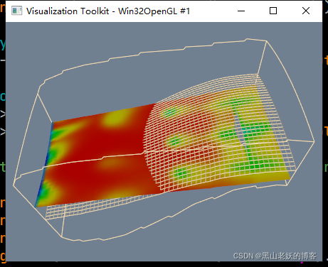
sección de fluidos
vtkNew<vtkNamedColors> colors;
vtkNew<vtkRenderer> ren1;

vtkNew<vtkRenderWindow> renWin;
renWin->AddRenderer(ren1);

vtkNew<vtkRenderWindowInteractor> iren;
iren->SetRenderWindow(renWin);

// cut data
vtkNew<vtkMultiBlockPLOT3DReader> pl3d;
pl3d->SetXYZFileName("D:\\combxyz.bin");
pl3d->SetQFileName("D:\\combq.bin");
pl3d->SetScalarFunctionNumber(100);
pl3d->SetVectorFunctionNumber(202);
pl3d->Update();

vtkStructuredGrid* sg = dynamic_cast<vtkStructuredGrid*>(pl3d->GetOutput()->GetBlock(0));

vtkNew<vtkPlane> plane;
plane->SetOrigin(sg->GetCenter());
plane->SetNormal(-0.287, 0, 0.9579);

vtkNew<vtkCutter> planeCut;
planeCut->SetInputData(pl3d->GetOutput()->GetBlock(0));
planeCut->SetCutFunction(plane);

vtkNew<vtkDataSetMapper> cutMapper;
cutMapper->SetInputConnection(planeCut->GetOutputPort());
cutMapper->SetScalarRange(sg->GetPointData()->GetScalars()->GetRange());

vtkNew<vtkActor> cutActor;
cutActor->SetMapper(cutMapper);

// extract plane
vtkNew<vtkStructuredGridGeometryFilter> compPlane;
compPlane->SetInputData(sg);
compPlane->SetExtent(0, 100, 0, 100, 9, 9);

vtkNew<vtkPolyDataMapper> planeMapper;
planeMapper->SetInputConnection(compPlane->GetOutputPort());
planeMapper->ScalarVisibilityOff();

vtkNew<vtkActor> planeActor;
planeActor->SetMapper(planeMapper);
planeActor->GetProperty()->SetRepresentationToWireframe();
planeActor->GetProperty()->SetColor(colors->GetColor3d("Wheat").GetData());

// outline
vtkNew<vtkStructuredGridOutlineFilter> outline;
outline->SetInputData(pl3d->GetOutput()->GetBlock(0));

vtkNew<vtkPolyDataMapper> outlineMapper;
outlineMapper->SetInputConnection(outline->GetOutputPort());

vtkNew<vtkActor> outlineActor;
outlineActor->SetMapper(outlineMapper);
outlineActor->GetProperty()->SetColor(colors->GetColor3d("Wheat").GetData());

// Add the actors to the renderer, set the background and size
ren1->AddActor(outlineActor);
ren1->AddActor(planeActor);
ren1->AddActor(cutActor);
ren1->SetBackground(colors->GetColor3d("SlateGray").GetData());

renWin->SetSize(640, 480);
renWin->SetWindowName("CutStructuredGrid");

auto camera = ren1->GetActiveCamera();
camera->SetPosition(5.02611, -23.535, 50.3979);
camera->SetFocalPoint(9.33614, 0.0414149, 30.112);
camera->SetViewUp(-0.0676794, 0.657814, 0.750134);
camera->SetDistance(31.3997);
camera->SetClippingRange(12.1468, 55.8147);

// render the image
renWin->Render();
iren->Start();
Cortar el cubo usando un avión.
vtkNew<vtkNamedColors> colors;
vtkNew<vtkCubeSource> cube;
cube->SetXLength(40);
cube->SetYLength(30);
cube->SetZLength(20);
vtkNew<vtkPolyDataMapper> cubeMapper;
cubeMapper->SetInputConnection(cube->GetOutputPort());

// Create a plane to cut,here it cuts in the XZ direction (xz
// normal=(1,0,0);XY =(0,0,1),YZ =(0,1,0)
vtkNew<vtkPlane> plane;
plane->SetOrigin(10, 0, 0);
plane->SetNormal(1, 0, 0);

// Create cutter
vtkNew<vtkCutter> cutter;
cutter->SetCutFunction(plane);
cutter->SetInputConnection(cube->GetOutputPort());
cutter->Update();

vtkNew<vtkPolyDataMapper> cutterMapper;
cutterMapper->SetInputConnection(cutter->GetOutputPort());
cutterMapper->SetResolveCoincidentTopologyToPolygonOffset();

// Create plane actor
vtkNew<vtkActor> planeActor;
planeActor->GetProperty()->SetColor(colors->GetColor3d("Yellow").GetData());
planeActor->GetProperty()->SetLineWidth(2);
planeActor->GetProperty()->SetAmbient(1.0);
planeActor->GetProperty()->SetDiffuse(0.0);
planeActor->SetMapper(cutterMapper);

// Create cube actor
vtkNew<vtkActor> cubeActor;
cubeActor->GetProperty()->SetColor(colors->GetColor3d("Aquamarine").GetData());
cubeActor->GetProperty()->SetOpacity(0.5);
cubeActor->SetMapper(cubeMapper);

// Create renderers and add actors of plane and cube
vtkNew<vtkRenderer> renderer;
renderer->AddActor(planeActor); // display the rectangle resulting from the cut
renderer->AddActor(cubeActor);  // display the cube

// Add renderer to renderwindow and render
vtkNew<vtkRenderWindow> renderWindow;
renderWindow->AddRenderer(renderer);
renderWindow->SetSize(400, 400);
renderWindow->SetWindowName("Cutter");

vtkNew<vtkRenderWindowInteractor> interactor;
interactor->SetRenderWindow(renderWindow);
renderer->SetBackground(colors->GetColor3d("Silver").GetData());
renderWindow->Render();

auto camera = renderer->GetActiveCamera();
camera->SetPosition(-37.2611, -86.2155, 44.841);
camera->SetFocalPoint(0.569422, -1.65124, -2.49482);
camera->SetViewUp(0.160129, 0.42663, 0.890138);
camera->SetDistance(104.033);
camera->SetClippingRange(55.2019, 165.753);

renderWindow->Render();
interactor->Start();

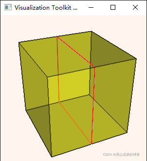
Cortar el hexaedro usando un plano.
vtkNew<vtkNamedColors> colors;

// Setup the coordinates of eight points
// (the two faces must be in counter clockwise order as viewed from the
// outside)
std::array<std::array<double, 3>, 8> pointCoords{

     {

    {

    {

    0.0, 0.0, 0.0}},
                                                  {

    {

    1.0, 0.0, 0.0}},
                                                  {

    {

    1.0, 1.0, 0.0}},
                                                  {

    {

    0.0, 1.0, 0.0}},
                                                  {

    {

    0.0, 0.0, 1.0}},
                                                  {

    {

    1.0, 0.0, 1.0}},
                                                  {

    {

    1.0, 1.0, 1.0}},
                                                  {

    {

    0.0, 1.0, 1.0}}} };

// Create the points and a hexahedron from the points.
vtkNew<vtkPoints> points;
vtkNew<vtkHexahedron> hexa;
for (auto i = 0; i < pointCoords.size(); ++i) {


    points->InsertNextPoint(pointCoords[i].data());
    hexa->GetPointIds()->SetId(i, i);
}

// Add the hexahedron to a cell array.
vtkNew<vtkCellArray> hexs;
hexs->InsertNextCell(hexa);

// Add the points and hexahedron to an unstructured grid.
vtkNew<vtkUnstructuredGrid> uGrid;
uGrid->SetPoints(points);
uGrid->InsertNextCell(hexa->GetCellType(), hexa->GetPointIds());

// Extract the outer (polygonal) surface.
vtkNew<vtkDataSetSurfaceFilter> surface;
surface->SetInputData(uGrid);
surface->Update();

vtkNew<vtkDataSetMapper> aBeamMapper;
aBeamMapper->SetInputConnection(surface->GetOutputPort());
vtkNew<vtkActor> aBeamActor;
aBeamActor->SetMapper(aBeamMapper);
aBeamActor->AddPosition(0, 0, 0);
aBeamActor->GetProperty()->SetColor(colors->GetColor3d("Yellow").GetData());
aBeamActor->GetProperty()->SetOpacity(0.60);
aBeamActor->GetProperty()->EdgeVisibilityOn();
aBeamActor->GetProperty()->SetEdgeColor(colors->GetColor3d("Black").GetData());
aBeamActor->GetProperty()->SetLineWidth(1.5);

// Create a plane to cut, here it cuts in the XZ direction
// (xz normal=(1,0,0); XY =(0,0,1), YZ =(0,1,0)
vtkNew<vtkPlane> plane;
plane->SetOrigin(0.5, 0, 0);
plane->SetNormal(1, 0, 0);

// Create cutter
vtkNew<vtkCutter> cutter;
cutter->SetCutFunction(plane);
cutter->SetInputData(aBeamActor->GetMapper()->GetInput());
cutter->Update();
vtkNew<vtkPolyDataMapper> cutterMapper;
cutterMapper->SetInputConnection(cutter->GetOutputPort());

// Create plane actor
vtkNew<vtkActor> planeActor;
planeActor->GetProperty()->SetColor(colors->GetColor3d("Red").GetData());
planeActor->GetProperty()->SetLineWidth(2);
planeActor->SetMapper(cutterMapper);

// Create a renderer, render window, and interactor
vtkNew<vtkRenderer> renderer;
vtkNew<vtkRenderWindow> renderWindow;
renderWindow->SetWindowName("DatasetSurface");
renderWindow->AddRenderer(renderer);
vtkNew<vtkRenderWindowInteractor> renderWindowInteractor;
renderWindowInteractor->SetRenderWindow(renderWindow);

// Add the actors to the scene
renderer->AddActor(aBeamActor);
renderer->AddActor(planeActor);
renderer->SetBackground(colors->GetColor3d("Seashell").GetData());

renderer->ResetCamera();
renderer->GetActiveCamera()->Azimuth(-25);
renderer->GetActiveCamera()->Elevation(30);

// Render and interact
renderWindow->Render();
renderWindowInteractor->Start();
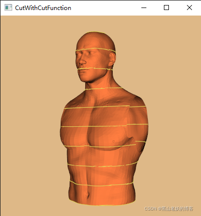
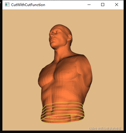
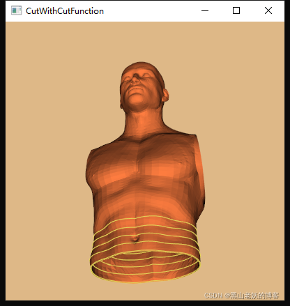
Dividir datos de polígonos de retrato usando planos
std::string inputFilename = "D:\\Torso.vtp";

int numberOfCuts = 10;
vtkNew<vtkNamedColors> colors;

vtkNew<vtkXMLPolyDataReader> reader;
reader->SetFileName(inputFilename.c_str());
reader->Update();

double bounds[6];
reader->GetOutput()->GetBounds(bounds);
std::cout << "Bounds: " << bounds[0] << ", " << bounds[1] << " " << bounds[2]
<< ", " << bounds[3] << " " << bounds[4] << ", " << bounds[5]
<< std::endl;

vtkNew<vtkPlane> plane;
plane->SetOrigin((bounds[1] + bounds[0]) / 2.0, (bounds[3] + bounds[2]) / 2.0,
    bounds[4]);
plane->SetNormal(0, 0, 1);

// Create cutter
double high = plane->EvaluateFunction((bounds[1] + bounds[0]) / 2.0, (bounds[3] + bounds[2]) / 2.0, bounds[5]);

vtkNew<vtkCutter> cutter;
cutter->SetInputConnection(reader->GetOutputPort());
cutter->SetCutFunction(plane);
cutter->GenerateValues(numberOfCuts, .99, .99 * high);

vtkNew<vtkPolyDataMapper> cutterMapper;
cutterMapper->SetInputConnection(cutter->GetOutputPort());
cutterMapper->ScalarVisibilityOff();

// Create cut actor
vtkNew<vtkActor> cutterActor;
cutterActor->GetProperty()->SetColor(colors->GetColor3d("Banana").GetData());
cutterActor->GetProperty()->SetLineWidth(2);
cutterActor->SetMapper(cutterMapper);

// Create model actor
vtkNew<vtkPolyDataMapper> modelMapper;
modelMapper->SetInputConnection(reader->GetOutputPort());
modelMapper->ScalarVisibilityOff();

vtkNew<vtkActor> modelActor;
modelActor->GetProperty()->SetColor(colors->GetColor3d("Flesh").GetData());
modelActor->SetMapper(modelMapper);

// Create renderers and add actors of plane and model
vtkNew<vtkRenderer> renderer;
renderer->AddActor(cutterActor);
renderer->AddActor(modelActor);

// Add renderer to renderwindow and render
vtkNew<vtkRenderWindow> renderWindow;
renderWindow->AddRenderer(renderer);
renderWindow->SetSize(400, 400);

vtkNew<vtkRenderWindowInteractor> interactor;
interactor->SetRenderWindow(renderWindow);

renderer->SetBackground(colors->GetColor3d("Burlywood").GetData());
renderer->GetActiveCamera()->SetPosition(0, -1, 0);
renderer->GetActiveCamera()->SetFocalPoint(0, 0, 0);
renderer->GetActiveCamera()->SetViewUp(0, 0, 1);
renderer->GetActiveCamera()->Azimuth(30);
renderer->GetActiveCamera()->Elevation(30);

renderer->ResetCamera();
renderWindow->Render();
renderWindow->SetWindowName("CutWithCutFunction");

interactor->Start();