Hardware interface refers to the connection method between two hardware devices. The hardware interface includes both the physical interface and the logical data transfer protocol.
| CVBS |
|---|
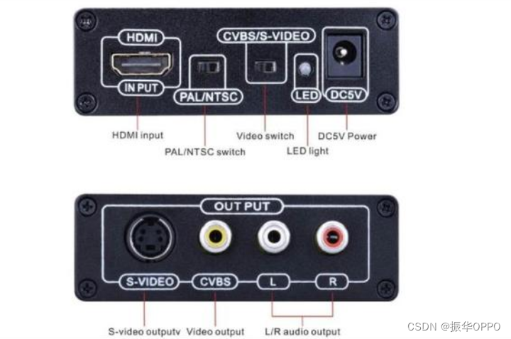
| The full English name of CVBS is Composite Video Broadcast Signal or Composite Video Blanking and Sync. Chinese translation for composite video broadcast signal or composite video blanking and synchronization . CVBS is a widely used standard, also called baseband video or RCA video, which is the traditional image data transmission method for (US) National Television Standards Committee (NTSC) television signals, which transmits data in analog waveforms. Composite video contains color difference (hue and saturation) and luminance (brightness) information , synchronized in a blanking pulse, transmitted with the same signal. |
It is a format in which an analog TV program (image) signal is combined with a sound signal and modulated into a radio frequency carrier. In fast-scan NTSC television, the very high frequency (VHF) or ultra-high frequency (UHF) carrier is the modulation amplitude used for composite video, and the resulting signal is approximately 6MHz wide. Some CCTV systems use coaxial cable to transmit composite video at short distances, and some DVD players and video tape recorders (VCRs) provide composite video input and output through a RCA socket, also known as an RCA connector.
In composite video, the interference of chromatic aberration and luminance information is inevitable, especially when the signal is weak. That's why long-range NTSC stations using VHF or UHF with old whip antennas, "rabbit ears", or outdoor "air" often contain fake or bobbing colors. CVBS is an older display method, more precisely the first generation video display output method (the second generation is S-VIDEO, the third generation is VGA, the fourth generation is DVI, and the fifth generation is HDMI).
In the current system integration project, especially the long-distance transmission of VGA signals is a relatively common problem in the project. The so-called transmission system refers to all links from the computer exit to the display part entrance, including distributors, matrixes, cables and graphics controllers. And so on, due to the long distance of signal transmission, the influence of the parameters of the transmission system and the surrounding electromagnetic environment on the signal quality cannot be ignored. Common phenomena are: image blurring, darkening, trailing and ghosting, and image display Stability (such as: jumping or black screen, etc.), etc., the reasons for the above phenomena are different, and the solutions are different.
We divide it into four categories:
- The image is blurred, darkened and smeared due to the amplitude-frequency characteristics and group delay characteristics of the transmission system;
- High-frequency interference due to equipment self-excitation or environmental electromagnetic interference;
- Low frequency interference caused by improper handling of the system power supply ground wire;
- Ghost reflection and display instability caused by impedance mismatch of equipment or transmission system or connectors.
| VGA |
|---|
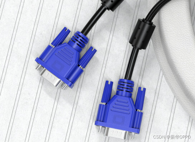
| VGA (Video Graphics Array) is a computer display standard proposed by IBM in 1987 using analog signals. The VGA interface is a special interface for the computer to output data using the VGA standard. The VGA interface has a total of 15 pins and is divided into 3 rows with 5 holes in each row. It is the most widely used interface type on graphics cards, and most graphics cards have this type of interface. It transmits red, green, and blue analog signals as well as sync signals (horizontal and vertical signals). |
VGA has the advantages of high resolution, fast display rate and rich colors. VGA interface is not only the standard interface of CRT display equipment, but also the standard interface of LcD liquid crystal display equipment, which has a wide range of applications.
With the development of electronic industry and video image processing technology, VGA (Video Graphics Array) has been widely used in video and computer fields as a standard display interface. The high-resolution image is displayed on the monitor in real time. Generally, the frequency of the crystal oscillator is required to be above 40MHz. It is difficult for traditional electronic circuits to achieve this speed. If a special image processing chip is used, the design difficulty and the high development cost become a bottleneck choice.
The color difference VGA interface (D-Sub interface) of the common interface, when it comes to the VGA interface, I believe many friends are familiar with it, because this interface is the most important interface on the computer monitor. Since the era of huge CRT monitors, the VGA interface It has been used and has been used to this day. In addition, the VGA interface is also called the D-Sub interface.
Many people think that only the HDMI interface can transmit high-definition signals, but this is a misunderstanding that everyone is easy to enter, because the VGA connection can also display 1080P images, and even the resolution can reach higher, so use it to connect the display device. There is no problem to watch high-definition video, and although it is an analog interface, because VGA decomposes the video signal into R, G, B three primary colors and HV line and field signals for transmission, the loss in transmission is quite small.
The VGA interface is a D-type interface with a total of 15 pinholes, divided into three rows of five. Among them, in addition to 2 NC (Not Connect) signals, 3 display data buses and 5 GND signals, the more important are 3 RGB color component signals and 2 scan synchronization signals HSYNC and VSYNC pins. The color components in the VGA interface use the RS343 level standard. The peak voltage of the RS343 level standard is 1V. The VGA interface is the most widely used interface type on graphics cards, and most graphics cards have this interface. Some graphics cards that do not have a VGA interface but have a DVI (Digital Visual Interface) interface can also convert the DVI interface into a VGA interface through a simple adapter. Usually, the graphics card without a VGA interface will come with such an adapter. .
Most computers and external display devices are connected through an analog VGA interface. The display image information digitally generated inside the computer is converted into R, G, B three primary color signals and line and field signals by the digital/analog converter in the graphics card. Synchronization signal, the signal is transmitted to the display device through the cable. For analog display devices, such as analog CRT displays, the signal is directly sent to the corresponding processing circuit to drive and control the picture tube to generate images. For digital display devices such as LCD and DLP, corresponding A/D (analog/digital) converters need to be configured in the display device to convert analog signals into digital signals. After two conversions of D/A and A/D, some image details are inevitably lost. It is understandable that the VGA interface is used in CRT monitors, but if it is used to connect display devices such as liquid crystals, the image loss during the conversion process will slightly reduce the display effect.
And you can judge from the interface whether the graphics card is a standalone display or an integrated graphics card. The vertical position of the VGA port indicates an integrated graphics card, and the horizontal position of the VGA port indicates a discrete graphics card (general desktop hosts can use this method to view).
| Two |
|---|
| The full English name of DVI is Digital Visual Interface, and the Chinese name is "Digital Video Interface". It is a video interface standard designed to transmit uncompressed digital video. Widely used in LCD, digital projector and other display equipment. This standard is developed by a forum composed of several leading manufacturers in the display industry: "Digital Display Working Group" (DDWG). The DVI interface can send uncompressed digital video data to the display device. This specification is partially compatible with the HDMI standard. |
The protocol of the DVI interface causes the pixel brightness and color signals to be sent in binary form from the signal source (such as a graphics card) to the display device. When the display device is driven at its native resolution, it is only necessary to read the value data for each pixel from the DVI and apply it to the correct location. Compared with the pixel data sent in the analog mode, it will be affected by adjacent pixel data, electromagnetic noise and other analog lossy effects. In this method, each pixel in the output register directly corresponds to each pixel on the display. Make the picture quality have a basic guarantee.
Previous standards for sending video data in analog, such as VGA, were designed for display devices based on kinescopes (cathode ray tubes), and the units of transmission were horizontal scan lines, so digitized discrete signals were not used. The video signal sent by analog is to change the output voltage to control the density of the electron beam in scanning, and thereby express the brightness and chroma.
However, when a digital display device such as an LCD is put into practical use, when a signal is sent to a digital display device in an analog manner, the device must sample the scan line signal at a specific frequency and then convert it back to a digital format. If the sampling error occurs, the picture quality will be degraded, but the actual picture of DVI under 19 inches is not significantly different from the D-SUB output picture quality. And when the signal source is a computer, the process that the graphics card converts the digital picture signal into an analog output, and then is converted back to a digital picture by the LCD display is obviously redundant. Therefore, DVI is also widely used as LCD monitors become mainstream.

In addition to the digital signal pins specified in the DVI standard, the DVI connector can also include traditional analog signal (VGA) pins. This design is to maintain the versatility of DVI so that different forms of display screens can share the same connection cable. With the different implementation functions, DVI connectors are divided into three types:
- DVI-D (Digital digital signal; single link or dual link)
- DVI-A (Analog analog signal)
- DVI-I (Integrated; both digital and analog; single link or dual link)
- In addition, there is a connector that realizes a second group of DVI chains called DVI-DL (dual link) to emphasize the transmission capability.
Some newer DVD players, televisions (including HDTVs) and projectors use a so-called "DVI/HDCP" connector, which is exactly the same as DVI in appearance, but the data it sends is encrypted by the HDCP protocol. to prevent illegal copying. Computers equipped with DVI interface graphics cards today can often use the aforementioned display devices as large display screens, but since most graphics cards produced before 2007 do not support HDCP, they may be limited by copyright protection technology and cannot display the highest resolution. Play HDCP protected video content.
In addition, the analog pins of DVI-D are intentionally shorter than the same pins of DVI-I to prevent users from mistakenly inserting the DVI-I male connector into the DVI-D female socket.
| HDMI |
|---|
| High Definition Multimedia Interface (HDMI) is a fully digital video and sound transmission interface that can transmit uncompressed audio and video signals. HDMI can be used in equipment such as set-top boxes, DVD players, personal computers, TVs, game consoles, integrated amplifiers, digital audio and TV sets. HDMI can send audio and video signals at the same time. Since the audio and video signals use the same wire, the installation difficulty of the system line is greatly simplified. |
HDMI is designed to replace the older analog signal audio and video transmission interface such as SCART or RCA and other terminals. It supports a variety of TV and computer video formats, including SDTV, HDTV video images, plus multi-channel digital audio. Both HDMI and UDI, which removes the audio transmission function, inherit the core technology of DVI, "Transmission Minimized Differential Signal" TMDS, which is still an extension of DVI in essence. The video content of DVI, HDMI and UDI is transmitted in real-time and dedicated line mode, which can ensure that the phenomenon of blockage will not occur when the video traffic is large. The amount of data per pixel is 24 bits. The timing of the signals is very similar to that of VGA. The picture is sent line by line, and a specific blank time (similar to an analog scan line) is added after each line and frame of the picture is sent, and the data is not "Micro-Packet Architecture (micro data packet architecture)" It will not only update the parts that have changed in the two frames before and after. Each frame will be resent in its entirety during this update. When the specification was initially formulated, its maximum pixel transfer rate was 165Mpx/sec, which was sufficient to support 1080p image quality at 60 frames per second, or UXGA resolution (1600x1200); it was later expanded to 340Mpx/sec in the HDMI 1.3 specification to match future possibilities demand.

DisplayPort was developed for liquid crystal displays at the beginning, using the "Micro-Packet Architecture" transmission architecture, and the video content is transmitted in data packets, which is obviously different from video transmission technologies such as DVI and HDMI. That is to say, the emergence of HDMI replaced analog signal video, and the emergence of DisplayPort replaced DVI and VGA interfaces.
HDMI also supports uncompressed 8-channel digital audio transmission (sampling rate 192kHz, data length 24bits/sample), and any compressed audio stream such as Dolby Digital or DTS, and also supports 8-channel 1bit DSD signal used by SACD. In the HDMI 1.3 specification, support for uncompressed audio streams with ultra-high data volumes such as Dolby TrueHD and DTS-HD is added.
The standard Type A HDMI connector has 19 pins, and another Type B connector that supports higher resolutions has been defined, but no manufacturer uses the Type B connector. The Type B connector has 29 pins, allowing it to send extended video channels to meet future high-quality requirements, such as WQSXGA (3200x2048).
Type A HDMI is backward compatible with the Single-link DVI-D or DVI-I interface (but not DVI-A) used by most monitors and graphics cards today, which means that the signal source using the DVI-D interface can pass the conversion cable. Drive HDMI display, but this conversion scheme does not support audio transmission and remote control functions. In addition, DVI displays without HDCP certification will not be able to watch the video data output from HDMI with HDCP encryption protection (all HDMI displays support HDCP, but most DVI displays do not support HDCP), Type B HDMI connector Will also be backward compatible with Dual-link DVI interface.
The initiators of the HDMI organization include major consumer electronics manufacturers, such as Hitachi, Panasonic, Quasar, Philips, Sony, Thomson RCA, Toshiba, Silicon Image. Digital Content Protection, LLC provides copy protection technology related to HDMI interface. In addition, HDMI is also supported by major film production companies such as 20th Century Fox, Warner Bros., Disney, major consumer electronics manufacturers including Samsung Electronics, and many cable system operators.
| MIPI |
|---|
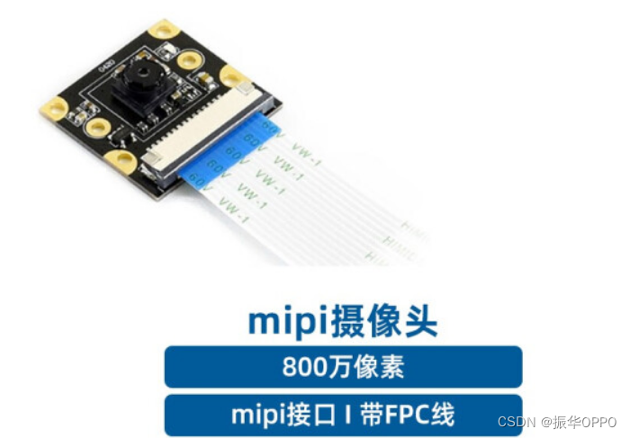
| MIPI Alliance, the Mobile Industry Processor Interface (MIPI) Alliance. MIPI (Mobile Industry Processor Interface) is an open standard and a specification for mobile application processors initiated by the MIPI Alliance. |
There are different WorkGroups under the MIPI Alliance, which define a series of mobile phone internal interface standards, such as camera interface CSI, display interface DSI , radio frequency interface DigRF, microphone/speaker interface SLIMbus, etc. The advantage of a unified interface standard is that mobile phone manufacturers can flexibly choose different chips and modules from the market according to their needs, making it faster and more convenient to change designs and functions.
-
DSI defines a high-speed serial interface between the processor and the display module.
-
CSI defines a high-speed serial interface between the processor and the camera module.
-
D-PHY: Provides physical layer definitions for DSI and CSI.
| RCA |
|---|
| RCA interface, also known as lotus socket, AV terminal (Composite video connector, also known as composite terminal), is a common terminal used by household audio-visual appliances to send video analog signals (such as NTSC, PAL, SECAM) . AV terminals usually use yellow RCA terminals to transmit video signals, and two red and white RCA terminals to send audio, also known as three-color lines/red-white-yellow lines . |
What is transmitted in the RCA interface is the three source elements of the analog TV signal: Y, U, V, and the pulse signal as the synchronization reference. Y stands for the brightness of the video (luminance, also known as brightness), and contains the sync pulse, as long as the Y signal is present, you can see black and white TV images (in fact, this is the way color TV is compatible with early black and white TV). The color information is carried between the U signal and the V signal. U and V are first mixed into two sets of quadrature phases in one signal (the mixed signal is called chrominance), and then added with the Y signal. total. Since Y is the baseband signal and UV is mixed with the carrier, this summing action is equivalent to frequency division multiplexing.
Generally speaking, digital audio-visual systems mainly have analog video input/output and analog audio input/output ports.
Through the analog video line, it can be directly recognized by the player with the composite video input/output port, then the video input/output port is connected to the digital audio-visual system port. Take a TV set as an example, because ordinary TV sets only receive analog signals, and the signals stored on DV tapes are digital signals, and the two are not compatible originally. However, through the analog video output/input port of the digital audio-visual system, the content on the DV tape can be directly played on the TV. This port is the analog video output. This process is called digital signal/analog signal conversion (D/A conversion).
On the contrary, connect the TV and the digital audio-visual system with a signal line, and the digital audio-visual system can use its DV tape to record TV programs. This process is the analog-to-digital process, that is, analog/digital signal conversion (A/D conversion).

| SDI |
|---|
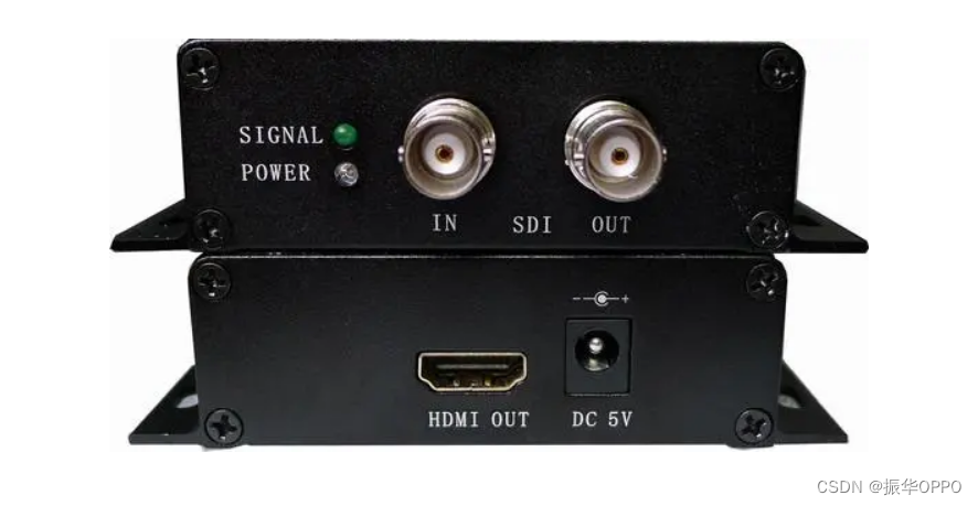
| SDI interface is an acronym for serial digital interface. The HD-SDI interface is a broadcast-grade high-definition digital input and output port, where HD represents a high-definition signal. Since the SDI interface cannot directly transmit compressed digital signals, after the compressed signals recorded by digital video recorders, hard disks and other equipment are played back, they must be decompressed and input through the SDI interface before they can enter the SDI system. If the decompression and compression are repeated repeatedly, the image quality will be degraded and the time delay will increase. Therefore, digital video recorders and non-linear editing systems of various formats stipulate their own interfaces for directly transmitting compressed digital signals. |
In the fields of non-editing post-production, broadcasting stations, etc., HD-SDI is widely used. It is an interface specification for transmission under the signal rate of 1.485Gb/s or 1.485/1.001Gb/s according to SMPTE292M. This specification specifies data format, channel coding method, signal specification of coaxial cable interface, connector and cable type and optical fiber interface. The HD-SDI interface adopts coaxial cable, and the BNC interface is used as the cable standard. The effective distance is 100M.
Advantages of HD-SDI monitoring system:
Since the equipment is connected by BNC interface, that is to say, in the process of converting the existing traditional analog frame system into a high-definition monitoring system, there is no need to re-wiring, but only the front-end and back-end parts need to be replaced, which will save a huge amount of time for the project. cost and labor costs.
- Ease of use
Because the system framework used in the engineering construction of HD-SDI camera products is the same as that of the analog monitoring system, the system wiring can be realized by using 75-5 coaxial cables, and construction personnel and system operators do not need training and are easier to use. - Unlike IP surveillance, the uncompressed
HD-SDI camera compresses and packages the video signal and transmits it over the network. It transmits the uncompressed digital signal at high speed on the coaxial cable, and the original image will not be distorted. - High-definition real-time
HD-SDI camera monitoring is not affected by the transmission network, and there is no image delay problem caused by IP network monitoring, in the occasions where real-time monitoring and high-definition requirements are required. - High utilization rate
HD-SDI camera equipment video output image resolution is 1920 × 1080, and the density of camera points per unit area is greatly reduced. Provide more detailed processing in monitoring places, such as seeing faces and license plates clearly.
Interface principle
A serial interface is an interface that sequentially transmits individual bits of a data word and corresponding data through a single channel. Due to the high data rate of serial digital signals, they must be processed before transmission. Scrambled non-return-to-zero inversion (NRZI) was used to replace earlier block coding, the standards of which were SMPTE-259M and EBU-Tech-3267, which included digital composite and digital component signals including digital audio. Before transmission, the original data stream is scrambled and converted to NRZI codes to ensure reliable recovery of the original data at the receiving end. In this way, the digital serial interface can be conceptually understood as a baseband signal modulation. The SDI interface can pass the serial digital component signal of 270Mb/s. For the 16:9 format image, it should be able to transmit the signal of 360Mb/s.
NRZI codes are polarity sensitive codes. "1" and "0" are used to represent the high and low levels. If there is a long-term continuous "1" or continuous "0", it will affect the receiving end to extract the clock from the digital signal. Because the serial digital signal interface does not transmit the clock signal alone, the receiving end needs to extract the clock signal from the digital signal stream, so the NRZI code with "1" and "0" to indicate whether there is a level conversion is used. When receiving the NRZI stream, as long as the level change is detected, the data can be recovered. Even if it is all "1" signals, the resulting signal frequency is only half of the original clock frequency. After scrambling, the chance of continuous "1" is reduced. , which further reduces the high-frequency components. At the receiving end of the data stream, the original data stream is recovered from the NRZI code stream by the SDI decoder.
(a) Serial Digital Data Interface SDDI (Serial Digital Data Interface), used for Betacam-SX non-linear editing or digital news transmission system, through this interface, 4 times speed can be uploaded from tape to disk.
(b) 4x speed serial digital interface QSDI (QuarterSerial Digital Interface), in the DVCAM video recorder editing system, through this interface at 4x speed upload from tape to disk, download from disk to tape or copy data between disk and disk .
(c) Compression Serial Digital Interface CSDI (CompressionSerial Digital Interface), used in DVCPRO and Digital-S digital video recorder, non-linear editing system, can transfer data at 4 times speed from tape base to disc base or between disc bases.
The above three interfaces are not compatible with each other, but all are compatible with the SDI interface. In a 270Mb/s SDI system, high-speed transmission is possible. These three interfaces are designed for establishing digital audio and video networks. This type of network does not use handshake protocols like computer networks, but uses synchronous network technology, which will not cause delays due to different paths. People often embed digital audio signals in SDI signals, that is, insert digital audio signals into the horizontal and vertical sync pulses (horizontal and vertical blanking) of the video signal and transmit at the same time as the digital component video signal.
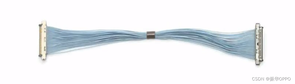
| LVDS |
|---|
| LVDS (Low-Voltage Differential Signaling) low-voltage differential signal is a differential signal technology with low power consumption, low bit error rate, low crosstalk and low radiation . This transmission technology can reach more than 155Mbps. The core of LVDS technology is to use Very low voltage swing high-speed differential data transmission, which can realize point-to-point or point-to-multipoint connection. The transmission medium can be copper PCB connection or balanced cable. |
LVDS (Low Voltage Differential Signaling) is a low-amplitude differential signaling technology. It uses very low amplitude signals (about 350mV) to transmit data over a pair of differential PCB traces or balanced cables. It can transmit serial data at speeds up to several thousand Mbps. Due to the low amplitude of the voltage signal and the use of constant current source mode driving, it only generates extremely low noise and consumes very little power, and the power consumption is almost unchanged regardless of the frequency. In addition, because LVDS transmits data differentially, it is less susceptible to common-mode noise.
Background
With the continuous advancement of electronic design technology, the interconnection of high-speed signals and the application of broadband channels are increasing day by day, and the amount of data that needs to be transmitted is increasing and the speed is getting faster and faster. At present, the existing point-to-point physical layer interfaces such as RS-422, RS-485, SCSI and other data transmission standards, due to inherent limitations in speed, noise, EMI/EMC, power consumption, cost, etc., make it increasingly Incompetent for practical application. Also with the development of military electronic technology, in the field of space communication, such as tracking and data relay satellite system (TDSS), in order to achieve high-speed data relay and ranging, speed measurement must first solve the problems of high transmission rate and occupied bandwidth. In the field of radar applications, the emergence of various new radar systems and applications in different fields such as broadband detection and electronic countermeasures also inevitably face the problem of high-speed data collection and transmission; therefore, the use of new I/O Interface technology to solve the bottleneck problem of data transmission is becoming increasingly prominent.
LVDS has increasingly become the preferred interface standard for broadband high-speed system design due to its inherent characteristics of low voltage, low power consumption and favorable for high-speed transmission. At present, the application of LVDS technology in the communication field is becoming more and more popular, especially in base stations, large switches and other high-speed data transmission systems, LVDS is playing an irreplaceable role.
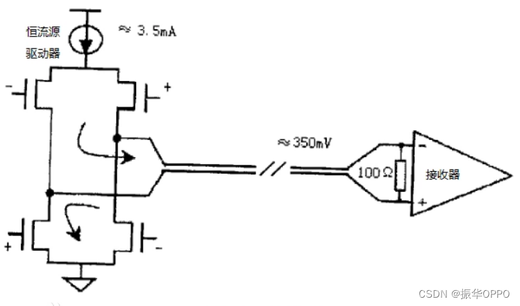
Fundamental
The basic working principle of LVDS is shown in the figure below. The source side driver consists of a constant current source (usually about 3.5mA, the maximum does not exceed 4mA) to drive a pair of differential signal lines. The receiver itself at the receiving end has a high DC input impedance, so almost all the drive current flows through the 100Ω termination matching resistor and generates a voltage of about 350mV at the receiver input. When the driving state of the source end changes, the direction of the current flowing through the matching resistor changes, so that the high and low logic states of the receiving end change.
In order to adapt to the change of the common mode voltage in a wide range, in general, the receiver input stage of LVDS also includes an automatic level adjustment circuit, which adjusts the common mode voltage to a fixed value, followed by a Schmitt trigger. Moreover, in order to prevent the instability of the Scdhmitt trigger, the design has a certain hysteresis characteristic, and the latter stage of the Schmitt is the differential amplifier.
Technical Features
The reason why LVDS has become the preferred signal form of high-speed I/O interface to solve the limitation of high-speed data transmission is because it has advantages in transmission speed, power consumption, anti-noise, EMI and so on.
- High-speed transmission capability : According to the LVDS standard defined by ANS/EIA/EIA-64, the theoretical limit rate is 1.923Gbps. The working mode of constant current source mode and low swing output determines that IVDS has high-speed driving capability.
- Low power consumption characteristics : LVDS devices are implemented with CMOS technology, and CMOS can provide low static power consumption; when the driving current of the constant current source is 3.5mA, the power consumption of the load (100Ω terminal matching) is only 1.225mW; The power consumption of LVDS is constant and does not rise relative to frequency like the dynamic power consumption of CMOS transceivers. The drive design of constant current source mode reduces system power consumption and greatly reduces the influence of frequency components on power consumption. Although the power consumption of CMOS is smaller than that of LVDS when the rate is low, as the frequency increases, the power consumption of CMOS will gradually increase, and eventually it needs to consume more power than LVDS. Generally, when the frequency is equal to 200MSps, the power consumption of LVDS and CMOS is about the same.
- Low supply voltage : With the development of integrated circuits and the requirement for higher data rates, low-voltage power supply is urgently needed. Reducing the supply voltage not only reduces the power consumption of high-density integrated circuits, but also reduces the heat dissipation pressure inside the chip, which helps to improve the integration level. LVDS drivers and receivers do not depend on specific supply voltage characteristics, which determines that it occupies the top spot in this regard.
- Strong anti-noise ability : The inherent advantage of differential signals is that noise is coupled on a pair of differential lines in the form of common mode, and is subtracted in the receiver, so that noise can be eliminated, so LVDS has strong anti-common mode. noise capability.
- Effectively suppress electromagnetic interference : Since the polarities of the differential signals are opposite, the electromagnetic fields radiated by them can cancel each other. The tighter the coupling, the less electromagnetic energy is released to the outside world, that is, the EMI is reduced.
- Accurate timing positioning : Because the switching change of the differential signal is located at the intersection of the two signals. Unlike ordinary single-ended signals, which rely on two threshold voltages, high and low, it is less affected by process and temperature, which can reduce timing errors, which is conducive to the effective transmission of high-speed digital signals.
- Adapt to a wide range of ground plane voltage changes : LVDS receivers can withstand at least ±1V ground voltage changes between the driver and the receiver. Since the typical bias voltage of an IVDS driver is +1.2V, the sum of the voltage variation of ground, the bias voltage of the driver, and the noise that is lightly coupled to it, is the common-mode voltage at the input of the receiver with respect to the ground of the driver. When the swing does not exceed 400mV, this common mode range is +0.2V~ +2.2V, and then, in general, the input voltage range of the receiver can vary from 0V~+2.4V.
It is precisely because LVDS has the above-mentioned main characteristics that HyperTransport (by AMD, Irfiniband (ly Intel), PCI-Express (by Intel) and other third-generation I/O bus standards (3G IO) invariably connect low-voltage differential signals ( IVDS) as the next-generation high-speed signal level standard.