Video for Linux two (Video4Linux2) referred V4L2, V4L2 is linux operating system for acquiring images, the API interface to the video and audio data, with appropriate video capture devices and corresponding drivers can realize images, video, audio, etc. collection. In remote conferencing, video telephony, video surveillance systems and embedded multimedia terminal has a wide range of applications.
一、Video for Linux two
In Linux, all peripherals are seen as a special kind of file, a "device file", you can access like ordinary file to read and write. In general, using the camera driving device V4L2 file is / dev / v4l / video0. For GM, you can create a link to / dev / video0 of. V4L2 supports two ways to capture images: memory mapping mode (the mmap) and the direct access (read). V4L2 defines a number of important data structures include / linux / videodev.h document, during the collection of images, that is, to obtain the final image data by the operation of these data. Linux systems can be configured V4L2 capabilities in the Linux kernel compile phase, by default have this development interface. V4L2 began to emerge from the Linux 2.5.x kernel versions.
V4L2 specification only defines a generic API elements (Common API Elements), an image format (Image Formats), input / output method (Input / Output), Linux kernel driver also defines a series of processing video information Interface (Interfaces), these interfaces are:
Video Capture Interface --Video Capture Interface;
Video output interface - Video Output Interface;
Video Overlay / Preview interfaces --Video Overlay Interface;
Video output interfaces cover --Video Output Overlay Interface;
Codec Interface --Codec Interface.
Second, the application of the principle of video capture by V4L2
V4L2 support memory-mapped mode (mmap) and direct read mode (read) to collect data, the former general for continuous capture of video data, which is often used to collect the data of still pictures, video capture article focuses on memory-mapped mode.
Via a five-step application interfaces V4L2 capture video data:
First, open a video file device performs parameter initialization video capture, video acquisition window provided by the interface V4L2 collected dot size and format;
Next, apply a number of video capture frame buffer, and the frame buffer mapping from kernel space to user space, to facilitate the application read / processed video data;
Third, the application to the input video capture frame buffer queuing, and video capture start;
Fourth, the drive start collecting, the application of video data taken from a video capture frame buffer output queue, after processing, the video capture frame buffer back into the input queue, the cycle used to capture the video data;
Fifth, stop video capture.
1. Initialize video capture
In Linux, the camera has been mapped to the hardware device file "/ dev / video0", open the file open function device, which file descriptor is obtained fd_v4l2, then this parameter initialization file descriptor.
Parameter acquisition window (1) is provided a video
Acquisition window is provided to set a video capture area within the shooting range of the camera apparatus. The main structure is v4l2_crop assignment, v4l2_crop v4l2_buffer_type constituted by a type of enumerated type and structure type v4l2_rect c, to describe the type and size of video acquisition window. type set as the type of video capture V4L2_BUF_TYPE_VIDEO_CAPTURE. c is a structure the size of the acquisition window, and its members Top Left respectively the abscissa and ordinate represent the start video capture area, width and height represent the width and height of image acquisition. After the assignment, set the fd_v4l2 ioctl function by using this structure.
struct v4l2_crop { enum v4l2_buf_type type;
struct v4l2_rect c;
};
(2) Set the video format and the dot size of a dot
The main structure is v4l2_format assign, and which consists of type FMT consortium, to describe the current behavior format video and data equipment.
Assigned to the type of video capture type V4L2_BUF_TYPE_VIDEO_CAPTURE, means that the definition of a stream type of video capture buffer. In fmt, pix v4l2_pix_format type structure is a graphic format. Pix needs to be set in several variables, PixelFormat represents capture format, to V4L2_PIX_FMT_YUV420; width, height representation of the image width, height, bytes; sizeimage storage space occupied by an image showing the size, in bytes ; bytesperline number of bytes per line. After the assignment, with the ioctl function to set fd_ v4l2 by this structure.
struct v4l2_format
{ enum v4l2_buf_type type;
union
{ struct v4l2_pix_format pix; // V4L2_BUF_TYPE_VIDEO_CAPTURE
struct v4l2_window win; // V4L2_BUF_TYPE_VIDEO_OVERLAY
__u8 raw_data[200]; // user-defined
} fmt;
};
(3) setting a frame rate of video capture
V4l2_streamparm structure attributes of the video stream will be described, which consists of type and Commonwealth parm. type above, since the election is V4L2_BUF_TYPE_VIDEO_CAPTURE, so only set v412_capture type structure can capture the parm. Wherein, v4l2_fract timeperframe type structure represented by the average percentage of each frame time, numerator and denominator by the elements together determine the duration of numerator / denominator; capturemode and said acquisition mode, acquisition of high-quality images is 1, the general It is set to 0. After the assignment, with the ioctl function to set fd_ v4l2 by this structure.
struct v4l2_streamparm
{ enum v4l2_buf_type type;
union
{ struct v4l2_captureparm capture;
struct v4l2_outputparm output;
__u8 raw_data[200]; /* user-defined */
} parm;
};
2. Application and video capture frame buffer provided
After the initialization is completed early, just to solve the problem of a size and format of the video data, and video frame data acquisition requires continuous manner to solve the frame buffer queue, i.e. by the driver to apply several frame buffer in memory to store video data.
Application by the method (VIDIOC_REQBUFS) API interface provides a plurality of application data video frame buffer, the frame buffer is generally the number of applications is not less than three, each storing a video frame buffer data, the frame buffer in the kernel space.
The application queries the length to the frame buffer address and offset in the kernel space by query method (VIDIOC_QUERYBUF) API interfaces provided.
Applications through the memory mapping method (the mmap), will apply to the frame buffer kernel space to user address space is mapped address, so it can process the data directly to the frame buffer.
(1) in the frame buffer video input queuing, and video capture start
During the processing of a video driver, defines two queues: video capture input queue (incoming queues) video capture and output queue (outgoing queues), the former is driven to store video data waiting queue, which is the driver has put video data into the queue. as shown in picture 2.
Application requires the frame buffer to input queuing (VIDIOC_QBUF) video capture and video capture can be started.
(2) cyclical, continuous video data collected
After starting the video capture driver to start collecting a data, the collected data into the video capture input queue a first frame buffer, a data acquisition is complete, i.e. the first frame buffer becomes full frame data after the driver moves the video capture frame buffer output queue, waits for the application is removed from the output queue. Next, the driver next frame of data acquisition, the second into the frame buffer, the same frame after the next frame buffer becomes full of data, it is placed in the output queue video capture.
Application is removed from the video capture frame buffer output queue containing video data, processing the video data in the frame buffer, such as a memory or compressed.
Finally, the application will process the frame buffer complete capture video data back into the input queue, so that the cycle can be acquired, as shown in FIG.

FIG 1 video capture input and output queuing
(3) finally stop the acquisition, release the memory frame buffer
3. The video capture program flow and associated with the API V4L2
V4L2 video capture device operating substantially in accordance with the open video, the video format is provided, start the video capture, video data loop process, stop the video capture, video equipment close, ioctl specific operation achieved by other functions. General procedure is as follows:
(1) Open V equipment. int fd = open ( "/ dev / video0", O_RDWR);
(2) the ability to query video equipment, such as whether the input video or audio input and output. ioctl (fd_v4l, VIDIOC_QUERYCAP, & cap)
(3) setting parameters of video capture
Setting of the video format, including standard PAL / NTSC, using the ioctl (fd_v4l, VIDIOC_S_STD, & std_id)
Sized video image capture window using the ioctl (fd_v4l, VIDIOC_S_CROP, & crop)
Provided video frame format, a frame format including a dot, the width and height, using ioctl (fd_v4l, VIDIOC_S_FMT, & fmt)
Setting the video frame rate, using ioctl (fd_v4l, VIDIOC_S_PARM, & parm)
Video rotatably provided using ioctl (fd_v4l, VIDIOC_S_CTRL, & ctrl)
(4) apply to the drive frame buffer video stream data
Request / application several frame buffers, typically less than 3, using the ioctl (fd_v4l, VIDIOC_REQBUFS, & req)
Inquiry frame buffer in the kernel space length and offset ioctl (fd_v4l, VIDIOC_QUERYBUF, & buf)
(5) through memory mapping application, the mapping of the frame buffer address space to the user, so that the operation can be collected directly to the frame, without having to copy.
buffers[i].start = mmap (NULL, buffers[i].length, PROT_READ | PROT_WRITE, MAP_SHARED, fd_v4l, buffers[i].offset);
(6) The application to the video capture frame buffer into all output queues for storage of data collection. ioctl (fd_v4l, VIDIOC_QBUF, & buf)
(7) the video stream data acquisition starts. ioctl (fd_v4l, VIDIOC_STREAMON, & type)
(8) driving the collected data into a video frame buffer of the input queue, the frame buffers into memory after video capture output queue.
(9) remove the application frame buffer already contains data collected from the video capture output queue. ioctl (fd_v4l, VIDIOC_DQBUF, & buf), the application processes the raw video frame buffer data.
(10) After processing, the frame buffer into the application's input queue again, so that they can be recycled to collect data. ioctl (fd_v4l, VIDIOC_QBUF, & buf)
Repeating the above steps 8-10 until it stops collecting data.
(11) Stop video collection. ioctl (fd_v4l, VIDIOC_STREAMOFF, & type)
(12) the application release the video frame buffer unmap, close V equipment close (fd_v4l).
The above program flow, the device comprising a video capture logic successive video data. In practice, they often have to work to join the video data processing (such as compression coding), otherwise, the video stream data volume is quite large, it requires a lot of storage space and transmission bandwidth.
The process described above, each frame has a corresponding buffer status flag variables, wherein each bit represents a state
V4L2_BUF_FLAG_UNMAPPED 0B0000
V4L2_BUF_FLAG_MAPPED 0B0001
V4L2_BUF_FLAG_ENQUEUED 0B0010
V4L2_BUF_FLAG_DONE 0B0100
A buffer conversion as shown in FIG.
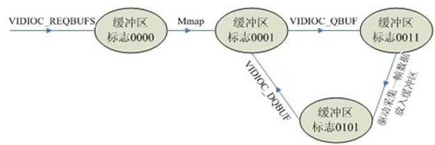
FIG 2 FIG conversion buffer status flag