[Purpose]
1. master role VLAN, TRUNK, VTP and configuration
2 and configuration master role DTP
3 master DHCP relay and the DHCP function and configuration
4 EtherChannel master role and configuration
5 and familiar action DHCPv6 configuration
[lab topology] 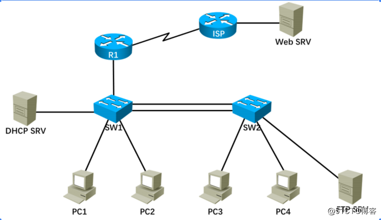
[demand] experiment
- Reference to the illustrated, complete physical topology of structures
- There the campus network 4 one VLAN, respectively VLAN10, VLAN20, VLAN30 and
VLAN40, wherein the DHCP SRV and PC1 in VLAN10 in, PC2, PC3 respectively VLAN20
and VLAN30 in, FTP SRV and PC4 in VLAN40 in which VLAN10 of address segment
addresses 192.168.10.0/24,VLAN20 to address the segment 192.168.20.0/24,VLAN30
address 192.168.30.0/24,VLAN40 segment is 192.168.40.0/24, each VLAN host
gateways are set to its segment available last host address, and set the DHCP service
's IP address 192.168.10.100/24, other hosts to obtain an IP address through DHCP,
outside the campus network planning their own address -
TRUNK using suitable way switch arranged between the link and the standard mode package
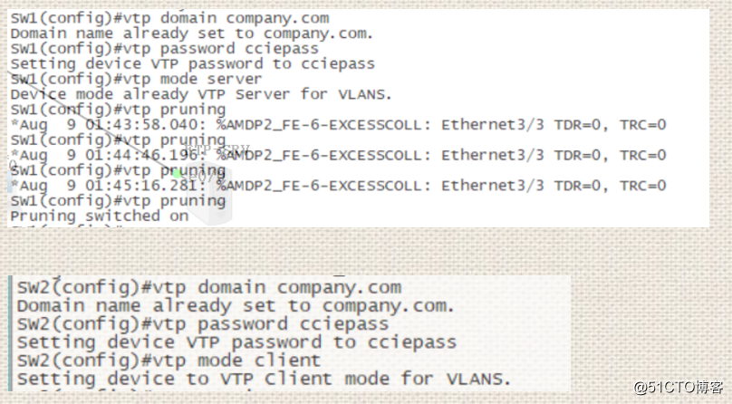
formula - Set SW1 of VTP mode Server, SW2 in VTP mode to Client, and set the VTP
domain name Company.com, password CCIEPASS, to achieve the campus network VLAN information
synchronization - Constructed using standard 802.3ad link between two Ethernet channel switch, the switch requires
EtherChannel load balancing to src-dst-ip -
The requirements on establishing the address pool DHCP SRV, and excludes the range in the respective address pool
around between 10 and 20 from an IP address space and access requirements regardless of when FTP SRV switched
network are acquired 192.168.40.100/ address 24 - Perform other configurations to achieve the hosts and FTP SRV can obtain the corresponding IP address, and
and realize each host can access the Web SRV on ISP
[Experimental Procedure]
Step one:
build a complete topology, the basic configuration of the PC and server.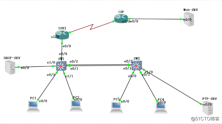
On both switches to create VLAN 10,20,30,40, and PC1 and DHCP-SRV included VLAN10, PC2 included VLAN20, PC3 included VLAN30, PC4 included VLAN40, FTP-SRV included VLAN40.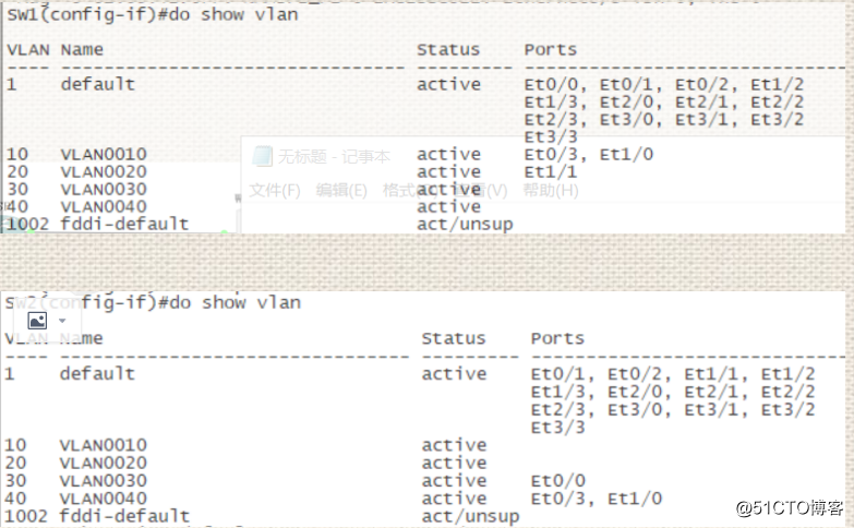
Complete trunk disposed between the switch and standard encapsulation mode.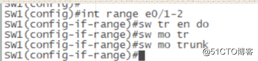
Step two:
Set VTP domain: conpany.com, Password: cciepass
W1 of VTP mode Server, SW2 in VTP mode to Client.
Constructed using standard 802.3ad link between two Ethernet channel switch, the switch requires
EtherChannel load balancing to src-dst-ip
SW2(config-if-range)#channel-group 1 mode active
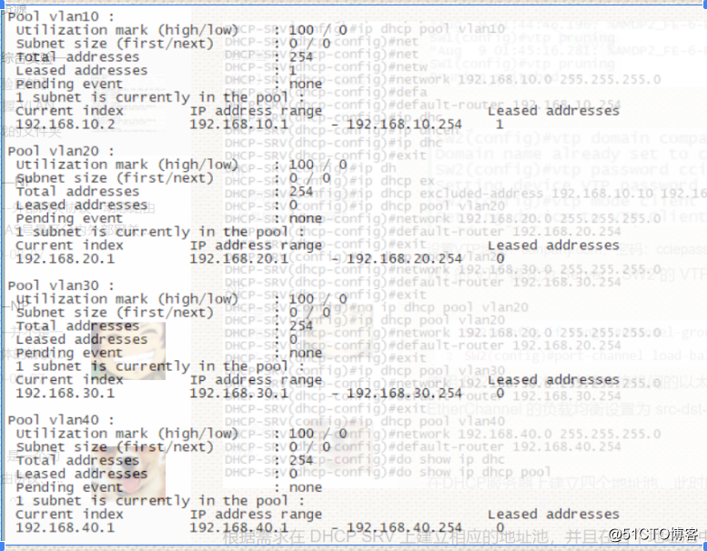
SW2(config)#port-channel load-balance src-dst-ip The establishment of four address pool on the DHCP server, then PC1 has been automatically obtain an IP address.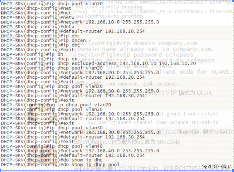

Are arranged on the VLAN10-40S SW1 is on the address which was made when the gateway, thereby acquiring DHCP address to access.
And is provided to help address (enough to be provided with the address of the communication server) so disposed on the server and then have a default route to SW1, PC2 time can obtain the IP address in the int VLAN.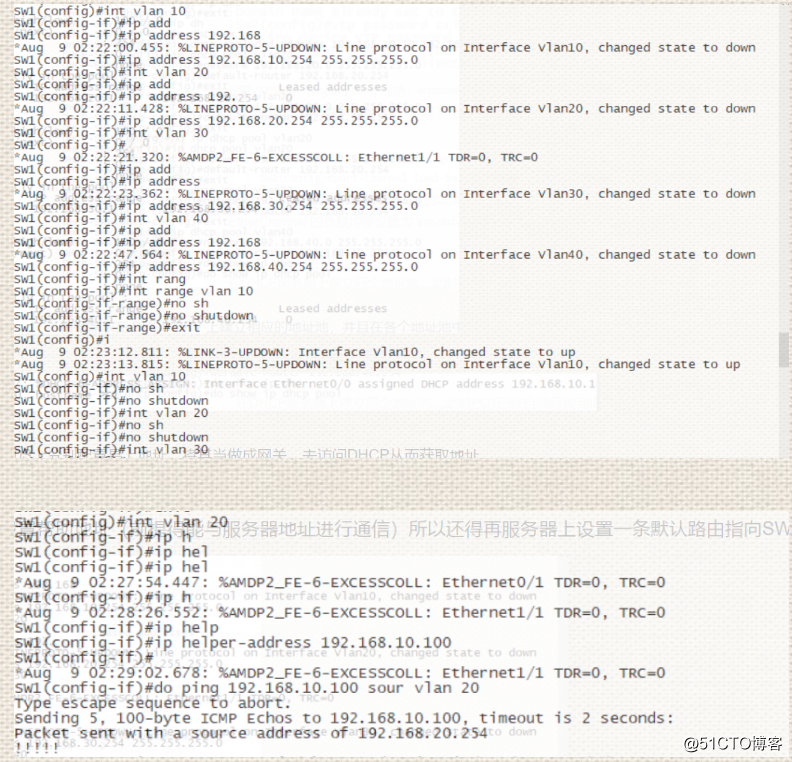
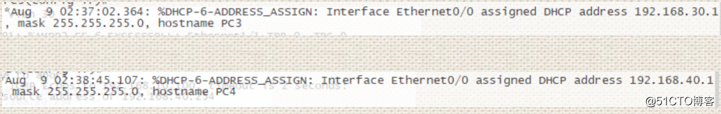
It is also configured to help address int VLAN 30 and 40 int VLAN, this time PC3 and PC4 will be able to get the address.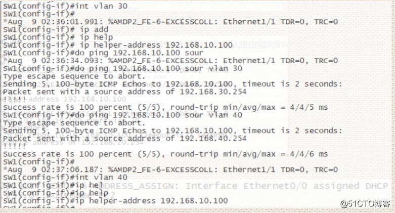
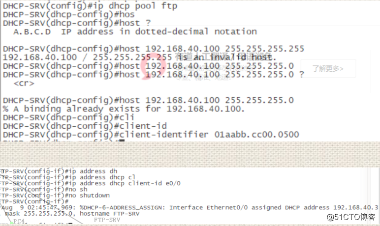
FTP SRV setting when switched access network will obtain the address of 192.168.40.100/24
create a new address pool, and delivers the mode to host.
Perform other configurations to achieve the hosts and FTP SRV can obtain the corresponding IP address, and
and realize each host can access the Web SRV on ISP
R1 in the NAT configuration, and are respectively coupled in the OSPF SW1, SW2 and R1, and R1 on the hair to be configured default route to the outside.
And also configure a default route on an automated issued R1.
Configuration on R1:
IOU1(config)#ip route 0.0.0.0 0.0.0.0 s2/0
IOU1(config)#int s2/0
IOU1(config-if)#ip nat outside
IOU1(config-if)#int e0/0
IOU1(config-if)#ip nat inside
IOU1(config)#access-list 1 permit 192.168.0.0 0.0.255.255
IOU1(config)#ip nat inside source list 1 int s2/0 overload
IOU1(config)#router ospf 1
IOU1(config-router)#network 192.168.0.0 0.0.255.255 area 0
IOU1(config-router)#default-information originate
At this time, the whole network may be a communication has been achieved, through the external network and is able Ping