Show results

I. Overview
The previous blog post explained the use of six cartoon pictures for cube texture mapping to achieve the effect of a rotating box.
This blog post expands on the previous one to achieve the effect of 11 boxes rotating around 7 directional axes.
Why 11 boxes?
Since I only drew 11, you can draw as many as you want.
What are the 7 axes?
The three axes of x, y, and z, as well as the direction axes that form a 45-degree angle between each spatial quadrant and (x, y, z) in the 3-dimensional coordinate system.
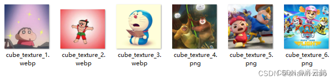
The pictures of the stickers still use the six cartoon pictures in the previous blog post:
2.GLRender: variable definition
2.1 Definition of vertex and texture related variables
In the previous blog post, when I finally called glDrawArrays() for drawing, I used the GL_TRIANGLE_FAN method, which is a way of drawing the vertices in a fan shape with the geometric center of the graphic as the center point, so the previous blog post The definition of the vertex coordinates of each face of the cube is relatively simple.
In this blog post, I will change the implementation of the cube to GL_TRIANGLE_STRIP . The definition of vertex coordinates is in the order of counterclockwise () ()
Vertex coordinate array:
For basic primitives in OpenGL: triangles are drawn in counterclockwise order of vertices .
Therefore, in this article, the vertex coordinates of each face of the cube are defined in the order: (vertex 0, vertex 1, vertex 2) (vertex 2, vertex 3, vertex 0) .

What I want to draw is a cubic box with a side length of 0.5f , so referring to the picture above, change the 1 in the vertex coordinates to 0.5f
public static float[] vertexData = new float[]{

		// back face
		0.5f, 0.5f, -0.5f,
		0.5f, -0.5f, -0.5f,
		-0.5f, -0.5f, -0.5f,
		-0.5f, -0.5f, -0.5f,
		-0.5f, 0.5f, -0.5f,
		0.5f, 0.5f, -0.5f,

		// front face
		-0.5f, 0.5f, 0.5f,
		-0.5f, -0.5f, 0.5f,
		0.5f, -0.5f, 0.5f,
		0.5f, -0.5f, 0.5f,
		0.5f, 0.5f, 0.5f,
		-0.5f, 0.5f, 0.5f,

		// left face
		-0.5f, 0.5f, -0.5f,
		-0.5f, -0.5f, -0.5f,
		-0.5f, -0.5f, 0.5f,
		-0.5f, -0.5f, 0.5f,
		-0.5f, 0.5f, 0.5f,
		-0.5f, 0.5f, -0.5f,

		// right face
		0.5f, 0.5f, 0.5f,
		0.5f, -0.5f, 0.5f,
		0.5f, -0.5f, -0.5f,
		0.5f, -0.5f, -0.5f,
		0.5f, 0.5f, -0.5f,
		0.5f, 0.5f, 0.5f,

		// bottom face
		-0.5f, -0.5f, 0.5f,
		-0.5f, -0.5f, -0.5f,
		0.5f, -0.5f, -0.5f,
		0.5f, -0.5f, -0.5f,
		0.5f, -0.5f, 0.5f,
		-0.5f, -0.5f, 0.5f,

		// top face
		-0.5f, 0.5f, -0.5f,
		-0.5f, 0.5f, 0.5f,
		0.5f, 0.5f, 0.5f,
		0.5f, 0.5f, 0.5f,
		0.5f, 0.5f, -0.5f,
		-0.5f, 0.5f, -0.5f,
};
Texture coordinate array:
On Android devices, the origin of texture coordinates is in the upper left corner, and the texture coordinates in the lower right corner are (1, 1)
According to Android's texture coordinate system, the one-to-one correspondence between texture coordinates and vertex coordinates is defined as follows:
public static float[] textureData = new float[]{
		0.0f, 0.0f,
		0.0f, 1.0f,
		1.0f, 1.0f,
		1.0f, 1.0f,
		1.0f, 0.0f,
		0.0f, 0.0f,

		0.0f, 0.0f,
		0.0f, 1.0f,
		1.0f, 1.0f,
		1.0f, 1.0f,
		1.0f, 0.0f,
		0.0f, 0.0f,

		0.0f, 0.0f,
		0.0f, 1.0f,
		1.0f, 1.0f,
		1.0f, 1.0f,
		1.0f, 0.0f,
		0.0f, 0.0f,

		0.0f, 0.0f,
		0.0f, 1.0f,
		1.0f, 1.0f,
		1.0f, 1.0f,
		1.0f, 0.0f,
		0.0f, 0.0f,

		0.0f, 0.0f,
		0.0f, 1.0f,
		1.0f, 1.0f,
		1.0f, 1.0f,
		1.0f, 0.0f,
		0.0f, 0.0f,

		0.0f, 0.0f,
		0.0f, 1.0f,
		1.0f, 1.0f,
		1.0f, 1.0f,
		1.0f, 0.0f,
		0.0f, 0.0f,
};
TextureId array:
private int[] textureIds;Texture resource array:
public static int[] textureResIds = new int[]{
		R.drawable.cube_texture_1,
		R.drawable.cube_texture_2,
		R.drawable.cube_texture_3,
		R.drawable.cube_texture_4,
		R.drawable.cube_texture_5,
		R.drawable.cube_texture_6
};
Vertex and texture Buffer:
private FloatBuffer vertexBuffer;
private FloatBuffer textureBuffer;
2.2 Other variable definitions
Other regular variables are not much different from those in the previous blog post.
//MVP矩阵
private float[] mMVPMatrix = new float[16];

//shader程序/渲染器
private int shaderProgram;

private int vPosition;
private int aTextureCoord;
//mvp矩阵属性
private int mvpMatrix;
//采样器属性
private int sampler;

//屏幕宽高比率
private float ratio;
3. GLRender: shaders, memory allocation, etc.
3.1 Shader creation, linking, and use
3.2 Shader attribute acquisition and assignment
3.3 Buffer memory allocation
The codes in these parts are basically the same to achieve 2D graphics drawing.
You can refer to the function code in the 2D drawing related blog post in the column:
- createAndLinkProgram()
- getFloatBuffer()
There is detailed code implementation
Don’t show code again
4. GLRender: Multi-texture loading
Pass in Context and texture resource array textureResIds , return the texture ID , and assign it to the texture id array textureIds.
textureIds = TextureUtils.LoadTexture(mContext, textureResIds);//纹理Id根据贴图数量在Api内部创建,加载纹理贴图后返回纹理Id数组
public static int[] LoadTexture(Context context, int[] resIds) {
BitmapFactory.Options options = new BitmapFactory.Options();
options.inScaled = false;
Bitmap[] bitmaps = new Bitmap[resIds.length];
// 生成纹理id
final int[] textureIds = new int[resIds.length];
glGenTextures(resIds.length, textureIds, 0);
for (int i = 0; i < resIds.length; i++) {
bitmaps[i] = BitmapFactory.decodeResource(context.getResources(), resIds[i], options);
// 绑定纹理到OpenGL
glBindTexture(GL_TEXTURE_2D, textureIds[i]);
glTexParameteri(GL_TEXTURE_2D, GL_TEXTURE_MIN_FILTER, GL_LINEAR_MIPMAP_LINEAR);
glTexParameteri(GL_TEXTURE_2D, GL_TEXTURE_MAG_FILTER, GL_LINEAR);
// 加载bitmap到纹理中
GLUtils.texImage2D(GL_TEXTURE_2D, 0, bitmaps[i], 0);
// 生成MIP贴图
glGenerateMipmap(GL_TEXTURE_2D);
// 取消绑定纹理
glBindTexture(GL_TEXTURE_2D, 0);
bitmaps[i].recycle();
}
return textureIds;
}5. GLRender: Drawing
Except for the different methods used for the vertex and texture coordinate arrays, the other parts described above are basically the same as drawing a single box in the previous article.
However, the next part of the drawing is different.
5.1 Seven directional axes
What this blog post wants to achieve is "11 boxes rotate around 7 axes", so we must first define the direction vectors of the 7 axes:
public static float[][] rotate = {
		{1,   1,  1},
		{1,   0,  0},    //X轴
		{-1, -1,  1},
		{0,   1,  0},    //Y轴
		{-1, -1, -1},
		{0,   0,  1},    //Z轴
		{1,  -1, -1},
};
5.2 How to generate eleven boxes?
Define 11 direction vectors to move the box to 11 different positions
public static float[][] directions = {
		{0.0f, 0.0f, -9.0f},
		{0.0f, -2.0f, -6.0f},
		{-1.5f, -4.5f, -9.0f},
		{-1.5f, -2.0f, -5.0f},
		{1.5f, 1.0f, -7.0f},
		{0.0f, 2.0f, -8.0f},
		{-1.5f, 2.0f, -6.0f},
		{-1.5f, 3.7f, -7.0f},
		{2.0f, 4.0f, -8.0f},
		{-1.5f, 0.0f, -5.0f},
		{1.5f, -3.0f, -6.0f},
};
5.3 onDrawFrame()
Each drawing requires drawing 11 boxes, which means moving one box to 11 different positions, so a for() needs to be used to update the mMVPMatrix in a loop.
In this for() loop, we need to texture map the 6 faces of each box, so we need to add a sub- for() loop for texture mapping.
code show as below:
@Override
public void onDrawFrame(GL10 gl) {
	...

	for (int i = 0; i < directions.length; i++) {
		mMVPMatrix = TransformUtils.getCubeTexturesMVPMatrix(i, ratio);
		//设置MVP变换矩阵到着色器程序/渲染器
		glUniformMatrix4fv(mvpMatrix, 1, false, mMVPMatrix, 0);

		int count = 6;
		for (int j = 0; j < textureIds.length; j++) {
			int first = j * count;
			//绑定纹理
			glBindTexture(GL_TEXTURE_2D, textureIds[j]);
			glDrawArrays(GL_TRIANGLE_STRIP, first, count);
		}
	}

	...
}
5.4 getCubeTexturesMVPMatrix()
Code:
private static float mCubeTexturesRotateAgree = 0.0f;

public static float[] getCubeTexturesMVPMatrix(int i, float ratio) {
	//初始化modelMatrix, viewMatrix, projectionMatrix
	float[] modelMatrix = getIdentityMatrix(16, 0); //模型变换矩阵
	float[] viewMatrix = getIdentityMatrix(16, 0); //观测变换矩阵/相机矩阵
	float[] projectionMatrix = getIdentityMatrix(16, 0); //投影变换矩阵

	/*设置透视投影变换矩阵*/
	Matrix.frustumM(projectionMatrix, 0, -ratio, ratio, -1, 1, 3, 25);

	//获取modelMatrix, viewMatrix, projectionMatrix
	//获取观测变换矩阵,设置相机位置
	Matrix.setLookAtM(viewMatrix, 0, 0, 0, 10, 0, 0, 0, 0, 1, 0);
	//设置平移矩阵
	Matrix.translateM(viewMatrix, 0, directions[i][0], directions[i][1], directions[i][2]);

	//获取模型旋转变换矩阵
	int rIndx = i % rotate.length;
	mCubeTexturesRotateAgree = (mCubeTexturesRotateAgree + 1.0f / directions.length) % 360;
	Matrix.rotateM(viewMatrix, 0, mCubeTexturesRotateAgree, rotate[rIndx][0], rotate[rIndx][1], rotate[rIndx][2]);

	//计算MVP变换矩阵: mvpMatrix = projectionMatrix * viewMatrix * modelMatrix
	float[] mvpMatrix = new float[16];
	Matrix.multiplyMM(mvpMatrix, 0, projectionMatrix, 0, viewMatrix, 0);

	return mvpMatrix;
}
6. Shader code
Same as single box drawing, no difference
6.1 cube_texture_vertex_shader.glsl
#version 300 es

layout (location = 0) in vec4 vPosition;
layout (location = 1) in vec2 aTextureCoord;

uniform mat4 mvpMatrix;

out vec2 vTexCoord;

void main() {
    gl_Position = mvpMatrix * vPosition;
    vTexCoord = aTextureCoord;
}
6.2 cube_texture_fragment_shader.glsl
#version 300 es
#extension GL_OES_EGL_image_external_essl3 : require
precision mediump float;

uniform sampler2D sampler;

in vec2 vTexCoord;

out vec4 outColor;

void main(){
    outColor = texture(sampler,vTexCoord);
}
7. Conclusion
This ends the explanation of 11 cartoon boxes rotating around 7 directional axes.
The final effect is shown at the beginning of this blog post