Principles and examples of row and column scanning identification of MCU peripheral matrix keyboard
1 Overview
This article introduces the microcontroller to identify the keys of the matrix keyboard through row and column scanning, and perform the corresponding operations through the program.
2.Principle of row and column scanning recognition
2.1.Principle of independent key recognition
Why do we need matrix keys?
Independent keys are simple to operate. When the number is large, they will occupy the IO port of the microcontroller, limiting the number of keys and unable to meet scenarios that require more keys. Therefore, the matrix keyboard was born. It has a large number of keys. There are very few IO ports occupied.
Why introduce independent keys
? Why not directly introduce matrix keys but first introduce the working principle of independent keys? This is because the matrix keyboard is an upgrade in the number of independent keys. The working principle of the matrix keyboard has not changed, it is still the working principle of independent keys.
How an independent button works
- When we connect the buttons to the microcontroller, we can control the LED lights to turn on and off through the buttons.
- - Its working principle is to connect one end of the button to the IO port of the microcontroller and the other end to the GND end.
- When the button is pressed, the IO port connected to the button and GND are connected, and the high level becomes low level.
- When it is detected that the IO port is low level, the LED light is turned on.
- Release the button and the IO port returns to high level, causing the LED light to turn off.
Working Principle of Multiple Independent Buttons
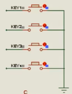
Once we have mastered the principle of an independent button controlling LED lights, we can connect multiple independent buttons in parallel with a wire and connect it to GND, and the other end of the button is connected to each IO port of the microcontroller to form A row of independent keys.
- Define the name of each button connected to the IO port of the microcontroller
- When a button is pressed, the corresponding IO port pin will be connected to GND, and the high level will change to low level.
- Detect the button corresponding to the low-level pin, and then perform the corresponding operation through program logic.
2.2. Independent button upgrade matrix button
When one column of independent keys is not enough, multiple columns can be added. However, the IO port of the microcontroller is limited, so more buttons cannot be inserted. At this time, matrix wiring can be used to connect multiple columns of independent keys to form a matrix keyboard in rows and columns.
The working principle of row and column scanning
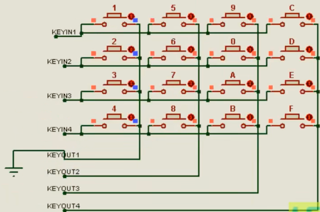
. For example, the picture below shows a 4X4 matrix keyboard, KEYIN1~KEYIN4with rows and KEYOUT1~KEYOUT4columns.
- Row scanning of the first column: If we connect the first column to GND
KEYIN1~KEYIN4and the row to the 4 IO ports of the microcontroller, then the multiple independent buttons above form a column of independent button scenes. When a button is pressed, the first column will be scanned. The high and low levels of the keys in rows 1 to 4 of a column. - Second column row scanning: Connect the second column to GND,
KEYIN1~KEYIN4and connect the rows to the 4 IO ports of the microcontroller. When a button is pressed, the high and low levels of rows 1 to 4 of the second column will be scanned. - Row scanning of the third column: Connect the third column to GND,
KEYIN1~KEYIN4and connect the rows to the 4 IO ports of the microcontroller. When a button is pressed, the high and low levels of rows 1 to 4 of the third column will be scanned. - Fourth column row scanning: Connect the third column to GND,
KEYIN1~KEYIN4and connect the rows to the 4 IO ports of the microcontroller. When a button is pressed, the high and low levels of rows 1 to 4 of the fourth column will be scanned.
Implementation Principle of Row and Row Scanning Software
After understanding the working principle of row and row scanning of matrix keyboard, you can use a program to realize row and row scanning to identify keys.
- Scan the first column: Connect the first column
KEYOUT1to the pin of the microcontroller and set it to low level, then you can simulate the hardware circuit and connect it to GND.KEYIN1~KEYIN4Connect the row to the 4 IO ports of the microcontroller and set it to high level. When pressed,1号按键then The first row is connected to the first column, and the high level of the first row becomes low level. At this time, the press can be recognized1号按键. - Scan the second column:
KEYOUT2Connect the second column to the pin of the microcontroller and set it to low level.KEYIN1~KEYIN4Connect the row to the 4 IO ports of the microcontroller and set it to high level. When pressed,5号按键the first row will be connected to the second column. If it passes, the high level of the first line will change to low level, and at this time, the press can be recognized5号按键. - Scan the third column:
KEYOUT3Connect the third column to the pin of the microcontroller and set it to low level.KEYIN1~KEYIN4Connect the row to the 4 IO ports of the microcontroller and set it to high level. When pressed,9号按键the first row will be connected to the third column. If it passes, the high level of the first line will change to low level, and at this time, the press can be recognized9号按键. - Scan the fourth column:
KEYOUT4Connect the fourth column to the pin of the microcontroller and set it to low level.KEYIN1~KEYIN4Connect the row to the four IO ports of the microcontroller and set it to high level. When pressed,C号按键the first row will be connected to the fourth column. If it passes, the high level of the first line will change to low level, and at this time, the press can be recognizedC号按键.
3. Row and column scanning example
According to the matrix keyboard's row and column scanning principle, a program is used to identify the keys and perform corresponding operations.
/*
程序名:行列扫描操作矩阵键盘
编写人:bruce
编写时间:2023年12月
硬件支持:STC12C2052AD系列
接口说明:
修改日志:
  NO.1-
*/

#include <STC12C2052AD.H> //STC12Cx052或STC12Cx052AD系列单片机头文件
// 定义LED灯
sbit LED = P3^7;
// 定义行扫描按键
sbit KEYIN1 = P1^0;
sbit KEYIN2 = P1^1;
sbit KEYIN3 = P1^2;
sbit KEYIN4 = P1^3;

//定义列扫描按键
sbit KEYOUT1 = P1^4;
sbit KEYOUT2 = P1^5;
sbit KEYOUT3 = P1^6;
sbit KEYOUT4 = P1^7;

/*
函数名:毫秒级CPU延时函数
调  用:DELAY_MS (?);
参  数:1~65535(参数不可为0)
返回值:无
结  果:占用CPU方式延时与参数数值相同的毫秒时间
备  注:应用于1T单片机时i<600,应用于12T单片机时i<125
*/
void DELAY_MS (unsigned int a){


	unsigned int i;
	while( a-- != 0){


		for(i = 0; i < 600; i++);
	}
}


/*
作用:行列扫描方式识别矩阵键盘按键
参数:返回识别到的按键
返回:
*/
unsigned char keyScan(){


	unsigned char keyNum;
	/*
		扫描第一列行上面的按键
	*/
	KEYIN1,KEYIN2,KEYIN3,KEYIN4 = 1;
	KEYOUT2,KEYOUT3,KEYOUT4 = 1;
	// 第一列设置为低电平
	KEYOUT1 = 0;
	if(!KEYIN1 || !KEYIN2 || !KEYIN3 || !KEYIN4 ){


		DELAY_MS(20);
		if(!KEYIN1 || !KEYIN2 || !KEYIN3 || !KEYIN4){


			if(!KEYIN1){


				keyNum = 1;
			}
			if(!KEYIN2){


				keyNum = 2;
			}
			if(!KEYIN3){


				keyNum = 3;
			}
			if(!KEYIN4){


				keyNum = 4;
			}
		}
		//等待按键松开
		while(!KEYIN1 || !KEYIN2 || !KEYIN3 || !KEYIN4);
	}

	/*
		扫描第二列行上面的按键
	*/
	KEYIN1,KEYIN2,KEYIN3,KEYIN4 = 1;
	KEYOUT1,KEYOUT3,KEYOUT4 = 1;
	// 第二列设置为低电平
	KEYOUT2 = 0;
	if(!KEYIN1 || !KEYIN2 || !KEYIN3 || !KEYIN4 ){


		DELAY_MS(20);
		if(!KEYIN1 || !KEYIN2 || !KEYIN3 || !KEYIN4){


			if(!KEYIN1){


				keyNum = 5;
			}
			if(!KEYIN2){


				keyNum = 6;
			}
			if(!KEYIN3){


				keyNum = 7;
			}
			if(!KEYIN4){


				keyNum = 8;
			}
		}
		//等待按键松开
		while(!KEYIN1 || !KEYIN2 || !KEYIN3 || !KEYIN4);
	}

	/*
		扫描第三列行上面的按键
	*/
	KEYIN1,KEYIN2,KEYIN3,KEYIN4 = 1;
	KEYOUT1,KEYOUT2,KEYOUT4 = 1;
	// 第三列设置为低电平
	KEYOUT3 = 0;
	if(!KEYIN1 || !KEYIN2 || !KEYIN3 || !KEYIN4 ){


		DELAY_MS(20);
		if(!KEYIN1 || !KEYIN2 || !KEYIN3 || !KEYIN4){


			if(!KEYIN1){


				keyNum = 9;
			}
			if(!KEYIN2){


				keyNum = 10;
			}
			if(!KEYIN3){


				keyNum = 11;
			}
			if(!KEYIN4){


				keyNum = 12;
			}
		}
		//等待按键松开
		while(!KEYIN1 || !KEYIN2 || !KEYIN3 || !KEYIN4);
	}

	/*
		扫描第四列行上面的按键
	*/
	KEYIN1,KEYIN2,KEYIN3,KEYIN4 = 1;
	KEYOUT1,KEYOUT2,KEYOUT3 = 1;
	// 第四列设置为低电平
	KEYOUT4 = 0;
	if(!KEYIN1 || !KEYIN2 || !KEYIN3 || !KEYIN4 ){


		DELAY_MS(20);
		if(!KEYIN1 || !KEYIN2 || !KEYIN3 || !KEYIN4){


			if(!KEYIN1){


				keyNum = 13;
			}
			if(!KEYIN2){


				keyNum = 14;
			}
			if(!KEYIN3){


				keyNum = 15;
			}
			if(!KEYIN4){


				keyNum = 16;
			}
		}
		//等待按键松开
		while(!KEYIN1 || !KEYIN2 || !KEYIN3 || !KEYIN4);
	}
	return keyNum;

}

void main(){


	while(1){


		switch(keyScan()){


			case 1:
				LED = 0;
				break;
			case 2:
				LED = 1;
				break;
			default:
				LED =1;
		}
	}

}