Table of contents
BKP is essentially a RAM register and cannot be completely lost without losing power. Its data requires backup power provided by the VBAT pin to maintain it. RTC reset and power loss are achieved through BKP.
Unix timestamp
Introduction

timing standards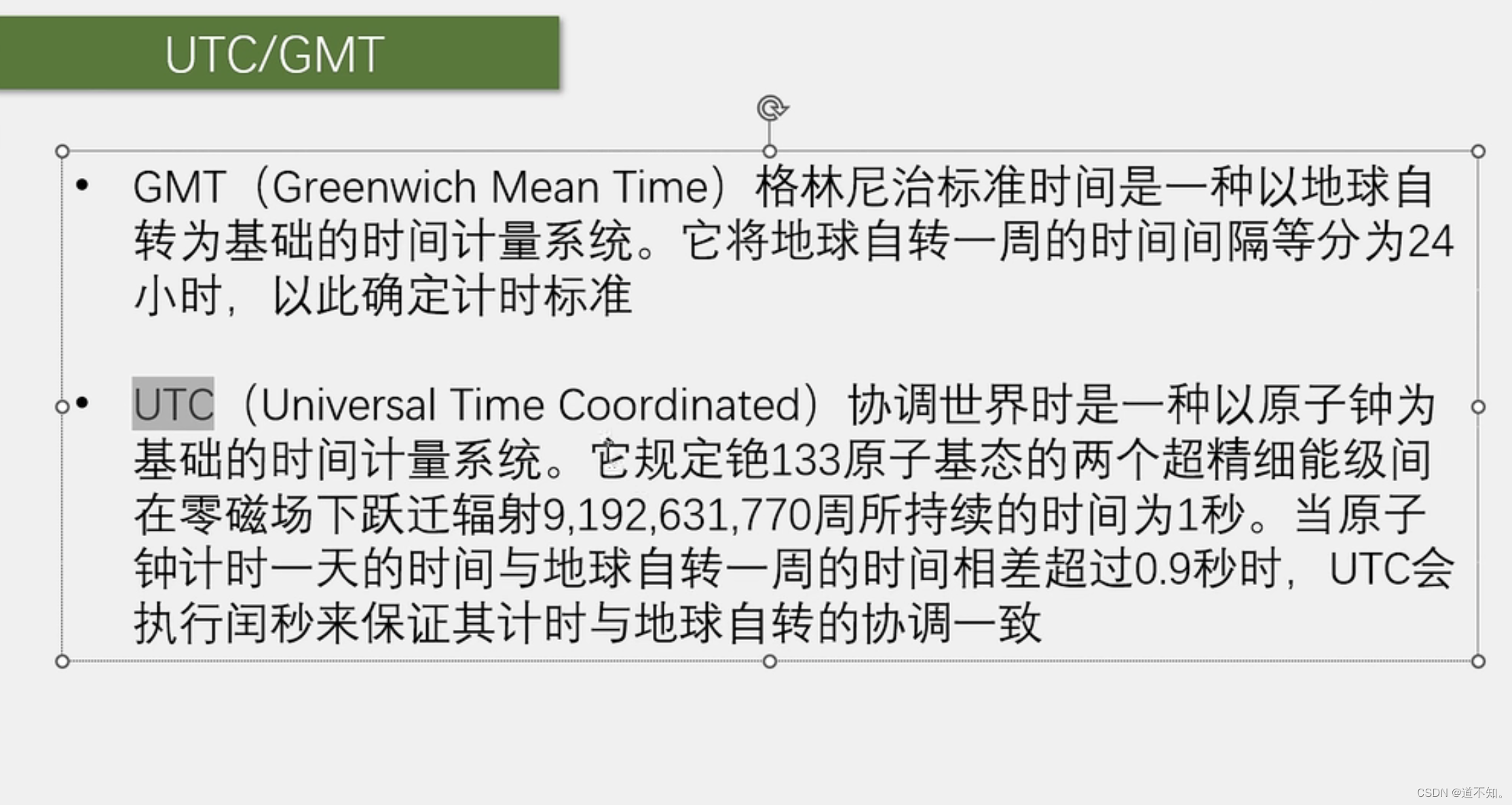
timestamp conversion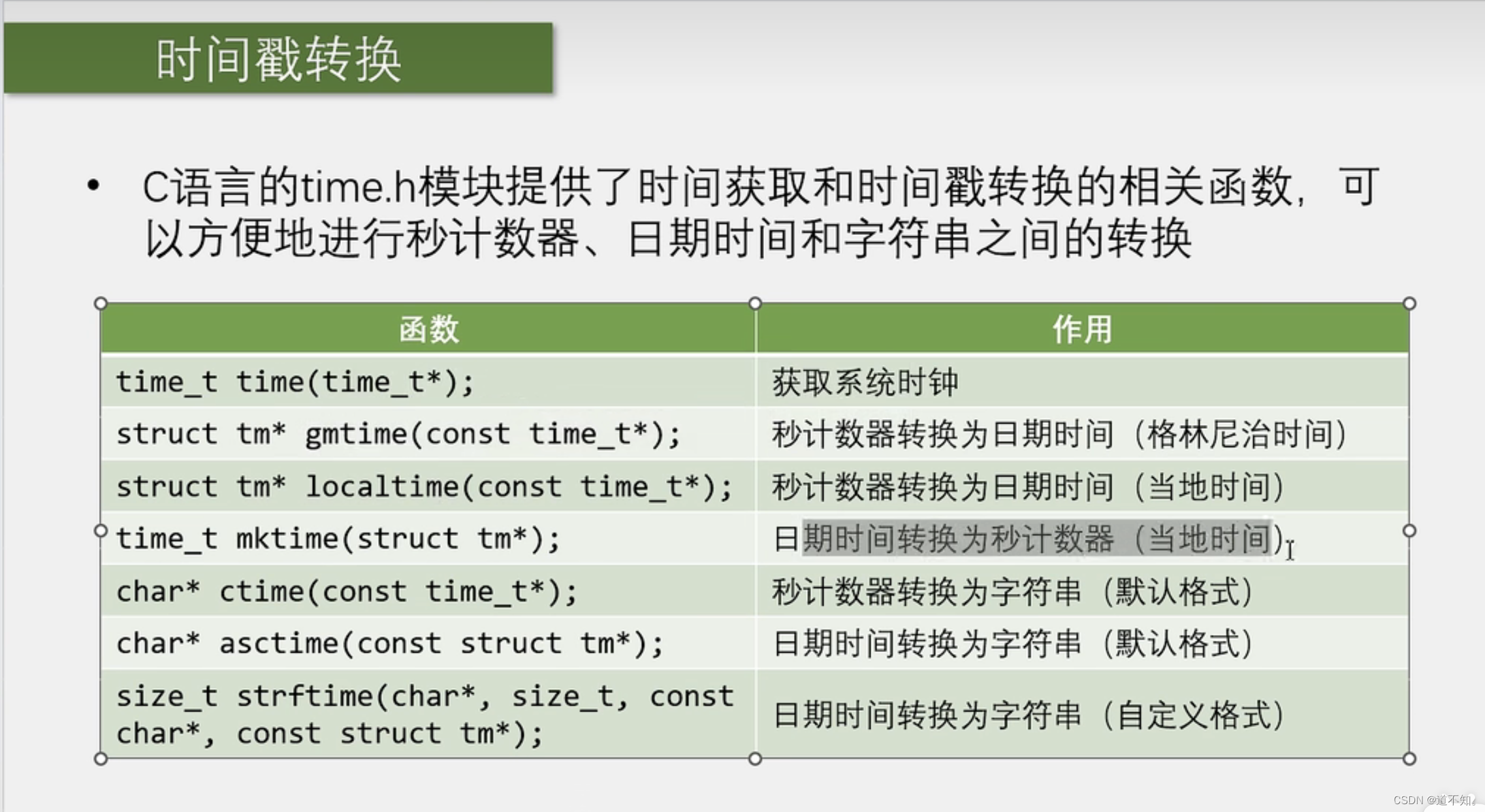

Sample code
#include <stdio.h>
#include <stdlib.h>
#include <time.h>

time_t time_cnt;
struct tm time_date;
char *str;
int main()
{
    //调用 time_t time(time_t*)获取系统时钟;
    time_cnt=time(NULL);        //方法一
    time(&time_cnt);            //方法二
    printf("%d\n",time_cnt);

    //调用struct tm* gmtime(const time_t*)秒计数器转换伦敦时间(格林尼治时间)的函数
    time_date=* gmtime(&time_cnt);  //方法一对右边取内容
   // time_date=gmtime(&time_cnt);  //方法二将左边定义为指针类型。struct tm *
    printf("%d ",time_date.tm_year+1900);
    printf("%d ",time_date.tm_mon+1);
    printf("%d ",time_date.tm_mday);
    printf("%d ",time_date.tm_hour);
    printf("%d ",time_date.tm_min);
    printf("%d ",time_date.tm_sec);
    printf("%d \n",time_date.tm_wday);


    // 调用struct tm* localtime(const time_t*)秒计数器转换为日期时间(当地时间)
    time_date=* localtime(&time_cnt);  //方法一对右边取内容
    printf("%d ",time_date.tm_year+1900);
    printf("%d ",time_date.tm_mon+1);
    printf("%d ",time_date.tm_mday);
    printf("%d ",time_date.tm_hour);
    printf("%d ",time_date.tm_min);
    printf("%d ",time_date.tm_sec);
    printf("%d \n",time_date.tm_wday);

    //time_t mktime(struct tm*)  日期时间转换为秒计数器(当地时间)
    time_cnt=mktime(&time_date);
    printf("%d\n",time_cnt);

    //char* ctime(const time_t*)  秒计数器转化为字符串(默认格式)
    str=ctime(&time_cnt);
    printf(str);

    //char *asctime(const struct tm*)   日期时间转换为字符串(默认格式)
   str = asctime(&time_date);
   printf(str);

   //size_t strftime(char*,size_t,const char*,connst struct tm*)  日期时间转换为字符串(自定义格式)
    char a[50];
    strftime(a, 50, "%H-%M-%S",&time_date);
    printf(a);

    return 0;
}
operation result

BKP
Introduction

BKP basic structure

RTC
Introduction to RTC

RTC block diagram
- The gray area is the backup area, these circuits can use backup batteries to maintain operation after the main power supply is lost.
- The RTC_CNT 32-bit programmable counter corresponds to the seconds counter in the timestamp. When reading the time, first get the seconds and then call the localtime function in time.h to get the year, month, day, hour, minute and second information. When writing time, first fill in the year, month, day, hour, minute and second information into the struct tm structure, and then use maketime to get the number of seconds and write it to the 32-bit counter.
- RTC_RPL reload counter, RTC_DIV remainder decrement counter. Every time an input clock comes, RTC_DIV decrements by one. When it reaches 0, another input clock comes and outputs a pulse, generating an overflow signal and obtaining the reload value at the same time.
- RTC_ALP alarm register. When CNT is the same as the set alarm value, an RTC_Alarm signal will be generated, leading to the interrupt system on the right. At the same time, this alarm signal can allow stm32 to exit standby mode (which can have some uses). The alarm clock value is a fixed value that can only sound once, so to implement a periodic alarm clock, you need to reset the next alarm clock time after the alarm clock sounds.
- RTCCLK three sources, see the next picture

In the RCC clock tree, only the middle clock dedicated to RTC can be powered by the VBAT backup battery (which can realize the function of continuing to run when the RTC main power supply is cut off). The upper and lower clocks stop running when the main power supply is cut off.
RTC basic structure
Configuring the data selector can select the clock source
Configuring the reload register can select the frequency division coefficient
Configure a 32-bit counter to read and write date and time
Alarm clock can be realized by configuring 32-bit alarm clock value
To implement interrupts, first allow the terminal, then configure the NVIC and finally write the interrupt function.

Hardware circuit
The black part is a 32.768khz crystal oscillator, and the metal shell is an 8khz external high-speed crystal oscillator.
You can refer to the picture below to connect the drawing board.

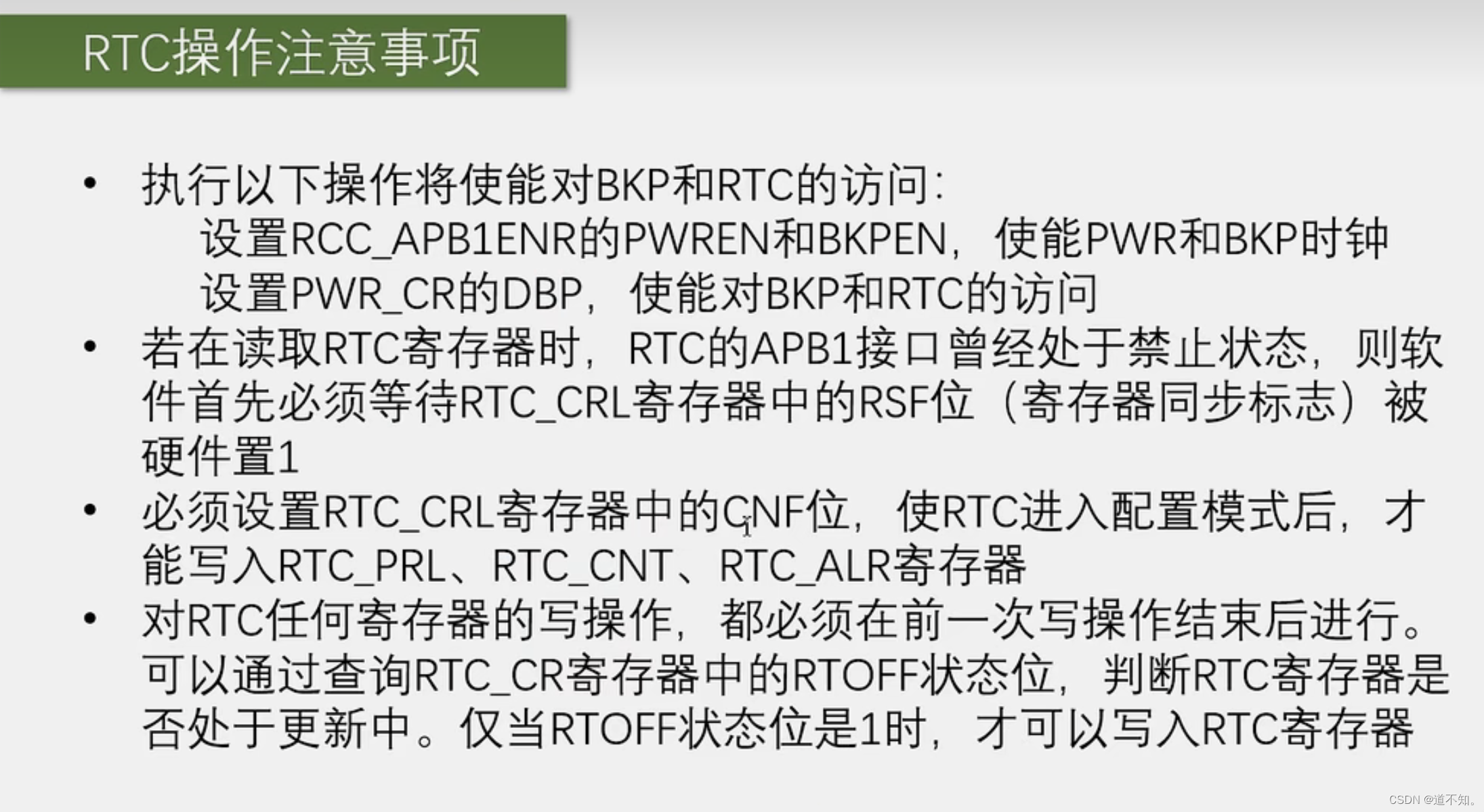
Precautions for RTC operation
The first step is to turn on the clocks of PWR and BKP. The second step is to use PWR and enable BKP and RTC access.
It can be seen in the block diagram that the frequency of PCLK132MHZ is much larger than RTCCLK32KHZ. Therefore, when you first turn on APB1, you have to wait for RTCCLK, and a rising edge of RTC synchronizes its register value to the APB1 bus. Just call a function that waits for synchronization.