The previous article talked about the architecture and application scenarios of the audio system on smart watches. Let’s start with the specifics in this article. First, let’s talk about audio-related drivers, which mainly include IPC (inter-processor communication, inter-core communication, that is, communication between AP/CP/ADSP) drivers and audio drivers. First of all, let me explain that since the codec is designed by our company and is built into the SOC, and the driver is on ADSP (ADSP uses RTOS), the driver code will not be as universal as Linux ALSA.
Before talking about the driver, let's first look at what interrupts and memories are used. The interrupts used mainly include IPC interrupts and ADMA (Audio DMA) interrupts. IPC is essentially interrupt plus Ring Buffer. When using the built-in codec and Bluetooth calls, the system is driven by ADMA interrupts (this interrupt comes at equal intervals), that is, equally spaced ADMA interrupts drive the audio system, which will be discussed in detail later. There are mainly 5 pieces of memory used, as follows: 1. ITCM (in-chip, code). 2. DTCM (on-chip, data placement). 3. The shared memory used for data interaction between ADSP and other cores. This memory is on SRAM. It must be accessible to both parties doing data interaction, and both parties must be set to uncacheable. 4. The memory that stores the audio data collected by the codec. This memory ASIC is designed specifically for audio. The latency for audio is very small, and there will be no other competition that will cause audio to be stuck. 5. The memory used for audio in DDR is off-chip and is allocated to audio during design. It can contain both code and data. Parts of it can be set to cacheable or uncacheable as needed. The following figure shows which memories should be set as cacheable and which should be set as uncacheable:

1, IPC driver
IPC is inter-core communication (communication between AP/CP/ADSP), that is, data exchange between cores. To interact with data, you must first define the data format so that both parties can parse it. Interaction data includes control data (such as enabling a stream) and audio data. As mentioned above, IPC is essentially interrupt plus Ring Buffer (since it is a Ring Buffer, it must have a read and write index). The Ring Buffer and its control variables (read and write index, etc.) are all in shared memory that can be accessed by both cores to communicate (the third type of memory mentioned above). If the communication between cores is one-way, only one Ring Buffer is needed. If it is two-way communication, two Ring Buffers are needed. The following figure gives a schematic diagram of a common two-way interaction:

The sender groups the data according to the prescribed format and places it at the beginning of the write index in the Ring Buffer, updates the write index at the same time, and then sends an interrupt to the receiver. After receiving the interrupt, the receiver enters the interrupt service routine, fetches data of the specified size from the beginning of the read index in the Ring Buffer, updates the read index at the same time, and then parses the received data to perform the next step.
The AP and ADSP exchange control commands and audio data in the above manner. In addition, IPC also has functions including outputting the ADSP log to UART and sending the audio data to be dumped from ADSP to the AP and saving it as a file. Since the ADSP log cannot be output directly, the log needs to be sent to the AP through IPC, and the AP then outputs it to UART, etc. Dumping audio data is a very important means for audio debugging. There is no way to dump directly on ADSP. It can only be sent to the AP through IPC and saved as a file. When adjusting the driver, the first thing to adjust is the IPC between the AP and ADSP. Make sure that the communication between the AP and ADSP is normal, the log output of ADSP is normal, and the audio data can be dumped normally. After the IPC is good, adjust other things. A common mistake that novices make when adjusting IPC is not setting the used shared memory to uncacheable, which results in sometimes correct communication and sometimes incorrect communication. As a result, it takes a lot of time to investigate. Experienced people will probably know the reason by looking at the phenomenon. .
ADSP and CP only exchange voice data (only used during voice calls, voice control commands are related to the interaction between ADSP and AP), so the IPC is simplified and uses a fixed buffer (this buffer It is also on a shared memory that both parties can access) instead of Ring Buffer, and only uses one interrupt (ADSP sends an interrupt to CP). The diagram is as follows:
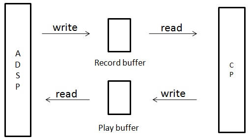
As mentioned above, the system is driven by ADMA interrupts during voice calls. Usually there is an ADMA interrupt every 10ms, and this interrupt drives the audio system to start. In a loop, ADSP first takes the voice data put in by CP to be played from the Play buffer in the above figure, and then takes the collected voice data from the ADSP audio buffer. The collected voice data is processed (such as resampling ) and then send it to the Record Buffer in the picture above, and finally send an IPC interrupt to the CP. After CP receives the interrupt, it first takes out the collected data from the Record buffer and processes it, and then puts the data to be played into the Play buffer.
2, audio driver
The following picture is the hardware block diagram in the previous architecture (Audio on smart watches (1): Architecture):Audio on smart watches (1): Architecture a>

From the picture above, we can see that there are differences in the audio driver when using the built-in codec and BT. The following is divided into two cases.
2.1 Built-in codec
The following figure is the driver hardware block diagram under the built-in codec:

As can be seen from the picture above, the driver mainly consists of two parts, the built-in codec and ADMA (audio DMA). Let’s look at the built-in codec first. The built-in codec can be divided into an analog part (analog, including ADC and DAC) and a digital part (digital, DFE (digital front-end, digital front-end)). The driver of the built-in codec is mainly the configuration register: including configuring the audio clock, DFE, ADC, DAC, etc. Let’s look at ADMA related things. Since it is DMA, it must have a descriptor. The following figure is its structure definition:

byte_counts refers to the size of the ADMA buffer. Once this value is set, the interval for ADMA interrupts is set. For example, the condition for generating an ADMA interrupt is that the ADMA buffer is empty. When the ADMA buffer is empty, an interrupt is generated. The size of the ADMA buffer is usually measured in milliseconds (so you can know how many milliseconds the ADMA interrupt interval is). Knowing the sampling rate and the number of channels, you can calculate the number of bytes. Assuming ADMA buffer 10ms, 48K samples, two channels, the size of ADMA buffer is 1920bytes (10*48*4 = 1920), so once the size of ADMA buffer is determined, the interval of ADMA interrupt is also determined. Src_addr is the original address, dst_addr is the destination address, and the audio data will be moved from the original address to the destination address. In the collection direction, src_addr is the hardware address, and dst_addr is the address of the audio buffer in adsp. In the playback direction, src_addr is the hardware address of the audio buffer in adsp, and dst_addr is the hardware address. next_desc points to the next descriptor. There are usually two descriptors in one direction, and the two descriptors point to each other. The ADMA driver mainly includes hang-up interrupts, register configuration (the contents in the descriptor above and interrupt generation conditions, etc.) and the handling of audio data. In the collection direction, the audio data is mainly moved from the hardware address to the audio buffer of adsp. In the playback direction, the audio data is mainly moved from the audio buffer of adsp to the hardware address. ADSP's audio buffer can use two different blocks or the same block in the two directions. When using two blocks, two ADMA interrupts (one in each direction) are required, and accordingly there are two interrupt service routines. Because the two directions are unrelated, the processing is relatively simple. The disadvantage is that memory is wasted (memory on ADSP is very precious). When using one block, only one ADMA interrupt is needed. Because the two directions are related, the processing is more complicated (if the processing is not good, it will cause data stampede). The advantage is that it saves memory.
2.2 Bluetooth
The following figure is the driver hardware block diagram under Bluetooth:
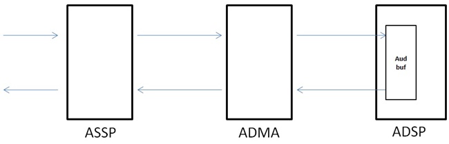
As can be seen from the above figure, the driver mainly consists of two parts, ASSP (audio SSP (Synchronous Serial Port, synchronous serial interface)) and ADMA. ADMA is the same as the built-in codec, so I won’t go into detail here. To put it bluntly, ASSP is to configure whether it is a PCM bus or an I2S bus. The configuration content includes the data length of audio sampling, sampling mode (rising edge sampling or falling edge sampling), alignment mode (left-aligned or right-aligned), frame synchronization width, etc.
Regardless of the above two cases, the first thing to ensure is that after configuring the registers, the ADMA interrupt must wait for a regular time (such as 10ms). If it does not mean that there is a problem with the register configuration, you need to read the datasheet carefully to understand. Configuration means. You can add a log in the ISR (interrupt service routine). If the log appears at regular intervals, it basically means that ADMA interrupts are coming at regular intervals.
First adjust the audio driver under the built-in codec. After the interruption is normal, adjust the playback direction first. Write a sine wave into the ADSP audio buffer. If a tone sound is emitted from the speaker, it means that the playback direction has been adjusted upward. Then adjust the acquisition direction. Send the data collected in the ADSP audio buffer to the AP through IPC and save it as a file. Use audio software (such as CoolEdit) to listen. If it matches what you say to the mic, it means the adjustment is done. Since hardware is involved, the debugging process requires the support of ASIC, analog and hardware related personnel, such as whether the registers are paired, whether a certain PIN output meets expectations, etc. After all, they are more experienced in hardware. The driver under BT is only used for Bluetooth voice calls. It is easier to adjust the driver under BT after adjusting the voice call under the built-in codec, because the entire link only needs to change the driver under the built-in codec to BT. It is easier to verify whether the driver is adjusted correctly. Compared with the built-in codec, the driver under BT has some value modifications such as ADMA, mainly adjusting ASSP. After ASSP configures the registers, use an oscilloscope to measure the signals (SCLK/SYNC/DIN/DOUOT, etc.), and it should be as expected. Finally, I used Bluetooth to make calls. If the sound in both the sending and receiving directions is normal, it means the adjustment is done.
The audio driver is equivalent to the foundation. After the foundation is completed, we start building the building (developing specific functions). Let’s start with the specific functions in the next article, starting with audio file playback.