Table of contents
- Preface
- 1. A brief understanding of the AHT20 module (in order to better understand the program statements)
- 2. Understand the DMA related interrupt flag bits and the corresponding DMA channel of I2C
- 3. This article mentions the relevant variable definitions in the program to understand in advance.
- 4. Understand in advance the DMA+IIC data sending and receiving process and the related functions in the program used in this article
- 5. Experiment 1 Use IIC+DMA to complete the process of data transmission
- 6. Experiment 2: Use IIC+DMA to complete the data reception process
- 7. Experiment 3: Use IIC+DMA to complete the process of data sending and data receiving
- 8. Conclusion
Preface
In the past few days, I have been studying IIC communication to read and write data. After learning about software IIC implementation and hardware IIC implementation of I2C communication, I found that both software I2C and hardware I2C take up more CPU resources. Although hardware IIC does not need to be like software IIC also needs to rely on the program to continuously pull the SCL and SDA pins high and low, but the hardware IIC still requires the CPU to continuously run relevant instructions to achieve complete IIC functions. To deal with this drawback, using the CPU assistant - DMA in conjunction with I2C can greatly reduce the burden on the CPU.
For me, in order to learn this content, I struggled on the Internet for several days. To be honest, I didn’t find many articles that were of substantial help to me, because my purpose was In order to use the STM32 standard library to complete this work, but what appears on the Internet more often is the HAL library version and the LL library version of the IIC+DMA hardware read When writing a program, because the HAL library is relatively complete and does not require users to understand it as thoroughly as the standard library, I only saw it in the clouds and mist, and I just didn’t understand it anyway. After repeated struggles, I finally achieved the desired effect. I wrote this article mainly to leave a record and notes for myself so that I can refer to it later. It would be best if this article can help everyone at the same time. Because most of the work is done by myself, this article may have many wrong descriptions and places. If you see any mistakes, you can send a private message or comment and I will correct them as soon as possible. Thank you.
What does this article aim to achieve? The main implementation content of this article is to use IIC+DMA (STM32 standard library) to send AC commands (that is, start measurement commands) to the AHT20 temperature and humidity sensor and obtain the measurement results of the AHT20 sensor. program. What this article wants to show is the DMA combined with hardware IIC method, that is, how to use hardware IIC and DMA to complete data transmission, data reception and how to use it After DMA and I2C complete the data transmission, DMA is used to cooperate with IIC to complete data reception. Therefore, the program in this article is not complete for the AHT20 module. That is, in the program designed in this article, sensor calibration, soft reset, etc. are not set. operation (without these operations, there may be cases where the AHT20 module cannot be used or correct sensor data cannot be obtained), but the main functions of the AHT20 have been implemented, so you can know it.
What knowledge do you need to know in advance to study the content of this article? To learn these things, you need to understand the working process of hardware IIC to a certain extent and understand the working mechanism of DMA. You also need to know some knowledge about interrupts. If you can independently complete programs that use hardware IIC to read and write data and write other DMA data transfer programs before studying this article, then you will have a much easier time in this article.
1. A brief understanding of the AHT20 module (in order to better understand the program statements)
This part of the content is mainly to let everyone know what some of the instructions I sent in the program mean, so that you will not be confused when reading the code. If you understand this module, you can skip it directly.
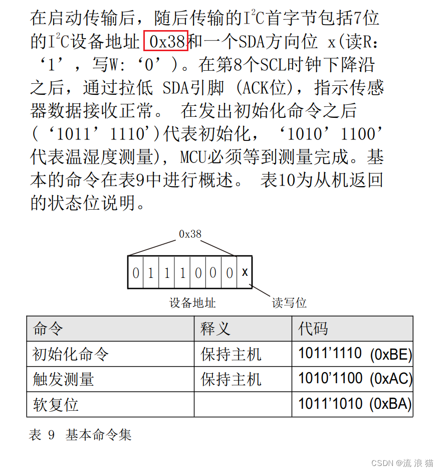
For this part, everyone briefly understands the device address of AHT20, what are the instructions that need to control AHT20 to start measurement, and the measured data will be returned in the form of several bytes, each byte It corresponds to what it means (that is, whether it is a byte representing status, or a byte representing temperature and humidity).
The device address of AHT20 is 0x38. In the following program, I will define it as AHT20_ADDRESS
#define AHT20_ADDRESS (0x38 << 1) // AHT20设备地址
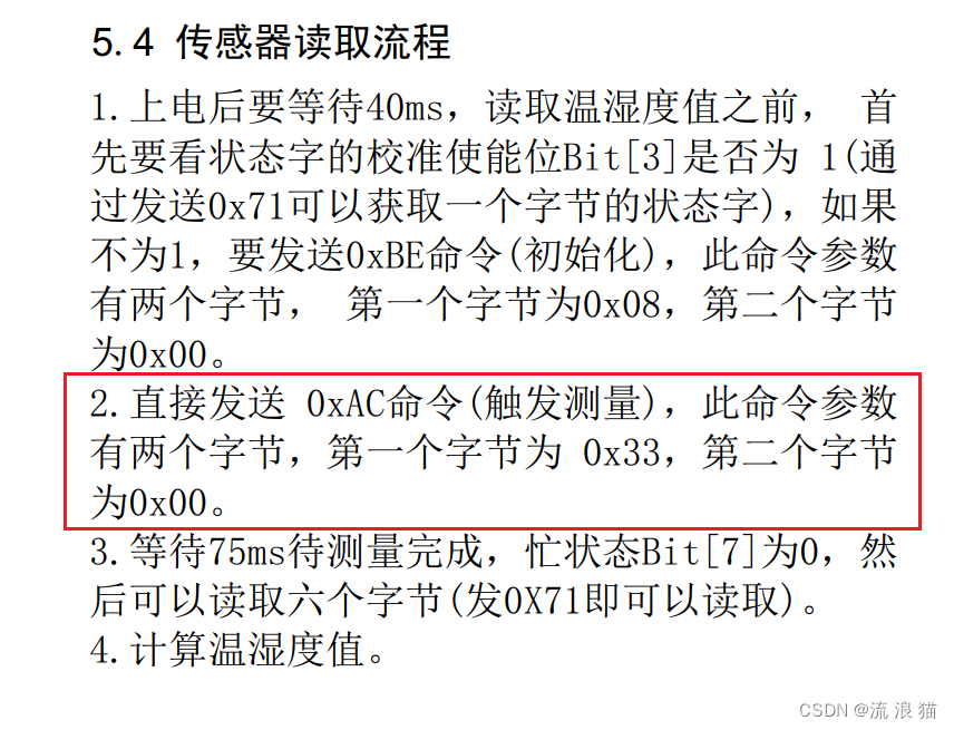
Because this article does not initialize the AHT20, it only sends the start measurement command and receives the data. For the command to be sent, we put it in the array (sending the start measurement requires sending three bytes of data continuously, which are 0xAC , 0x33, 0x00), when the time comes, the DMA will send it to the DR register of I2C1, and the hardware will automatically send it to the peripheral. (In addition, the program does not judge the Bit[7] status bit mentioned in No. 3 in the figure below, so the program is not rigorous and everyone will improve it later.)
static uint8_t AC[3] = {

    0xAC,0x33,0x00};  // AHT20开始测量指令
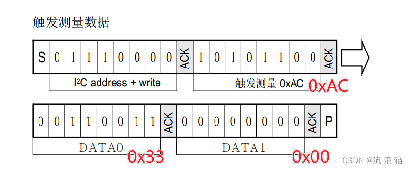
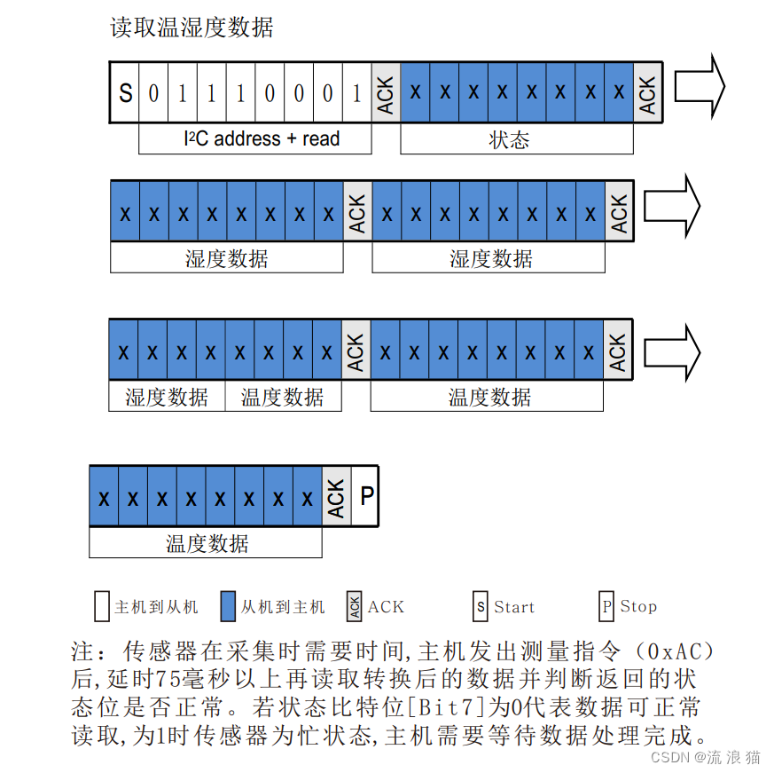
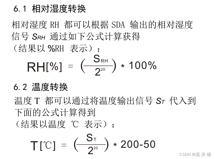
The temperature and humidity data of AHT20 (75ms after receiving the measurement signal) will continuously obtain 6 bytes of data. The first data obtained is the status of AHT20. We will not discuss the status in this article. The next 5 bytes of data are what we need to know, which are humidity data and temperature data.
The final temperature and humidity data conversion formula is as shown in the figure below, just understand it
2. Understand the DMA related interrupt flag bits and the corresponding DMA channel of I2C
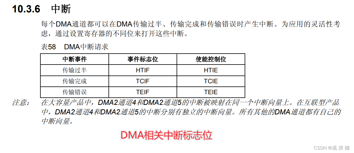
Because in this program, I need to perform certain processing on the data after the DMA receives it (store the temperature and humidity separately), I put this process in the interrupt generated after the DMA reception is completed. ; In addition, after the DMA transmission is completed, I perform the shutdown hardware IIC operation in its interrupt (AHT20 requires this step, without this step, the AHT20 will not start data measurement even if it waits for more events). After you complete the study, you can change the code of this article. The above operations can also be achieved without interrupts, even if it is an after-school exercise.
So let’s take a look at the DMA interrupt related content first. In this article, we only use the DMA transfer completion interrupt, which is the (TCIF event flag bit) in the figure below. The transfer completion and The transmission error flag is not used. You can learn about it and change the code later to make your code more robust.
STM32F103 has two IIC interfaces, Both I2C1 and I2C2 DMA requests are passed to DMA1, where the requests of I2C1 are respectively connected to channel 6 and channel 7 of DMA1. For the microcontroller, channel 6 of DMA1 is responsible for the data transmission of I2C1, and channel 7 of DMA1 is responsible for the data reception of I2C1.
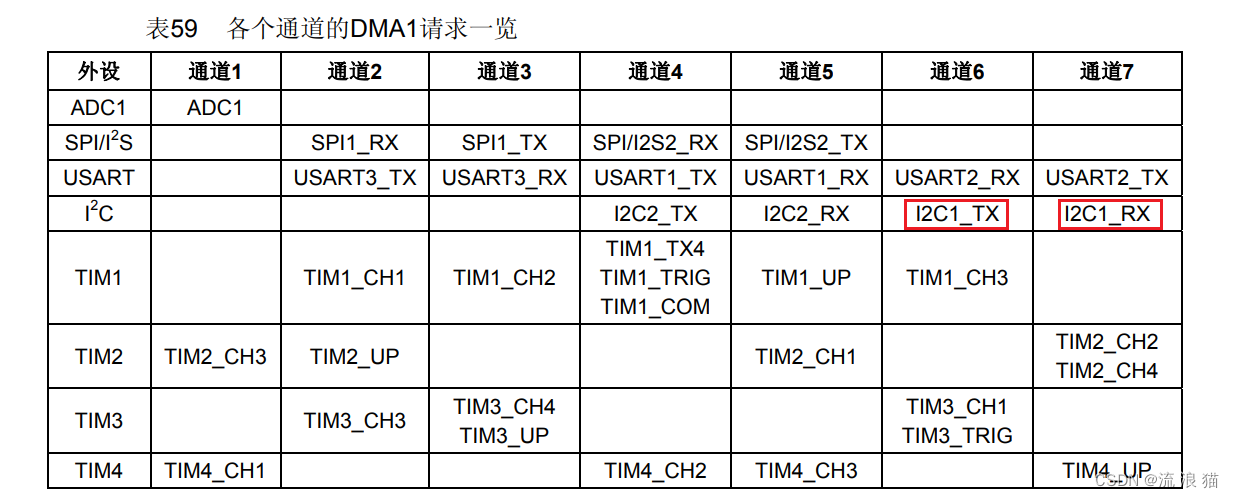
In the program of this article, we will use the PB6 and PB7 pins of the STM32F103 microcontroller, which correspond to the SCL and SDA of I2C1 respectively.
˜Relevant interrupt function names: DMA1_Channel6_IRQHandler, DMA1_Channel7_IRQHandler
void DMA1_Channel6_IRQHandler(void)  // DMA1通道6中断函数,即DMA完成I2C1相关数据发送搬运后发生的中断
void DMA1_Channel7_IRQHandler(void)  // DMA1通道7中断函数,即DMA完成I2C1相关数据接收搬运后发生的中断
3. This article mentions the relevant variable definitions in the program to understand in advance.
| variable name | effect | Remark |
|---|---|---|
| uint8_t Send_AC_Flag | Helper program to determine whether to send AC command | True means it can be sent |
| uint8_t DMA_BusyFlag | Check if DMA is busy | True means busy status |
| uint8_t AHT20_Data[6] | This array is an array that stores the data measured by AHT20. | Note that the array needs to be defined as uint8_t, otherwise an error will occur, because DMA transfers data in the form of bytes (it is up to you to define whether it is a byte, word or half-word, and it needs to be transmitted in the form of bytes here). |
| uint32_t wenshidu[2] | This array is the temperature and humidity data obtained by processing | This array needs to be defined as uint32_t, because the temperature and humidity data are all 20 bits in size. If the definition is too small, the data reception will be incomplete. |
| static uint8_t AC[3] | AHT20 measurement instruction array | none |
#define AHT20_ADDRESS (0x38 << 1)  // AHT20设备地址

uint8_t Send_AC_Flag = 1;  // 是否发送AC指令标志
uint8_t DMA_BusyFlag = 0;  // DMA是否繁忙标志

uint8_t AHT20_Data[6] = {

    0};  // 接收AHT20测量数据数组
uint32_t wenshidu[2] = {

    0x00};  // 对AHT20_Data[6]数组进行数据处理后得到的湿度、温度数据数组

static uint8_t AC[3] = {

    0xAC,0x33,0x00};  // AHT20开始测量指令
4. Understand in advance the DMA+IIC data sending and receiving process and the related functions in the program used in this article
4.1 DMA+IIC data sending and receiving process
For IIC+DMA, it is confusing to talk about sending and receiving at the same time, and it is difficult to understand. Everyone does not know much about this, so this article is based on this: Let’s first look at the simpler use of IIC +DMA completes the process of data sending (that is, sending instructions in the AC array). After understanding this, we will look at the slightly more difficult data receiving process, and then merge the two processes together to complete the process of DMA participating in I2C1 data sending. Data handling work, and also participates in the handling work when receiving data.
For data transfer or reception, the early initialization steps are necessary and roughly the same, because this is required in all three studies, so I will explain it in this section. That is, the related functions mentioned in [4.2. Understand the relevant functions in the program used in this article in advance] below.
In this program, we will use this process to complete the understanding of the code. (You don’t need to read all three at once, you can read one The experiment is followed by completing an experiment) :
① Use IIC+DMA to complete the process of data transmission During this process, we It's probably like this. First initialize the relevant GPIO port configuration, I2C configuration, DMA configuration, and NVIC related configuration, and then turn on the I2C1 counter for DMA (I2C_DMACmd(I2C1,ENABLE);). After that, we need to use the hardware IIC for the preliminary stage. Address + read and write bits write are sent, and then DMA can be used to transfer the data to the DR register, and the data will be processed by the shift register of the I2C1 hardware After sending, waiting for the data to be sent, the DMA will apply for an interrupt to the CPU. In the interrupt, we will stop the I2C1 communication. After that, we will use ordinary IIC to read the data.
② Use IIC+DMA to complete the process of data reception In this process, we are probably like this, we still initialize the relevant GPIO port configuration and I2C configuration first , DMA configuration, NVIC related configuration, and then open the counter of I2C1 to DMA (I2C_DMACmd(I2C1,ENABLE);), then we need to use the hardware IIC to perform the early address + read and write bit read is sent, and then DMA can be used to transfer data from the DR register and written to the AHT20_Data[6] array. Waiting for the data reception to be completed, the DMA will still apply for an interrupt to the CPU. We are The data is processed accordingly in this interrupt, and the processed data is put into the wenshidu[2] array.
③ Use IIC+DMA to complete the process of data sending + receiving In this process, it is probably like this, still initialize the relevant GPIO port configuration and I2C configuration first , DMA configuration, NVIC related configuration, and then open the counter of I2C1 to DMA (I2C_DMACmd(I2C1,ENABLE);). After that, we need to use the hardware IIC to perform the early address + read and write bit write is sent by using DMA to transfer the data to the DR register, and the shift register of the I2C1 hardware is used to send the data. Waiting for the data to be sent, the DMA will apply for an interrupt to the CPU. We are here Stop the I2C1 communication during the interrupt, and then wait for the response time (the data sheet is 75ms, we stop for 80ms). The following is similar to experiment ②, using hardware IIC to perform the early address + read and write bits read and then using DMA to transfer data from the DR register. And written to the AHT20_Data[6] array. When the data reception is completed, the DMA will still apply for an interrupt to the CPU. We process the data accordingly in the interrupt, and the processed data is placed in the wenshidu[2] array. .
4.2. Understand the relevant functions in the program used in this article in advance
AHT20_I2C_InitConfig(void) Initialize the GPIO pins, I2C1 and other related configurations of STM32F103
For code:
I2C1->CR1 |= 0x8000; // 手动清除清BUSY
I2C1->CR1 &= ~0x8000;
Because many times, due to the reasons of the STM32 hardware itself, the I2C bus may be always busy. This is an erroneous indication. If the BUSY bit of I2C is not cleared when initializing the IIC, there is a high chance that our program will Will be stuck.
For related explanations and processing methods, see STM32 I2C_FLAG_BUSY setting solution and stm32f1 hardware I2C busy problem, if you are interested, you can learn about it. I will simply handle it manually during initialization.
void AHT20_I2C_InitConfig(void)
{


	delay_init();
	/******* 启用GPIO配置和时钟  *********/
	RCC_APB1PeriphClockCmd(RCC_APB1Periph_I2C1,ENABLE);
	RCC_APB2PeriphClockCmd(RCC_APB2Periph_GPIOB,ENABLE);


	/*********** GPIO口相关配置 **********/
	GPIO_InitTypeDef GPIO_InitStructer;
	GPIO_InitStructer.GPIO_Mode = GPIO_Mode_AF_OD;  // 注意这里要将GPIO口设置为复用开漏模式
	GPIO_InitStructer.GPIO_Pin = GPIO_Pin_6 | GPIO_Pin_7;
	GPIO_InitStructer.GPIO_Speed = GPIO_Speed_50MHz;
	GPIO_Init(GPIOB,&GPIO_InitStructer);

	/*********** I2C外设配置 **********/
	I2C_DeInit(I2C1);

	I2C1->CR1 |= 0x8000;  // 手动清除清BUSY
	I2C1->CR1 &= ~0x8000;

	I2C_InitTypeDef I2C1_InitStructer;
	I2C1_InitStructer.I2C_Ack = I2C_Ack_Enable;
	I2C1_InitStructer.I2C_AcknowledgedAddress = I2C_AcknowledgedAddress_7bit;
	I2C1_InitStructer.I2C_ClockSpeed = I2C_SPEED; // 太高容易卡死
	I2C1_InitStructer.I2C_DutyCycle = I2C_DutyCycle_2;
	I2C1_InitStructer.I2C_Mode = I2C_Mode_I2C;
	I2C1_InitStructer.I2C_OwnAddress1 = MCU_I2C1_ADDRESS;

	I2C_Cmd(I2C1,ENABLE);
	I2C_Init(I2C1,&I2C1_InitStructer);

	RCC_AHBPeriphClockCmd(RCC_AHBPeriph_DMA1, ENABLE);  //使能DMA传输,因为DMA在I2C发送数据和接收数据的时候都需要使能DMA1,如果这里不使能的话后期需要多次使能,所以我就在这里使能了,各位根据自己实际情况进行使能。
}
MY_DMA_Transmit_InitConfig(void) I2C1 needs to initialize the DMA function when sending data. Channel 6 of DMA1 will be initialized here.
Pay attention to the transmission of data here. Direction: DMA_InitStructer.DMA_DIR = DMA_DIR_PeripheralDST; // Send data to the peripheral, and the DR register of I2C1 serves as the data receiver
Key points: Why do I want to transfer 3 pieces of data, that is, the data in array AC, but below DMA_InitStructer.DMA_BufferSize = 4; Why is it set to 4 data?
I will not explain in detail here, but will attach a link to an article for you to find the answer yourself: [STM32] IIC sends data during DMA transmission There is always one missing problem
Because DMA is used to complete the transfer of data from the AC array to the DR register of I2C1 and the interrupt generated to stop the I2C1 hardware communication function (explained above, in [2. Understand DMA related interrupt flag bits and I2C corresponding DMA channels] are in this section), so the relevant modules of NVIC are also configured here. You can configure them according to your actual situation.
void MY_DMA_Transmit_InitConfig(void)
{


	RCC_AHBPeriphClockCmd(RCC_AHBPeriph_DMA1, ENABLE);  //使能DMA传输
	DMA_DeInit(DMA1_Channel6);

	DMA_InitTypeDef DMA_InitStructer;
	DMA_InitStructer.DMA_PeripheralBaseAddr = (uint32_t)&I2C1->DR;   // 注意这里取地址不要忘记加上 & 符号
	DMA_InitStructer.DMA_PeripheralDataSize = DMA_PeripheralDataSize_Byte;
	DMA_InitStructer.DMA_PeripheralInc = DMA_PeripheralInc_Disable;  // DR寄存器位置固定,就那一个,所以不能使得指针传输完移动

	DMA_InitStructer.DMA_MemoryBaseAddr = (uint32_t)AC;
	DMA_InitStructer.DMA_MemoryDataSize = DMA_PeripheralDataSize_Byte;
	DMA_InitStructer.DMA_MemoryInc = DMA_MemoryInc_Enable;  // AC数组这边的指针需要不断自增,这样才能将数据轮流发送出去,而不是只发数组中的第一个

	DMA_InitStructer.DMA_Mode = DMA_Mode_Normal;   // DMA设定为正常模式
	DMA_InitStructer.DMA_DIR = DMA_DIR_PeripheralDST;  // 发送数据到外设
	DMA_InitStructer.DMA_M2M = DMA_M2M_Disable;  // 注意不适用软件触发

	DMA_InitStructer.DMA_BufferSize = 4;
	DMA_InitStructer.DMA_Priority = DMA_Priority_VeryHigh;
	DMA_Init(DMA1_Channel6,&DMA_InitStructer);

	NVIC_InitTypeDef NVIC_InitStructure;
	//中断优先级NVIC设置
	NVIC_InitStructure.NVIC_IRQChannel = DMA1_Channel6_IRQn;  //DMA中断
	NVIC_InitStructure.NVIC_IRQChannelPreemptionPriority = 0;  //先占优先级0级
	NVIC_InitStructure.NVIC_IRQChannelSubPriority = 1;  //从优先级1级
	NVIC_InitStructure.NVIC_IRQChannelCmd = ENABLE; //IRQ通道被使能
	NVIC_Init(&NVIC_InitStructure);  //初始化NVIC寄存器

	/* 启用DMA Channel6完全传输中断 */
	DMA_ITConfig(DMA1_Channel6, DMA_IT_TC, ENABLE);
}
MY_DMA_Receive_InitConfig(void) I2C1 needs to initialize the DMA function when receiving data. Channel 7 of DMA1 will be initialized here.
Pay attention to the transmission of data here. Direction: DMA_InitStructer.DMA_DIR = DMA_DIR_PeripheralSRC; // Receive data from peripherals, and the DR register of I2C1 serves as the data sender (the data in the DR register of I2C1 is Sent by AHT20)
DMA_InitStructer.DMA_BufferSize = 6; It is normal when receiving here. It does not need to be like when sending, the DMA value is more than the sent data. One, AHT20 will return 6 bytes of data. Different peripherals return different data lengths. You can configure it according to your own peripherals.
I don’t know if you have noticed the priority configuration problem. In order to avoid the stuck, I chose to make the priority of DMA+I2C1 data transmission greater than the priority of DMA+I2C1 data reception. Here everyone You can design it according to your own needs, but according to the official, it is recommended that when using DMA+I2C1, the priority should be set higher.
Similarly, here is also the relevant configuration of the NVIC to be used
void MY_DMA_Receive_InitConfig(void)
{


	DMA_DeInit(DMA1_Channel7);

	DMA_InitTypeDef DMA_Receive_InitStructer;
	DMA_Receive_InitStructer.DMA_PeripheralBaseAddr = (uint32_t)&I2C1->DR;   // 注意这里取地址不要忘记加上 & 符号
	DMA_Receive_InitStructer.DMA_PeripheralDataSize = DMA_PeripheralDataSize_Byte;
	DMA_Receive_InitStructer.DMA_PeripheralInc = DMA_PeripheralInc_Disable;  // DR寄存器位置固定,就那一个,所以不能使得指针传输完移动

	DMA_Receive_InitStructer.DMA_MemoryBaseAddr = (uint32_t)AHT20_Data;
	DMA_Receive_InitStructer.DMA_MemoryDataSize = DMA_PeripheralDataSize_Byte;
	DMA_Receive_InitStructer.DMA_MemoryInc = DMA_MemoryInc_Enable;  // AHT20_Data 这边需要指针不断加1,这样才能不覆盖接收到的数据

	DMA_Receive_InitStructer.DMA_Mode = DMA_Mode_Normal;   // DMA设定为正常模式
	DMA_Receive_InitStructer.DMA_DIR = DMA_DIR_PeripheralSRC;   // 从外设接收数据,I2C1的DR寄存器作为数据发送方(I2C1的DR寄存器内数据由AHT20发送来的)
	DMA_Receive_InitStructer.DMA_M2M = DMA_M2M_Disable;  // 注意不适用软件触发

	DMA_Receive_InitStructer.DMA_BufferSize = 6;
	DMA_Receive_InitStructer.DMA_Priority = DMA_Priority_High;
	DMA_Init(DMA1_Channel7,&DMA_Receive_InitStructer);

	NVIC_InitTypeDef NVIC_InitStructure;
	//中断优先级NVIC设置
	NVIC_InitStructure.NVIC_IRQChannel = DMA1_Channel7_IRQn;  //DMA中断
	NVIC_InitStructure.NVIC_IRQChannelPreemptionPriority = 0;  //先占优先级0级
	NVIC_InitStructure.NVIC_IRQChannelSubPriority = 2;  //从优先级1级
	NVIC_InitStructure.NVIC_IRQChannelCmd = ENABLE; //IRQ通道被使能
	NVIC_Init(&NVIC_InitStructure);  //初始化NVIC寄存器

	/* 启用DMA Channel7完全传输中断 */
	DMA_ITConfig(DMA1_Channel7, DMA_IT_TC, ENABLE);
}
AHT20_DMA_Transfer(void) This function is used in the step of IIC sending data; it can be used after the hardware IIC completes the start command and sends the AHT20 address + write command. DMA moves the data in the AC array to the DR register of I2C1
AHT20_DMA_Recevie(void) This function is used in the step of IIC receiving data; it is completed in the hardware IIC Use the start command and after sending the AHT20 address + read command to complete the DMA transfer of the data in the DR register of I2C1 to the AHT20_Data[6] array
//开启一次DMA传输
void AHT20_DMA_Transfer(void)
{


	DMA_Cmd(DMA1_Channel6, DISABLE ); 						  //关闭 DMA 所指示的通道
 	DMA_SetCurrDataCounter(DMA1_Channel6, 4);	//DMA通道的DMA缓存的大小
 	DMA_Cmd(DMA1_Channel6, ENABLE);  								//使能 DMA 所指示的通道
}

//开启一次DMA传输接收数据
void AHT20_DMA_Recevie(void)
{


	DMA_Cmd(DMA1_Channel7, DISABLE ); 						  //关闭 DMA 所指示的通道
 	DMA_SetCurrDataCounter(DMA1_Channel7, 6);	      //DMA通道的DMA缓存的大小
 	DMA_Cmd(DMA1_Channel7, ENABLE);  								//使能 DMA 所指示的通道
}
5. Experiment 1 Use IIC+DMA to complete the process of data transmission
5.1 The relevant functions in this experiment are as follows
AHT20_SendAC(void) This function is used by IIC+DMA when I2C completes data transmission.
In this function, first determine whether the system allows sending AC instructions. Because during initialization, we assigned the value of Send_AC_Flag to 1, so the function will be entered here, and the flag will be completed in DMA After the data is transferred from AC to the DR register, it is set to 0, and after the data reception is completed using ordinary hardware IIC, it is set to 1 (that is, the AC command is allowed to be sent next time); after judging that the AC command can be sent, it is necessary to determine whether the DMA is in a busy state. DMA can be used to complete data transfer only when DMA is idle. When DMA starts to transfer data, the flag bit is set to 1. Subsequently, in the interrupt after DMA completes data transfer, we clear the flag bit. In this program, the flag bit is Clear also indicates that the data was sent successfully. (It is recommended to read the following content after reading the AHT20_SendAC(void) function)
After entering the program, it will first determine whether the I2C1 bus is busy. If so, wait for I2C1 to complete it. The work at hand, but to save trouble, I directly added an infinite loopwhile(I2C_GetFlagStatus(I2C1, I2C_FLAG_BUSY)); It’s easy to get stuck here , everyone will deal with it accordingly later, and we won’t care about it here.
The next step is to use hardware IIC. The common beginning is to turn on I2C1 first, then send the device address + read and write instructions, and wait for the response from the device to be used. AHT20_DMA_Transfer(); The function completes the sending of the start measurement command, and the rest is executed in the interrupt.
Extra: Since DMA can complete the transfer of data, and the DR register can also automatically move data to the shift register, why do you still have to use it?I2C_Send7bitAddress(I2C1, AHT20_ADDRESS, I2C_Direction_Transmitter); This function completes the sending of data. Why not write the AC array as uint8_t AC[4] = {0x70,0xAC,0x33,0x00} like this, then Replace the statement I2C_Send7bitAddress(I2C1, AHT20_ADDRESS, I2C_Direction_Transmitter);?
In fact, I thought so at first and tried it. Unfortunately, it failed. Later I looked through the reference manual and it said this:
So I think the transmission data flag bit applied by IIC to DMA is only EV8, and EV6 is not processed (when IIC is sending data)
void AHT20_SendAC(void)
{


	if(Send_AC_Flag)
	{


		if(DMA_BusyFlag == 0)
		{


			while(I2C_GetFlagStatus(I2C1, I2C_FLAG_BUSY));

			I2C_GenerateSTART(I2C1, ENABLE);//开启I2C1
			while(!I2C_CheckEvent(I2C1, I2C_EVENT_MASTER_MODE_SELECT));/*EV5,主模式*/

			I2C_Send7bitAddress(I2C1, AHT20_ADDRESS, I2C_Direction_Transmitter);//器件地址
			while(!I2C_CheckEvent(I2C1, I2C_EVENT_MASTER_TRANSMITTER_MODE_SELECTED));

			AHT20_DMA_Transfer();

			Send_AC_Flag = 0;    // 是否发送AC指令标志位,发送完成AC指令,清除标志位,等待接收数据程序完成数据接收后可以重新拉高该标志位
			DMA_BusyFlag = 1;   // DMA繁忙标志位置位,等待DMA完成进入中断后清除繁忙标志位
		}
		else
		{


			return;
		}
	}
	else
	{


		return;
	}
}
AHT20_Measure1(void) This function is a function for ordinary hardware IIC to receive data. Here we put the received data in the AHT20_Data[6] array, and The processed data is placed in the wenshidu[2] array. I won’t go into details here. You can understand it yourself.
void AHT20_Measure1(void)
{


	uint32_t TempData = 0;   // 这里需要提前设置两个参数接收温湿度数据,不可以直接放在wenshidu[2]数组中
	uint32_t HumiData = 0;

	if(Send_AC_Flag == 0)
	{


		delay_ms(80);  // 这里延时的80ms后期要进行修改,太占用cpu资源

		I2C_GenerateSTART(I2C1,ENABLE);
		while(I2C_CheckEvent(I2C1,I2C_EVENT_MASTER_MODE_SELECT) != SUCCESS);  // EV5事件  // EV5事件

		I2C_Send7bitAddress(I2C1,AHT20_ADDRESS,I2C_Direction_Receiver);
		while(I2C_CheckEvent(I2C1,I2C_EVENT_MASTER_RECEIVER_MODE_SELECTED) != SUCCESS);  // EV6事件


		while(I2C_CheckEvent(I2C1,I2C_EVENT_MASTER_BYTE_RECEIVED) != SUCCESS);  // EV7事件
		AHT20_Data[0] = I2C_ReceiveData(I2C1);

		while(I2C_CheckEvent(I2C1,I2C_EVENT_MASTER_BYTE_RECEIVED) != SUCCESS);  // EV7事件
		AHT20_Data[1] = I2C_ReceiveData(I2C1);

		while(I2C_CheckEvent(I2C1,I2C_EVENT_MASTER_BYTE_RECEIVED) != SUCCESS);  // EV7事件
		AHT20_Data[2] = I2C_ReceiveData(I2C1);

		while(I2C_CheckEvent(I2C1,I2C_EVENT_MASTER_BYTE_RECEIVED) != SUCCESS);  // EV7事件
		AHT20_Data[3] = I2C_ReceiveData(I2C1);

		while(I2C_CheckEvent(I2C1,I2C_EVENT_MASTER_BYTE_RECEIVED) != SUCCESS);  // EV7事件
		AHT20_Data[4] = I2C_ReceiveData(I2C1);

		I2C_AcknowledgeConfig(I2C1,DISABLE);  // 主机发送不再接收信号
		I2C_GenerateSTOP(I2C1,ENABLE);        // 截至信号

		while(I2C_CheckEvent(I2C1,I2C_EVENT_MASTER_BYTE_RECEIVED) != SUCCESS);  // EV7事件
		AHT20_Data[5] = I2C_ReceiveData(I2C1);

		I2C_AcknowledgeConfig(I2C1,ENABLE);

		HumiData = HumiData | AHT20_Data[1];
		HumiData = (HumiData << 8) | AHT20_Data[2];
		HumiData = (HumiData << 4) | (AHT20_Data[3] >> 4);

		TempData = TempData | (0x0F & AHT20_Data[3]);
		TempData = (TempData << 8) | AHT20_Data[4];
		TempData = (TempData << 8) | AHT20_Data[5];

		wenshidu[0] = HumiData;
		wenshidu[1] = TempData;
		Send_AC_Flag = 1;
	}
	else
		return;
}
AHT20_DMA_I2C_Init2(void) This function is a function that combines several previous functions. Calling this function once in the main program can obtain measurement data.
void AHT20_DMA_I2C_Init1(void)
{


	delay_init();
	AHT20_I2C_InitConfig();

	MY_DMA_Transmit_InitConfig();
	I2C_DMACmd(I2C1,ENABLE);

	AHT20_SendAC();
	AHT20_Measure1();
}
DMA1_Channel6_IRQHandler(void) This function is an interrupt generated after DMA completes the data transfer during the process of IIC sending data. We need to close the IIC bus and clear DMA busy in this function. Flag bit
void DMA1_Channel6_IRQHandler(void)
{


	if(DMA_GetFlagStatus(DMA1_FLAG_TC6))
	{


		DMA_ClearFlag(DMA1_FLAG_TC6);

		delay_us(10); // 这里如果有一个ms级别的延时,直接将程序卡死,无法测量数据
		I2C_GenerateSTOP(I2C1, ENABLE);      //关闭I2C1总线
		I2C_AcknowledgeConfig(I2C1,ENABLE);

		DMA_BusyFlag = 0;    //清除复位忙碌标志
	}
}
5.2 Experiment 1 Integration General Procedure
/*
 * AHT20_DMA.h 程序
 */
#ifndef __AHT20_DMA_H
#define __AHT20_DMA_H
#include "stm32f10x.h"                  // Device header
#define MCU_I2C1_ADDRESS  0x60          //单片机作为从机时的地址,该处地址的前五位不能是11110
#define I2C_SPEED         50000

extern uint8_t Send_AC_Flag;	//是否发送AC指令标志位
extern uint8_t DMA_BusyFlag;	//DMA忙碌标志位

extern uint8_t AHT20_Data[6];
extern uint32_t wenshidu[2];

void AHT20_DMA_I2C_Init1(void);

#endif
/*
 *  AHT20_DMA.C 程序
 */
#include "AHT20_DMA.h"
#include "delay.h"

#define AHT20_ADDRESS (0x38 << 1)  // AHT20设备地址

uint8_t Send_AC_Flag = 1;  // 是否发送AC指令标志
uint8_t DMA_BusyFlag = 0;  // DMA是否繁忙标志

uint8_t AHT20_Data[6] = {

    0};  // 接收AHT20测量数据数组
uint32_t wenshidu[2] = {

    0x00};  // 对AHT20_Data[6]数组进行数据处理后得到的湿度、温度数据数组

static uint8_t AC[3] = {

    0xAC,0x33,0x00};  // AHT20开始测量指令


void AHT20_I2C_InitConfig(void)
{


	delay_init();
	/******* 启用GPIO配置和时钟  *********/
	RCC_APB1PeriphClockCmd(RCC_APB1Periph_I2C1,ENABLE);
	RCC_APB2PeriphClockCmd(RCC_APB2Periph_GPIOB,ENABLE);


	/*********** GPIO口相关配置 **********/
	GPIO_InitTypeDef GPIO_InitStructer;
	GPIO_InitStructer.GPIO_Mode = GPIO_Mode_AF_OD;  // 注意这里要将GPIO口设置为复用开漏模式
	GPIO_InitStructer.GPIO_Pin = GPIO_Pin_6 | GPIO_Pin_7;
	GPIO_InitStructer.GPIO_Speed = GPIO_Speed_50MHz;
	GPIO_Init(GPIOB,&GPIO_InitStructer);

	/*********** I2C外设配置 **********/
	I2C_DeInit(I2C1);

	I2C1->CR1 |= 0x8000;  // 手动清除清BUSY
	I2C1->CR1 &= ~0x8000;

	I2C_InitTypeDef I2C1_InitStructer;
	I2C1_InitStructer.I2C_Ack = I2C_Ack_Enable;
	I2C1_InitStructer.I2C_AcknowledgedAddress = I2C_AcknowledgedAddress_7bit;
	I2C1_InitStructer.I2C_ClockSpeed = I2C_SPEED; // 太高容易卡死
	I2C1_InitStructer.I2C_DutyCycle = I2C_DutyCycle_2;
	I2C1_InitStructer.I2C_Mode = I2C_Mode_I2C;
	I2C1_InitStructer.I2C_OwnAddress1 = MCU_I2C1_ADDRESS;

	I2C_Cmd(I2C1,ENABLE);
	I2C_Init(I2C1,&I2C1_InitStructer);

	RCC_AHBPeriphClockCmd(RCC_AHBPeriph_DMA1, ENABLE);  //使能DMA传输,因为DMA在I2C发送数据和接收数据的时候都需要使能DMA1,如果这里不使能的话后期需要多次使能,所以我就在这里使能了,各位根据自己实际情况进行使能。
}


void MY_DMA_Transmit_InitConfig(void)
{


	RCC_AHBPeriphClockCmd(RCC_AHBPeriph_DMA1, ENABLE);  //使能DMA传输
	DMA_DeInit(DMA1_Channel6);

	DMA_InitTypeDef DMA_InitStructer;
	DMA_InitStructer.DMA_PeripheralBaseAddr = (uint32_t)&I2C1->DR;   // 注意这里取地址不要忘记加上 & 符号
	DMA_InitStructer.DMA_PeripheralDataSize = DMA_PeripheralDataSize_Byte;
	DMA_InitStructer.DMA_PeripheralInc = DMA_PeripheralInc_Disable;  // DR寄存器位置固定,就那一个,所以不能使得指针传输完移动

	DMA_InitStructer.DMA_MemoryBaseAddr = (uint32_t)AC;
	DMA_InitStructer.DMA_MemoryDataSize = DMA_PeripheralDataSize_Byte;
	DMA_InitStructer.DMA_MemoryInc = DMA_MemoryInc_Enable;  // AC数组这边的指针需要不断自增,这样才能将数据轮流发送出去,而不是只发数组中的第一个

	DMA_InitStructer.DMA_Mode = DMA_Mode_Normal;   // DMA设定为正常模式
	DMA_InitStructer.DMA_DIR = DMA_DIR_PeripheralDST;  // 发送数据到外设
	DMA_InitStructer.DMA_M2M = DMA_M2M_Disable;  // 注意不适用软件触发

	DMA_InitStructer.DMA_BufferSize = 4;
	DMA_InitStructer.DMA_Priority = DMA_Priority_VeryHigh;
	DMA_Init(DMA1_Channel6,&DMA_InitStructer);

	NVIC_InitTypeDef NVIC_InitStructure;
	//中断优先级NVIC设置
	NVIC_InitStructure.NVIC_IRQChannel = DMA1_Channel6_IRQn;  //DMA中断
	NVIC_InitStructure.NVIC_IRQChannelPreemptionPriority = 0;  //先占优先级0级
	NVIC_InitStructure.NVIC_IRQChannelSubPriority = 1;  //从优先级1级
	NVIC_InitStructure.NVIC_IRQChannelCmd = ENABLE; //IRQ通道被使能
	NVIC_Init(&NVIC_InitStructure);  //初始化NVIC寄存器

	/* 启用DMA Channel6完全传输中断 */
	DMA_ITConfig(DMA1_Channel6, DMA_IT_TC, ENABLE);
}


//开启一次DMA传输
void AHT20_DMA_Transfer(void)
{


	DMA_Cmd(DMA1_Channel6, DISABLE ); 						  //关闭 DMA 所指示的通道
 	DMA_SetCurrDataCounter(DMA1_Channel6, 4);	//DMA通道的DMA缓存的大小
 	DMA_Cmd(DMA1_Channel6, ENABLE);  								//使能 DMA 所指示的通道
}


void AHT20_SendAC(void)
{


	if(Send_AC_Flag)
	{


		if(DMA_BusyFlag == 0)
		{


			while(I2C_GetFlagStatus(I2C1, I2C_FLAG_BUSY));

			I2C_GenerateSTART(I2C1, ENABLE);//开启I2C1
			while(!I2C_CheckEvent(I2C1, I2C_EVENT_MASTER_MODE_SELECT));/*EV5,主模式*/

			I2C_Send7bitAddress(I2C1, AHT20_ADDRESS, I2C_Direction_Transmitter);//器件地址
			while(!I2C_CheckEvent(I2C1, I2C_EVENT_MASTER_TRANSMITTER_MODE_SELECTED));

			AHT20_DMA_Transfer();

			Send_AC_Flag = 0;    // 是否发送AC指令标志位,发送完成AC指令,清除标志位,等待接收数据程序完成数据接收后可以重新拉高该标志位
			DMA_BusyFlag = 1;   // DMA繁忙标志位置位,等待DMA完成进入中断后清除繁忙标志位
		}
		else
		{


			return;
		}
	}
	else
	{


		return;
	}
}


void AHT20_Measure1(void)
{


	uint32_t TempData = 0;   // 这里需要提前设置两个参数接收温湿度数据,不可以直接放在wenshidu[2]数组中
	uint32_t HumiData = 0;

	if(Send_AC_Flag == 0)
	{


		delay_ms(80);  // 这里延时的80ms后期要进行修改,太占用cpu资源

		I2C_GenerateSTART(I2C1,ENABLE);
		while(I2C_CheckEvent(I2C1,I2C_EVENT_MASTER_MODE_SELECT) != SUCCESS);  // EV5事件  // EV5事件

		I2C_Send7bitAddress(I2C1,AHT20_ADDRESS,I2C_Direction_Receiver);
		while(I2C_CheckEvent(I2C1,I2C_EVENT_MASTER_RECEIVER_MODE_SELECTED) != SUCCESS);  // EV6事件


		while(I2C_CheckEvent(I2C1,I2C_EVENT_MASTER_BYTE_RECEIVED) != SUCCESS);  // EV7事件
		AHT20_Data[0] = I2C_ReceiveData(I2C1);

		while(I2C_CheckEvent(I2C1,I2C_EVENT_MASTER_BYTE_RECEIVED) != SUCCESS);  // EV7事件
		AHT20_Data[1] = I2C_ReceiveData(I2C1);

		while(I2C_CheckEvent(I2C1,I2C_EVENT_MASTER_BYTE_RECEIVED) != SUCCESS);  // EV7事件
		AHT20_Data[2] = I2C_ReceiveData(I2C1);

		while(I2C_CheckEvent(I2C1,I2C_EVENT_MASTER_BYTE_RECEIVED) != SUCCESS);  // EV7事件
		AHT20_Data[3] = I2C_ReceiveData(I2C1);

		while(I2C_CheckEvent(I2C1,I2C_EVENT_MASTER_BYTE_RECEIVED) != SUCCESS);  // EV7事件
		AHT20_Data[4] = I2C_ReceiveData(I2C1);

		I2C_AcknowledgeConfig(I2C1,DISABLE);  // 主机发送不再接收信号
		I2C_GenerateSTOP(I2C1,ENABLE);        // 截至信号

		while(I2C_CheckEvent(I2C1,I2C_EVENT_MASTER_BYTE_RECEIVED) != SUCCESS);  // EV7事件
		AHT20_Data[5] = I2C_ReceiveData(I2C1);

		I2C_AcknowledgeConfig(I2C1,ENABLE);

		HumiData = HumiData | AHT20_Data[1];
		HumiData = (HumiData << 8) | AHT20_Data[2];
		HumiData = (HumiData << 4) | (AHT20_Data[3] >> 4);

		TempData = TempData | (0x0F & AHT20_Data[3]);
		TempData = (TempData << 8) | AHT20_Data[4];
		TempData = (TempData << 8) | AHT20_Data[5];

		wenshidu[0] = HumiData;
		wenshidu[1] = TempData;
		Send_AC_Flag = 1;
	}
	else
		return;
}


void AHT20_DMA_I2C_Init1(void)
{


	delay_init();
	AHT20_I2C_InitConfig();

	MY_DMA_Transmit_InitConfig();
	I2C_DMACmd(I2C1,ENABLE);

	AHT20_SendAC();
	AHT20_Measure1();
}


void DMA1_Channel6_IRQHandler(void)
{


	if(DMA_GetFlagStatus(DMA1_FLAG_TC6))
	{


		DMA_ClearFlag(DMA1_FLAG_TC6);

		delay_us(10); // 这里如果有一个ms级别的延时,直接将程序卡死,无法测量数据
		I2C_GenerateSTOP(I2C1, ENABLE);      //关闭I2C1总线
		I2C_AcknowledgeConfig(I2C1,ENABLE);

		DMA_BusyFlag = 0;    //清除复位忙碌标志
	}
}
6. Experiment 2: Use IIC+DMA to complete the data reception process
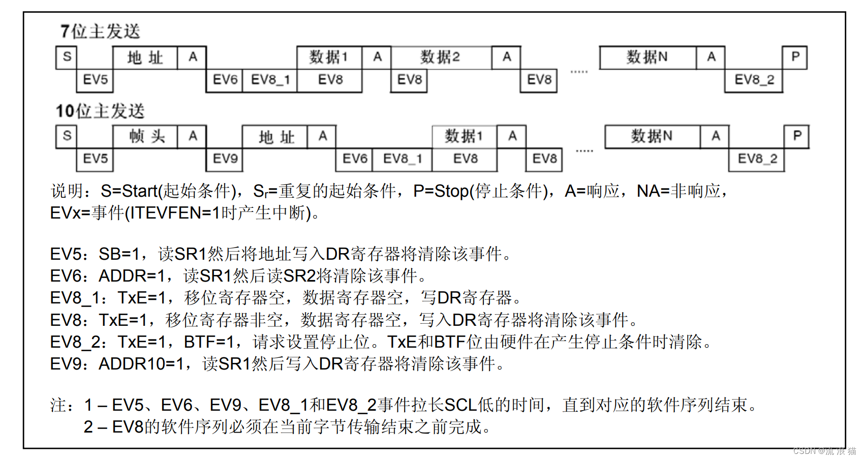
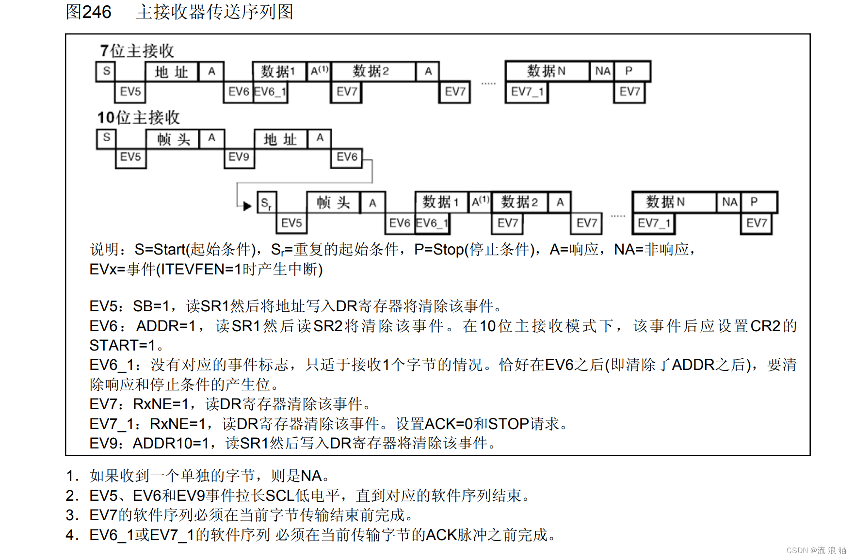
The data reception of IIC is different from the data transmission of IIC. When IIC communication is used as the main receiver, the microcontroller needs to send different response bits according to different needs, such as the ordinary hardware IIC received in the first experiment. At that time, before receiving the last data, the microcontroller set I2C_AcknowledgeConfig(I2C1,DISABLE); to inform the IIC hardware in advance that the next data is I For the last data you want to receive, don't let the peripheral send it again after it has finished sending it. This is the operation of pulling the SDA bit high in the software. I2C_AcknowledgeConfig(I2C1,DISABLE);This step is also done for us, but the premise is that you You have to remind DMA to remember to talk to the hardware IIC. So how to remind DMA to remember to tell the peripheral not to send data? A new function is needed here:I2C_DMALastTransferCmd(I2C1,ENABLE);Before turning on DMA to transfer data, calling this function is equivalent to informing the DMA in advance. Remember to notify the hardware IIC to send a NACK, which is the acknowledgment bit that no longer receives data. Attached is a sequence diagram of the main receiver of the microcontroller IIC
6.1 The relevant functions of this experiment are as follows
I2C1_SendAC(void) This function uses hardware IIC to complete sending AC instructions, and no DMA is involved
void I2C1_SendAC(void)
{


	if(Send_AC_Flag)
	{


		if(DMA_BusyFlag == 0)
		{


			while(I2C_GetFlagStatus(I2C1, I2C_FLAG_BUSY));

			I2C_GenerateSTART(I2C1, ENABLE);  //开启I2C1
			while(!I2C_CheckEvent(I2C1, I2C_EVENT_MASTER_MODE_SELECT)); /*EV5,主模式*/

			I2C_Send7bitAddress(I2C1, AHT20_ADDRESS, I2C_Direction_Transmitter);//器件地址
			while(!I2C_CheckEvent(I2C1, I2C_EVENT_MASTER_TRANSMITTER_MODE_SELECTED));  // EV6事件

			I2C_SendData(I2C1,0xAC);
			while(I2C_CheckEvent(I2C1,I2C_EVENT_MASTER_BYTE_TRANSMITTING) != SUCCESS);; // EV8事件
			I2C_SendData(I2C1,0x33);
			while(I2C_CheckEvent(I2C1,I2C_EVENT_MASTER_BYTE_TRANSMITTING) != SUCCESS);  // EV8事件
			I2C_SendData(I2C1,0x00);
			while(I2C_CheckEvent(I2C1,I2C_EVENT_MASTER_BYTE_TRANSMITTED) != SUCCESS);  // EV8_2事件
			I2C_GenerateSTOP(I2C1,ENABLE);  //关闭I2C1

			Send_AC_Flag = 0;    // 是否发送AC指令标志位,发送完成AC指令,清除标志位,等待接收数据程序完成数据接收后可以重新拉高该标志位
		}
		else
		{


			return;
		}
	}
	else
	{


		return;
	}
}
I2C1_SendAC(void) This function is similar to the one in Experiment 1, but with one more lineI2C_DMALastTransferCmd(I2C1,ENABLE); I2C1_SendAC(void) a> That is, as mentioned above, the DMA is informed in advance that it is about to receive the data and then the hardware IIC is informed to send the NACK response bit.
void AHT20_Measure2(void)
{


	if(!Send_AC_Flag)
	{


		if(DMA_BusyFlag == 0)
		{


			while(I2C_GetFlagStatus(I2C1, I2C_FLAG_BUSY));

			I2C_GenerateSTART(I2C1,ENABLE);
			while(I2C_CheckEvent(I2C1,I2C_EVENT_MASTER_MODE_SELECT) != SUCCESS);  // EV5事件

			I2C_Send7bitAddress(I2C1,AHT20_ADDRESS,I2C_Direction_Receiver);
			while(I2C_CheckEvent(I2C1,I2C_EVENT_MASTER_RECEIVER_MODE_SELECTED) != SUCCESS);  // EV6事件

			I2C_DMALastTransferCmd(I2C1,ENABLE);  //这里不可少

			AHT20_DMA_Recevie();
			DMA_BusyFlag = 1;  // DMA繁忙标志位置位,等待DMA完成进入中断后清除繁忙标志位
		}
	}
}
AHT20_DMA_I2C_Init2(void) This function is a function that combines several previous functions. Calling this function once in the main program can obtain measurement data.
void AHT20_DMA_I2C_Init2(void)
{


	delay_init();
	AHT20_I2C_InitConfig();

	MY_DMA_Receive_InitConfig();
	I2C_DMACmd(I2C1,ENABLE);

	I2C1_SendAC();
	AHT20_Measure2();
}
DMA1_Channel7_IRQHandler(void) This function is the same as the DMA interrupt in Experiment 1, except that we need to execute a little more code in this interrupt
void DMA1_Channel7_IRQHandler(void)
{


	if(DMA_GetFlagStatus(DMA1_FLAG_TC7))
	{


		DMA_ClearFlag(DMA1_FLAG_TC7);

		I2C_GenerateSTOP(I2C1, ENABLE);      //关闭I2C1总线
		delay_us(10);
		I2C_AcknowledgeConfig(I2C1,ENABLE);

		uint32_t TempData = 0;
		uint32_t HumiData = 0;

		HumiData = HumiData | AHT20_Data[1];
		HumiData = (HumiData << 8) | AHT20_Data[2];
		HumiData = (HumiData << 4) | (AHT20_Data[3] >> 4);

		TempData = TempData | (0x0F & AHT20_Data[3]);
		TempData = (TempData << 8) | AHT20_Data[4];
		TempData = (TempData << 8) | AHT20_Data[5];

		wenshidu[0] = HumiData;
		wenshidu[1] = TempData;

		Send_AC_Flag = 1;    //数据接收完成,可以开始下一轮测量
		DMA_BusyFlag = 0;    //清除复位忙碌标志
	}
}
6.2 Overall procedure of integration in Experiment 2
/*
 * AHT20_DMA.h 程序
 */
#ifndef __AHT20_DMA_H
#define __AHT20_DMA_H
#include "stm32f10x.h"                  // Device header
#define MCU_I2C1_ADDRESS  0x60          //单片机作为从机时的地址,该处地址的前五位不能是11110
#define I2C_SPEED         50000

extern uint8_t Send_AC_Flag;	//是否发送AC指令标志位
extern uint8_t DMA_BusyFlag;	//DMA忙碌标志位

extern uint8_t AHT20_Data[6];
extern uint32_t wenshidu[2];

void AHT20_DMA_I2C_Init2(void);

#endif
/*
 * AHT20_DMA.c 程序
 */
#include "AHT20_DMA.h"
#include "delay.h"

#define AHT20_ADDRESS (0x38 << 1)  // AHT20设备地址

uint8_t Send_AC_Flag = 1;  // 是否发送AC指令标志
uint8_t DMA_BusyFlag = 0;  // DMA是否繁忙标志

uint8_t AHT20_Data[6] = {

    0};  // 接收AHT20测量数据数组
uint32_t wenshidu[2] = {

    0x00};  // 对AHT20_Data[6]数组进行数据处理后得到的湿度、温度数据数组

static uint8_t AC[3] = {

    0xAC,0x33,0x00};  // AHT20开始测量指令


void AHT20_I2C_InitConfig(void)
{


	delay_init();
	/******* 启用GPIO配置和时钟  *********/
	RCC_APB1PeriphClockCmd(RCC_APB1Periph_I2C1,ENABLE);
	RCC_APB2PeriphClockCmd(RCC_APB2Periph_GPIOB,ENABLE);


	/*********** GPIO口相关配置 **********/
	GPIO_InitTypeDef GPIO_InitStructer;
	GPIO_InitStructer.GPIO_Mode = GPIO_Mode_AF_OD;  // 注意这里要将GPIO口设置为复用开漏模式
	GPIO_InitStructer.GPIO_Pin = GPIO_Pin_6 | GPIO_Pin_7;
	GPIO_InitStructer.GPIO_Speed = GPIO_Speed_50MHz;
	GPIO_Init(GPIOB,&GPIO_InitStructer);

	/*********** I2C外设配置 **********/
	I2C_DeInit(I2C1);

	I2C1->CR1 |= 0x8000;  // 手动清除清BUSY
	I2C1->CR1 &= ~0x8000;

	I2C_InitTypeDef I2C1_InitStructer;
	I2C1_InitStructer.I2C_Ack = I2C_Ack_Enable;
	I2C1_InitStructer.I2C_AcknowledgedAddress = I2C_AcknowledgedAddress_7bit;
	I2C1_InitStructer.I2C_ClockSpeed = I2C_SPEED; // 太高容易卡死
	I2C1_InitStructer.I2C_DutyCycle = I2C_DutyCycle_2;
	I2C1_InitStructer.I2C_Mode = I2C_Mode_I2C;
	I2C1_InitStructer.I2C_OwnAddress1 = MCU_I2C1_ADDRESS;

	I2C_Cmd(I2C1,ENABLE);
	I2C_Init(I2C1,&I2C1_InitStructer);

	RCC_AHBPeriphClockCmd(RCC_AHBPeriph_DMA1, ENABLE);  //使能DMA传输,因为DMA在I2C发送数据和接收数据的时候都需要使能DMA1,如果这里不使能的话后期需要多次使能,所以我就在这里使能了,各位根据自己实际情况进行使能。
}


void MY_DMA_Receive_InitConfig(void)
{


	DMA_DeInit(DMA1_Channel7);

	DMA_InitTypeDef DMA_Receive_InitStructer;
	DMA_Receive_InitStructer.DMA_PeripheralBaseAddr = (uint32_t)&I2C1->DR;   // 注意这里取地址不要忘记加上 & 符号
	DMA_Receive_InitStructer.DMA_PeripheralDataSize = DMA_PeripheralDataSize_Byte;
	DMA_Receive_InitStructer.DMA_PeripheralInc = DMA_PeripheralInc_Disable;  // DR寄存器位置固定,就那一个,所以不能使得指针传输完移动

	DMA_Receive_InitStructer.DMA_MemoryBaseAddr = (uint32_t)AHT20_Data;
	DMA_Receive_InitStructer.DMA_MemoryDataSize = DMA_PeripheralDataSize_Byte;
	DMA_Receive_InitStructer.DMA_MemoryInc = DMA_MemoryInc_Enable;  // AHT20_Data 这边需要指针不断加1,这样才能不覆盖接收到的数据

	DMA_Receive_InitStructer.DMA_Mode = DMA_Mode_Normal;   // DMA设定为正常模式
	DMA_Receive_InitStructer.DMA_DIR = DMA_DIR_PeripheralSRC;   // 从外设接收数据,I2C1的DR寄存器作为数据发送方(I2C1的DR寄存器内数据由AHT20发送来的)
	DMA_Receive_InitStructer.DMA_M2M = DMA_M2M_Disable;  // 注意不适用软件触发

	DMA_Receive_InitStructer.DMA_BufferSize = 6;
	DMA_Receive_InitStructer.DMA_Priority = DMA_Priority_High;
	DMA_Init(DMA1_Channel7,&DMA_Receive_InitStructer);

	NVIC_InitTypeDef NVIC_InitStructure;
	//中断优先级NVIC设置
	NVIC_InitStructure.NVIC_IRQChannel = DMA1_Channel7_IRQn;  //DMA中断
	NVIC_InitStructure.NVIC_IRQChannelPreemptionPriority = 0;  //先占优先级0级
	NVIC_InitStructure.NVIC_IRQChannelSubPriority = 2;  //从优先级1级
	NVIC_InitStructure.NVIC_IRQChannelCmd = ENABLE; //IRQ通道被使能
	NVIC_Init(&NVIC_InitStructure);  //初始化NVIC寄存器

	/* 启用DMA Channel7完全传输中断 */
	DMA_ITConfig(DMA1_Channel7, DMA_IT_TC, ENABLE);
}

//开启一次DMA传输接收数据
void AHT20_DMA_Recevie(void)
{


	DMA_Cmd(DMA1_Channel7, DISABLE ); 						  //关闭 DMA 所指示的通道
 	DMA_SetCurrDataCounter(DMA1_Channel7, 6);	      //DMA通道的DMA缓存的大小
 	DMA_Cmd(DMA1_Channel7, ENABLE);  								//使能 DMA 所指示的通道
}


void I2C1_SendAC(void)
{


	if(Send_AC_Flag)
	{


		if(DMA_BusyFlag == 0)
		{


			while(I2C_GetFlagStatus(I2C1, I2C_FLAG_BUSY));

			I2C_GenerateSTART(I2C1, ENABLE);  //开启I2C1
			while(!I2C_CheckEvent(I2C1, I2C_EVENT_MASTER_MODE_SELECT)); /*EV5,主模式*/

			I2C_Send7bitAddress(I2C1, AHT20_ADDRESS, I2C_Direction_Transmitter);//器件地址
			while(!I2C_CheckEvent(I2C1, I2C_EVENT_MASTER_TRANSMITTER_MODE_SELECTED));  // EV6事件

			I2C_SendData(I2C1,0xAC);
			while(I2C_CheckEvent(I2C1,I2C_EVENT_MASTER_BYTE_TRANSMITTING) != SUCCESS);; // EV8事件
			I2C_SendData(I2C1,0x33);
			while(I2C_CheckEvent(I2C1,I2C_EVENT_MASTER_BYTE_TRANSMITTING) != SUCCESS);  // EV8事件
			I2C_SendData(I2C1,0x00);
			while(I2C_CheckEvent(I2C1,I2C_EVENT_MASTER_BYTE_TRANSMITTED) != SUCCESS);  // EV8_2事件
			I2C_GenerateSTOP(I2C1,ENABLE);  //关闭I2C1

			Send_AC_Flag = 0;    // 是否发送AC指令标志位,发送完成AC指令,清除标志位,等待接收数据程序完成数据接收后可以重新拉高该标志位
		}
		else
		{


			return;
		}
	}
	else
	{


		return;
	}
}


void AHT20_Measure2(void)
{


	if(!Send_AC_Flag)
	{


		if(DMA_BusyFlag == 0)
		{


			while(I2C_GetFlagStatus(I2C1, I2C_FLAG_BUSY));

			I2C_GenerateSTART(I2C1,ENABLE);
			while(I2C_CheckEvent(I2C1,I2C_EVENT_MASTER_MODE_SELECT) != SUCCESS);  // EV5事件

			I2C_Send7bitAddress(I2C1,AHT20_ADDRESS,I2C_Direction_Receiver);
			while(I2C_CheckEvent(I2C1,I2C_EVENT_MASTER_RECEIVER_MODE_SELECTED) != SUCCESS);  // EV6事件

			I2C_DMALastTransferCmd(I2C1,ENABLE);  //这里不可少

			AHT20_DMA_Recevie();
			DMA_BusyFlag = 1;  // DMA繁忙标志位置位,等待DMA完成进入中断后清除繁忙标志位
		}
	}
}


void AHT20_DMA_I2C_Init2(void)
{


	delay_init();
	AHT20_I2C_InitConfig();

	MY_DMA_Receive_InitConfig();
	I2C_DMACmd(I2C1,ENABLE);

	I2C1_SendAC();
	AHT20_Measure2();
}


void DMA1_Channel7_IRQHandler(void)
{


	if(DMA_GetFlagStatus(DMA1_FLAG_TC7))
	{


		DMA_ClearFlag(DMA1_FLAG_TC7);

		I2C_GenerateSTOP(I2C1, ENABLE);      //关闭I2C1总线
		delay_us(10);
		I2C_AcknowledgeConfig(I2C1,ENABLE);

		uint32_t TempData = 0;
		uint32_t HumiData = 0;

		HumiData = HumiData | AHT20_Data[1];
		HumiData = (HumiData << 8) | AHT20_Data[2];
		HumiData = (HumiData << 4) | (AHT20_Data[3] >> 4);

		TempData = TempData | (0x0F & AHT20_Data[3]);
		TempData = (TempData << 8) | AHT20_Data[4];
		TempData = (TempData << 8) | AHT20_Data[5];

		wenshidu[0] = HumiData;
		wenshidu[1] = TempData;

		Send_AC_Flag = 1;    //数据接收完成,可以开始下一轮测量
		DMA_BusyFlag = 0;    //清除复位忙碌标志
	}
}
7. Experiment 3: Use IIC+DMA to complete the process of data sending and data receiving
I have learned Experiment 1 and Experiment 2. In fact, Experiment 3 is relatively simple. It is a stitched work of Experiment 1 and Experiment 2. I will directly provide the complete procedure here. (Note here that I have changed some of the function names in the two experiments above)
/*
 * AHT20_DMA.h 程序
 */
#ifndef __AHT20_DMA_H
#define __AHT20_DMA_H
#include "stm32f10x.h"                  // Device header
#define MCU_I2C1_ADDRESS  0x60          //单片机作为从机时的地址,该处地址的前五位不能是11110
#define I2C_SPEED         50000

extern uint8_t Send_AC_Flag;	//是否发送AC指令标志位
extern uint8_t DMA_BusyFlag;	//DMA忙碌标志位

extern uint8_t AHT20_Data[6];
extern uint32_t wenshidu[2];

void AHT20_DMA_I2C_Init(void);

#endif
/*
 * AHT20_DMA.h 程序
 */
 #include "AHT20_DMA.h"
#include "delay.h"

#define AHT20_ADDRESS (0x38 << 1)

uint8_t Send_AC_Flag = 1;
uint8_t DMA_BusyFlag = 0;

uint8_t AHT20_Data[6] = {

    0};
uint32_t wenshidu[2] = {

    0x00};

static uint8_t AC[3] = {

    0xAC,0x33,0x00};  // AHT20开始测量指令

void AHT20_I2C_InitConfig(void)
{


	delay_init();
	/******* 启用GPIO配置和时钟  *********/
	RCC_APB1PeriphClockCmd(RCC_APB1Periph_I2C1,ENABLE);
	RCC_APB2PeriphClockCmd(RCC_APB2Periph_GPIOB,ENABLE);


	/*********** GPIO口相关配置 **********/
	GPIO_InitTypeDef GPIO_InitStructer;
	GPIO_InitStructer.GPIO_Mode = GPIO_Mode_AF_OD;
	GPIO_InitStructer.GPIO_Pin = GPIO_Pin_6 | GPIO_Pin_7;
	GPIO_InitStructer.GPIO_Speed = GPIO_Speed_50MHz;
	GPIO_Init(GPIOB,&GPIO_InitStructer);

	/*********** I2C外设配置 **********/
	I2C_DeInit(I2C1);

	I2C1->CR1 |= 0x8000;  // 手动清除清BUSY
	I2C1->CR1 &= ~0x8000;

	I2C_InitTypeDef I2C1_InitStructer;
	I2C1_InitStructer.I2C_Ack = I2C_Ack_Enable;
	I2C1_InitStructer.I2C_AcknowledgedAddress = I2C_AcknowledgedAddress_7bit;
	I2C1_InitStructer.I2C_ClockSpeed = I2C_SPEED; // 太高容易卡死
	I2C1_InitStructer.I2C_DutyCycle = I2C_DutyCycle_2;
	I2C1_InitStructer.I2C_Mode = I2C_Mode_I2C;
	I2C1_InitStructer.I2C_OwnAddress1 = MCU_I2C1_ADDRESS;

	I2C_Cmd(I2C1,ENABLE);
	I2C_Init(I2C1,&I2C1_InitStructer);

	RCC_AHBPeriphClockCmd(RCC_AHBPeriph_DMA1, ENABLE);  //使能DMA传输
}

void MY_DMA_Transmit_InitConfig(void)
{


	RCC_AHBPeriphClockCmd(RCC_AHBPeriph_DMA1, ENABLE);  //使能DMA传输
	DMA_DeInit(DMA1_Channel6);

	DMA_InitTypeDef DMA_InitStructer;
	DMA_InitStructer.DMA_PeripheralBaseAddr = (uint32_t)&I2C1->DR;   // 注意这里取地址不要忘记加上 & 符号
	DMA_InitStructer.DMA_PeripheralDataSize = DMA_PeripheralDataSize_Byte;
	DMA_InitStructer.DMA_PeripheralInc = DMA_PeripheralInc_Disable;

	DMA_InitStructer.DMA_MemoryBaseAddr = (uint32_t)AC;
	DMA_InitStructer.DMA_MemoryDataSize = DMA_PeripheralDataSize_Byte;
	DMA_InitStructer.DMA_MemoryInc = DMA_MemoryInc_Enable;

	DMA_InitStructer.DMA_Mode = DMA_Mode_Normal;   // DMA设定为正常模式
	DMA_InitStructer.DMA_DIR = DMA_DIR_PeripheralDST;  // 发送数据到外设
	DMA_InitStructer.DMA_M2M = DMA_M2M_Disable;  // 注意不适用软件触发

	DMA_InitStructer.DMA_BufferSize = 4;
	DMA_InitStructer.DMA_Priority = DMA_Priority_VeryHigh;
	DMA_Init(DMA1_Channel6,&DMA_InitStructer);

	NVIC_InitTypeDef NVIC_InitStructure;
	//中断优先级NVIC设置
	NVIC_InitStructure.NVIC_IRQChannel = DMA1_Channel6_IRQn;  //DMA中断
	NVIC_InitStructure.NVIC_IRQChannelPreemptionPriority = 0;  //先占优先级0级
	NVIC_InitStructure.NVIC_IRQChannelSubPriority = 1;  //从优先级1级
	NVIC_InitStructure.NVIC_IRQChannelCmd = ENABLE; //IRQ通道被使能
	NVIC_Init(&NVIC_InitStructure);  //初始化NVIC寄存器

	/* 启用DMA Channelx完全传输中断 */
	DMA_ITConfig(DMA1_Channel6, DMA_IT_TC, ENABLE);
}

void MY_DMA_Receive_InitConfig(void)
{


	DMA_DeInit(DMA1_Channel7);

	DMA_InitTypeDef DMA_Receive_InitStructer;
	DMA_Receive_InitStructer.DMA_PeripheralBaseAddr = (uint32_t)&I2C1->DR;   // 注意这里取地址不要忘记加上 & 符号
	DMA_Receive_InitStructer.DMA_PeripheralDataSize = DMA_PeripheralDataSize_Byte;
	DMA_Receive_InitStructer.DMA_PeripheralInc = DMA_PeripheralInc_Disable;

	DMA_Receive_InitStructer.DMA_MemoryBaseAddr = (uint32_t)AHT20_Data;
	DMA_Receive_InitStructer.DMA_MemoryDataSize = DMA_PeripheralDataSize_Byte;
	DMA_Receive_InitStructer.DMA_MemoryInc = DMA_MemoryInc_Enable;

	DMA_Receive_InitStructer.DMA_Mode = DMA_Mode_Normal;   // DMA设定为正常模式
	DMA_Receive_InitStructer.DMA_DIR = DMA_DIR_PeripheralSRC;  // 从外设接收数据
	DMA_Receive_InitStructer.DMA_M2M = DMA_M2M_Disable;  // 注意不适用软件触发

	DMA_Receive_InitStructer.DMA_BufferSize = 6;
	DMA_Receive_InitStructer.DMA_Priority = DMA_Priority_High;
	DMA_Init(DMA1_Channel7,&DMA_Receive_InitStructer);

	NVIC_InitTypeDef NVIC_InitStructure;
	//中断优先级NVIC设置
	NVIC_InitStructure.NVIC_IRQChannel = DMA1_Channel7_IRQn;  //DMA中断
	NVIC_InitStructure.NVIC_IRQChannelPreemptionPriority = 0;  //先占优先级0级
	NVIC_InitStructure.NVIC_IRQChannelSubPriority = 2;  //从优先级1级
	NVIC_InitStructure.NVIC_IRQChannelCmd = ENABLE; //IRQ通道被使能
	NVIC_Init(&NVIC_InitStructure);  //初始化NVIC寄存器

	/* 启用DMA Channelx完全传输中断 */
	DMA_ITConfig(DMA1_Channel7, DMA_IT_TC, ENABLE);
}


//开启一次DMA传输
void AHT20_DMA_Transfer(void)
{


	DMA_Cmd(DMA1_Channel6, DISABLE ); 						  //关闭 DMA 所指示的通道
 	DMA_SetCurrDataCounter(DMA1_Channel6, 4);	//DMA通道的DMA缓存的大小
 	DMA_Cmd(DMA1_Channel6, ENABLE);  								//使能 DMA 所指示的通道
}

//开启一次DMA传输接收数据
void AHT20_DMA_Recevie(void)
{


	DMA_Cmd(DMA1_Channel7, DISABLE ); 						  //关闭 DMA 所指示的通道
 	DMA_SetCurrDataCounter(DMA1_Channel7, 6);	      //DMA通道的DMA缓存的大小
 	DMA_Cmd(DMA1_Channel7, ENABLE);  								//使能 DMA 所指示的通道
}

void AHT20_DMA_SendAC(void)
{


	if(Send_AC_Flag)
	{


		if(DMA_BusyFlag == 0)
		{


			while(I2C_GetFlagStatus(I2C1, I2C_FLAG_BUSY));

			I2C_GenerateSTART(I2C1, ENABLE);//开启I2C1
			while(!I2C_CheckEvent(I2C1, I2C_EVENT_MASTER_MODE_SELECT));/*EV5,主模式*/

			I2C_Send7bitAddress(I2C1, AHT20_ADDRESS, I2C_Direction_Transmitter);//器件地址
			while(!I2C_CheckEvent(I2C1, I2C_EVENT_MASTER_TRANSMITTER_MODE_SELECTED));

			AHT20_DMA_Transfer();

			Send_AC_Flag = 0;    // 是否发送AC指令标志位,发送完成AC指令,清除标志位,等待接收数据程序完成数据接收后可以重新拉高该标志位
			DMA_BusyFlag = 1;   // DMA繁忙标志位置位,等待DMA完成进入中断后清除繁忙标志位
		}
		else
		{


			return;
		}
	}
	else
	{


		return;
	}
}

void AHT20_DMA_Measure(void)
{


	if(!Send_AC_Flag)
	{


		if(DMA_BusyFlag == 0)
		{


			while(I2C_GetFlagStatus(I2C1, I2C_FLAG_BUSY));

			I2C_GenerateSTART(I2C1,ENABLE);
			while(I2C_CheckEvent(I2C1,I2C_EVENT_MASTER_MODE_SELECT) != SUCCESS);  // EV5事件

			I2C_Send7bitAddress(I2C1,AHT20_ADDRESS,I2C_Direction_Receiver);
			while(I2C_CheckEvent(I2C1,I2C_EVENT_MASTER_RECEIVER_MODE_SELECTED) != SUCCESS);   // EV6事件


			I2C_DMALastTransferCmd(I2C1,ENABLE);

			AHT20_DMA_Recevie();
			DMA_BusyFlag = 1;  // DMA繁忙标志位置位,等待DMA完成进入中断后清除繁忙标志位
		}
	}
}


void AHT20_DMA_I2C_Init(void)
{


	delay_init();
	AHT20_I2C_InitConfig();

	MY_DMA_Receive_InitConfig();
	MY_DMA_Transmit_InitConfig();
	I2C_DMACmd(I2C1,ENABLE);

	AHT20_DMA_SendAC();

	delay_ms(100);

	I2C_DMACmd(I2C1,ENABLE);
	AHT20_DMA_Measure();
}


void DMA1_Channel6_IRQHandler(void)
{


	if(DMA_GetFlagStatus(DMA1_FLAG_TC6))
	{


		DMA_ClearFlag(DMA1_FLAG_TC6);

		delay_us(10); // 这里如果有一个ms级别的延时,直接将程序卡死,无法测量数据
		I2C_GenerateSTOP(I2C1, ENABLE);      //关闭I2C1总线

		I2C_AcknowledgeConfig(I2C1,ENABLE);

		I2C_DMACmd(I2C1,DISABLE);

		DMA_BusyFlag = 0;    //清除复位忙碌标志
	}
}

void DMA1_Channel7_IRQHandler(void)
{


	if(DMA_GetFlagStatus(DMA1_FLAG_TC7))
	{


		DMA_ClearFlag(DMA1_FLAG_TC7);

		I2C_GenerateSTOP(I2C1, ENABLE);      //关闭I2C1总线
		delay_us(10);
		I2C_AcknowledgeConfig(I2C1,ENABLE);
		I2C_DMACmd(I2C1,DISABLE);

		uint32_t TempData = 0;
		uint32_t HumiData = 0;

		HumiData = HumiData | AHT20_Data[1];
		HumiData = (HumiData << 8) | AHT20_Data[2];
		HumiData = (HumiData << 4) | (AHT20_Data[3] >> 4);

		TempData = TempData | (0x0F & AHT20_Data[3]);
		TempData = (TempData << 8) | AHT20_Data[4];
		TempData = (TempData << 8) | AHT20_Data[5];

		wenshidu[0] = HumiData;
		wenshidu[1] = TempData;

		Send_AC_Flag = 1;    //数据接收完成,可以开始下一轮测量
		DMA_BusyFlag = 0;    //清除复位忙碌标志
	}
}
8. Conclusion
This article ends here. There must be many shortcomings. I hope to improve it together with everyone. If it helps everyone, please give it a like!